EP0057048A1 - Elektrotherapeutisches Gerät - Google Patents
Elektrotherapeutisches Gerät Download PDFInfo
- Publication number
- EP0057048A1 EP0057048A1 EP82300033A EP82300033A EP0057048A1 EP 0057048 A1 EP0057048 A1 EP 0057048A1 EP 82300033 A EP82300033 A EP 82300033A EP 82300033 A EP82300033 A EP 82300033A EP 0057048 A1 EP0057048 A1 EP 0057048A1
- Authority
- EP
- European Patent Office
- Prior art keywords
- current
- therapeutic apparatus
- electrode
- patient
- voltage
- Prior art date
- Legal status (The legal status is an assumption and is not a legal conclusion. Google has not performed a legal analysis and makes no representation as to the accuracy of the status listed.)
- Withdrawn
Links
- 230000001225 therapeutic effect Effects 0.000 title claims abstract description 29
- 230000000638 stimulation Effects 0.000 claims abstract description 10
- 230000006870 function Effects 0.000 claims description 12
- 238000012544 monitoring process Methods 0.000 claims description 7
- 230000003247 decreasing effect Effects 0.000 claims 3
- 230000000694 effects Effects 0.000 claims 1
- 230000035807 sensation Effects 0.000 claims 1
- 238000005259 measurement Methods 0.000 abstract description 4
- 239000000523 sample Substances 0.000 description 5
- 230000035939 shock Effects 0.000 description 4
- 239000003990 capacitor Substances 0.000 description 3
- 210000003205 muscle Anatomy 0.000 description 3
- 230000004118 muscle contraction Effects 0.000 description 3
- 230000001953 sensory effect Effects 0.000 description 3
- 239000007787 solid Substances 0.000 description 3
- 208000007101 Muscle Cramp Diseases 0.000 description 1
- 208000005392 Spasm Diseases 0.000 description 1
- 230000003213 activating effect Effects 0.000 description 1
- 230000007812 deficiency Effects 0.000 description 1
- 230000002950 deficient Effects 0.000 description 1
- 210000005036 nerve Anatomy 0.000 description 1
Images

Classifications
-
- A—HUMAN NECESSITIES
- A61—MEDICAL OR VETERINARY SCIENCE; HYGIENE
- A61N—ELECTROTHERAPY; MAGNETOTHERAPY; RADIATION THERAPY; ULTRASOUND THERAPY
- A61N1/00—Electrotherapy; Circuits therefor
- A61N1/18—Applying electric currents by contact electrodes
- A61N1/32—Applying electric currents by contact electrodes alternating or intermittent currents
- A61N1/36—Applying electric currents by contact electrodes alternating or intermittent currents for stimulation
- A61N1/36014—External stimulators, e.g. with patch electrodes
- A61N1/36021—External stimulators, e.g. with patch electrodes for treatment of pain
Definitions
- the present invention relates to an improved therapeutic apparatus adapted to provide electrical stimulation to the human body.
- High voltage pulsed electrical stimulators are presently known and used which are adapted to provide electrical stimulation to the human body for a variety of clinical purposes, including the relief of muscle spasms, to reduce pain, to increase joint mobility, and to increase circulation.
- Such stimulators are typically designed to deliver a pulsating direct current, at a voltage above about 150 volts, and with the direct current in the form of pulses of very short duration, ranging between about 50 and 100 microseconds.
- the delivered current is further characterized by a high peak amperage, which may be as high as 300 to 400 milliamperes, which permits the current to penetrate to deep muscles or nerves.
- the above stimulator includes a hand held electrode or probe, which is used for locating muscle motor points, or locating and treating painful trigger points.
- the stimulator includes a pair of active flat electrodes which are adapted to be placed at spaced locations on the body. The current can be applied concurrently from the two electrodes, or it may be alternated between the two electrodes to cause alternating muscle contractions for effectively exercising the muscle, or increasing localized circulation.
- the stimulator includes a voltage intensity meter, which visually indicates the treatment intensity with any selected mode of application.
- the above described present stimulator also has provision for interrupting the pulsed current in a selected mode of application, to produce intermittent surges of pulsed current to the selected electrode.
- the application of such intermittent current is particularly useful in that the interrupted current is usually more effective in producing muscle contractions and exercise as compared to a continuous pulsed current.
- the above described present apparatus is also deficient in that the therapist must rely on the patient reaction to determine whether the placement position of an electrode is effective, and patient reaction is sometimes difficult to detect and may not be totally reliable. Still further, difficulties are often encountered with the present apparatus when operated in the interrupted current or surge mode, since the initial application of the current at the commencement of each surge may produce a sudden sensory shock which is uncomfortable to the patient, and which thereby interferes with the desired therapeutic function. While the circuit of one present apparatus includes provision for gradually increasing, the current at the beginning of each surge, the slope of the increase or the "ramp-up" time is proportional to the pulse rate. However, this arrangement does not provide effective cushioning of the sensory shock for certain patients and at certain operating conditions. For example, the "ramp-up" time would always be relatively short at a high pulse rate, and at high intensity levels, the application of the full current may be uncomfortably abrupt at the commencement of each surge.
- a therapeutic apparatus which comprises a pair of electrodes adapted for operative electrical contact with the body of a patient, and circuit means for supplying a pulsed current to each of the electrodes, and with the circuit preferably also including a timer for alternately directing the current to each electrode for a predetermined time period.
- the circuit means also includes intensity balance control means for permitting the therapist to selectively increase or decrease the current flowing to one electrode with respect to the current flowing to the other electrode.
- the intensity balance control means includes voltage attenuation means in association with each electrode, and such that changes in the voltage will result in a proportional change in the current, and without changing the impedance of the circuit, which would interfere with the desired current measurement as further described below.
- the peak current value of the pulsating current provides a highly effective means for monitoring the effectiveness of the treatment.
- the most effective treatment is achieved at high peak current levels, which are achieved at low impedance points on the body.
- the peak current value is highly responsive to changes in body impedance, as compared to the voltage or average current, and with the present invention, means are provided for continuously monitoring and visibly displaying the peak current-value of the pulsed current produced by the circuit means.
- the operator may locate the most effective treatment points on the body by manually moving the electrode from point to point on the body, while visually observing the peak current at each point.
- the preferred embodiment of the present invention also incorporates a circuit for supplying interrupted surges of the pulsed current to each electrode, and which further includes adjustable control means for adjustably selecting the duration of each surge, and the duration of the interval between surges.
- the circuit includes function generator means for gradually increasing the current intensity from zero to a predetermined maximum intensity at the beginning of each surge, and for adjustably controlling the rate of such increase in the current intensity, with the rate of increase being a function of the selected duration of each surge.
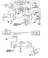
- Figure 1 illustrates generally at 10 a therapeutic apparatus in accordance with the present invention.
- the apparatus includes a casing 12, to which there is releasably connected a hand held active electrode or probe 14 adapted for point or spot application, and a pair of flat active electrodes 15, 16, each having the form of a rectangular plate which may be about four inches square.
- the electrode 15 is designated by the color red
- the electrode 16 is designated by the color black.
- a relatively large-flat indifferent electrode 18 which serves as a dispersive ground for the active electrodes.
- the casing 12 of the apparatus mounts a front control panel 19, and houses an electrical pulse generator for supplying a pulsed current to the selected electrode.
- the pulse generator is shown schematically at 20 in Figures 3-5, and is of conventional known design.
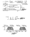
- the current typically has a waveform consisting of adjacent or twin pulses as shown in Figure 6, and is characterized by relatively high voltage, high peak but low average current, and very short pulse duration. The short duration of the pulses results in an inherently low power output, and no significant heat is generated in the electrodes.
- the control panel 19 includes an intensity control knob 22 which permits the therapist to selectively adjust the voltage to a level between about 1 to 500 volts, and in normal operation, the peak current ranges between about 50 to 400 milliamps.
- the duration of each pulse (measured at half peak height) is typically between about 15 to 30 microseconds when measured with a load impedance of 1000 ohms, it being understood that the pulse width will vary with the impedance of the patient's body. There is typically about 75 microseconds between the pulses of each pair, and the total duration of each pair of adjacent pulses is on the order of about 100 microseconds.
- the frequency of the twin pulses is controlled by the knob 24 in a range of between about 1 to 120 twin pulses per second, and a light 25 is positioned adjacent the knob 24 which is lighted with each pulse to visually indicate the pulse rate.
- the control panel 19 further mounts a master on-off power switch 26, a master timer 28 for permitting the total treatment time to be selected, and a meter 30 for visually displaying either the voltage or current (peak milliamps) as selected by the output switch 31. Moving the output switch 31 to one position causes the meter 30 to display the voltage and to light the voltage readout indicator 32, and moving the switch 31 to the other position causes the meter 30 to display the peak current and to light the current readout indicator 34. Further, there is provided a polarity selector 35 for selecting either a positive or negative polarity for the pair of electrodes, and a function selector switch 36 for selecting the mode of operation. Specifically, the selector switch 36 permits selection between the hand held probe 14 and the pair of electrodes 15, 16.
- the output When the selector 36 is in the "probe” position the output is operatively connected to the probe 14 and in continuous operation. In the “continuous”, “surge”, and “reciprocate” positions, the output is operatively connected to the pair of electrodes 15, l6. In “continuous” mode, the electrodes are on continuously, in “surge” mode, both electrodes are cycled on and off together at rates selected by the surge-on control dial 38 and surge-off control dial 40, and in the manner illustrated in Figure 7 (wherein each vertical line represents a twin pulse). A light 41 is provided on the control panel adjacent the surge-on dial 38 which is lighted when an output is being applied.
- the "reciprocate" mode involves three selectable time periods, namely 2.5, 5 and 10 seconds. These three positions determine the time that one electrode is on while the other is off, and at the selected interval, the electrode that is on will switch off and the electrode that is off will switch on. This alternate switching continues throughout the total treatment time as set by the master timer.
- a safety circuit (not shown) is provided which terminates the output.
- the output will remain at zero until the apparatus is reset, by rotation of the intensity control knob 22 to zero.
- the intensity will always commence at zero with the commencement of any treatment mode.
- the control panel 19 further mounts an intensity balance knob 42 which is operable in the "reciprocate" mode as hereinafter further described, and a pair of indicator lights 43, 44 respectively designated red and black for visually indicating which of the pair of electrodes 15, 16 is operatively connected to the circuit.
- FIG. 3 illustrates an intensity balance circuit adapted for use with the present invention when operated in the "reciprocate" mode.
- a reference voltage is applied in the line 45 which includes the intensity control 46 which is adjusted by the intensity knob 22.
- the voltage is then fed into the parallel branch lines 47, 48.
- a separate voltage controlled attenuator 50, 51 is positioned in each of the branch lines, together with an associated solid state switch 52, 53.
- the two branch lines then join and pass through the conventional pulse generator 20 which produces a high voltage pulsed current as described above.
- the output of the generator is directed to a pair of relays 55, 56 which are respectively connected to the electrodes 15 and 16.
- the intensity balance circuit further includes a bridge network 58, which is operatively connected to the intensity balance control knob 42 on the control panel, and the bridge network is operatively connected to each of the voltage controlled attenuators 50, 51.
- a reciprocate timing and switching logic circuit 60 controls the two solid state switches 52, 53, and incorporates the reciprocate timing portion of the switch 36 mounted on the control panel of the apparatus.
- the circuit 60 further controls the pair of relays 55, 56 for selectively activating the electrodes 15, 16, concurrently with the closing of the associated solid state switch 52, 53.
- the intensity balance control knob 42 is initially placed in the middle of its rotation, and the bridge is thus balanced such that there is no output from the bridge. If the knob 42 is turned clockwise, the wiper of the control moves upwardly as seen in Figure 3 and becomes more positive than the juncture 62 between the two resistors 63, 64 causing the attenuator 51 in the black line to increase its attenuation and thus decrease its voltage, while the attenuation in the red line is unchanged. If the knob 42 is turned counterclockwise, the wiper becomes more negative than the resistor junction 62, causing the red line attenuator 50 to increasingly attenuate the intensity level, while that in the black line is unchanged.
- the reciprocate timing logic 60 alternately interconnects the red electrode and the black electrode to the output circuit, concurrently with the closure of the associated switches 52, 53.
- the illustrated voltage attenuation circuit permits the therapist to selectively increase or decrease the current flowing to one electrode with respect to the current flowing to the other electrode. Further, the current may be changed without changing the impedance of the circuit, which would interfere with the measurement of the peak current to the body, and the circuit will maintain a low impedance as compared to the impedance of the patient's body, to thereby permit accurate measurement of the peak current to the body.
- Figure 4 illustrates a circuit for continuously monitoring and visually displaying the peak current value of the pulsed current flowing from the generator 20.
- the circuit includes a current transformer 70 having an associated shunt 71, which develops a voltage that is proportional to the current flowing to the electrode.
- the transformer also serves to isolate the circuit from the patient for safety purposes.
- a wide band amplifier 72 amplifies the output of the current transformer by for example a factor of forty, and then feeds the large output to the diode capacitor network 73.
- the diode acts to charge the capacitor to the peak voltage from the wide band amplifier.
- the buffer 75 provides an output that is the same as the voltage to which the capacitor is charged, and this output, which is proportional to the peak current, is displayed on the control panel meter 30 when the switch 31 is moved to the amperage readout position.
- the output is also fed back in line 76 to the wide band amplifier to compensate for nonlinearities in the diode and to control the gain of the wide band amplifier.
- the display meter 30 includes a pivotally mounted needle, and the needle movement follows the output of the buffer 75 for limiting the rapid movement thereof.
- a preferred embodiment of a surge control circuit is illustrated schematically in Figure 5, and is composed of a function generator 80 and a voltage controlled attenuator 81 which modulates a reference voltage which controls the high voltage pulse generator 20.
- the function generator 80 produces a control voltage output with four controlled functions, namely, the surge-on time as determined by the setting of the dial 38 on the control panel, the surge-off time as determined by the setting of the dial 40, the ramp- time and the ramp-down time, note Figure 7.
- the surge-on dial 38 and the surge-off dial 40 each have a control variable from 0.1 to 10 seconds.
- the ramp-up time is proportional to the surge-on time
- the ramp-down time is fixed at .03 seconds.
- the control voltage from the function generator 80 is fed to the voltage controlled attenuator 81, which modulates the voltage determined by the variable intensity control 82, which is controlled by the knob 22 on the control panel.
- the modulated voltage in turn controls the output voltage of the pulse generator 20 from zero to the preset maximum intensity.
- the ramp-up time is about one third of the surge-on time as set by the dial 38.
- the therapist may effectively cushion the sensory shock to the patient at the commencement of each surge, by extending the surge-on time to thereby lengthen the ramp-up time. Further, such tieing of the ramp-up time to the surge-on time permits effective control without the use of additional dials on the control panel.
Landscapes
- Health & Medical Sciences (AREA)
- Life Sciences & Earth Sciences (AREA)
- Biomedical Technology (AREA)
- Biophysics (AREA)
- Heart & Thoracic Surgery (AREA)
- Engineering & Computer Science (AREA)
- Pain & Pain Management (AREA)
- Nuclear Medicine, Radiotherapy & Molecular Imaging (AREA)
- Radiology & Medical Imaging (AREA)
- Animal Behavior & Ethology (AREA)
- General Health & Medical Sciences (AREA)
- Public Health (AREA)
- Veterinary Medicine (AREA)
- Electrotherapy Devices (AREA)
Applications Claiming Priority (2)
| Application Number | Priority Date | Filing Date | Title |
|---|---|---|---|
| US06/223,318 US4580570A (en) | 1981-01-08 | 1981-01-08 | Electrical therapeutic apparatus |
| US223318 | 1988-07-25 |
Publications (1)
| Publication Number | Publication Date |
|---|---|
| EP0057048A1 true EP0057048A1 (de) | 1982-08-04 |
Family
ID=22835997
Family Applications (1)
| Application Number | Title | Priority Date | Filing Date |
|---|---|---|---|
| EP82300033A Withdrawn EP0057048A1 (de) | 1981-01-08 | 1982-01-05 | Elektrotherapeutisches Gerät |
Country Status (4)
| Country | Link |
|---|---|
| US (1) | US4580570A (de) |
| EP (1) | EP0057048A1 (de) |
| AU (1) | AU7925682A (de) |
| CA (1) | CA1189148A (de) |
Cited By (21)
| Publication number | Priority date | Publication date | Assignee | Title |
|---|---|---|---|---|
| EP0129483A1 (de) * | 1983-06-15 | 1984-12-27 | Medtronic, Inc. | Einrichtung zur Feststellung des Ansprechens eines Organs auf elektrische Stimulation |
| WO1985002547A1 (fr) * | 1983-12-08 | 1985-06-20 | Gyueling Zoltan | Procede therapeutique non-envahissant et installation electrique pour realiser ledit procede |
| EP0203336A1 (de) * | 1985-04-16 | 1986-12-03 | VEB Starkstrom-Anlagenbau Leipzig-Halle | Reizstromgerät sowie Verfahren zur Behandlung des menschlichen und tierischen Körpers mit Reizströmen |
| EP0291577A1 (de) * | 1987-05-20 | 1988-11-23 | PHYSIOMED-Medizintechnik GmbH | Vorrichtung zur Therapie von Lymphstauungen u.dgl. |
| WO1994025103A1 (en) * | 1993-04-28 | 1994-11-10 | Norma Johnson | Electrical muscle toning |
| US6512955B1 (en) | 2000-08-07 | 2003-01-28 | Mcenany Thomas J. | Electrical apparatus for therapeutic treatment |
| US7330753B2 (en) | 2001-04-18 | 2008-02-12 | Metacure N.V. | Analysis of eating habits |
| US7437195B2 (en) | 2001-01-05 | 2008-10-14 | Metalure N.V. | Regulation of eating habits |
| US7502649B2 (en) | 2003-06-20 | 2009-03-10 | Metacure Ltd. | Gastrointestinal methods and apparatus for use in treating disorders |
| US8295932B2 (en) | 2005-12-05 | 2012-10-23 | Metacure Limited | Ingestible capsule for appetite regulation |
| US8301256B2 (en) | 2005-06-02 | 2012-10-30 | Metacure Limited | GI lead implantation |
| US8442841B2 (en) | 2005-10-20 | 2013-05-14 | Matacure N.V. | Patient selection method for assisting weight loss |
| US8463404B2 (en) | 2005-03-24 | 2013-06-11 | Metacure Limited | Electrode assemblies, tools, and methods for gastric wall implantation |
| US8612016B2 (en) | 2004-08-18 | 2013-12-17 | Metacure Limited | Monitoring, analysis, and regulation of eating habits |
| US8666495B2 (en) | 1999-03-05 | 2014-03-04 | Metacure Limited | Gastrointestinal methods and apparatus for use in treating disorders and controlling blood sugar |
| US8792985B2 (en) | 2003-07-21 | 2014-07-29 | Metacure Limited | Gastrointestinal methods and apparatus for use in treating disorders and controlling blood sugar |
| US8934975B2 (en) | 2010-02-01 | 2015-01-13 | Metacure Limited | Gastrointestinal electrical therapy |
| US9101765B2 (en) | 1999-03-05 | 2015-08-11 | Metacure Limited | Non-immediate effects of therapy |
| US9174061B2 (en) | 2003-11-13 | 2015-11-03 | Zoll Medical Corporation | Multi-path transthoracic defibrillation and cardioversion |
| US9821158B2 (en) | 2005-02-17 | 2017-11-21 | Metacure Limited | Non-immediate effects of therapy |
| GB2553089A (en) * | 2016-08-15 | 2018-02-28 | Ipulse Medical Ltd | Device for providing pain relief |
Families Citing this family (51)
| Publication number | Priority date | Publication date | Assignee | Title |
|---|---|---|---|---|
| EP0196393B1 (de) * | 1985-04-01 | 1989-06-14 | Oscobal Ag | Elektrostimulationsgerät, insbesondere zur Skoliosebehandlung |
| FR2582947B1 (fr) * | 1985-06-07 | 1988-05-13 | Cgr Mev | Dispositif de traitement par hyperthermie |
| CN86103803B (zh) * | 1986-06-05 | 1987-11-18 | 北京信息工程学院 | 静电场治疗装置 |
| US4769881A (en) * | 1986-09-02 | 1988-09-13 | Pedigo Irby R | High precision tens apparatus and method of use |
| US4759368A (en) * | 1986-12-02 | 1988-07-26 | Medical Designs, Inc. | Transcutaneous nerve stimulator |
| USD302302S (en) | 1987-01-05 | 1989-07-18 | Amrex-Zetron, Inc. | Electronic nerve stimulator unit |
| USD302303S (en) | 1987-01-05 | 1989-07-18 | Amrex-Zetron, Inc. | Electronic nerve stimulator unit |
| US5074305A (en) * | 1987-07-14 | 1991-12-24 | Venomex, Incorporated | Method for treatment of toxins received from snake bites and the like |
| US4841973A (en) * | 1987-09-21 | 1989-06-27 | Stecker Harold D | Electrical stimulators |
| US4895154A (en) * | 1988-02-19 | 1990-01-23 | Staodynamics, Inc. | Electronic stimulating device for enhanced healing of soft tissue wounds |
| US4938223A (en) * | 1988-03-28 | 1990-07-03 | T. H. Charters, Inc. | Transcutaneous nerve block device |
| JPH0614759Y2 (ja) * | 1988-08-11 | 1994-04-20 | 伊藤超短波株式会社 | 低周波治療器 |
| US5109848A (en) * | 1989-05-22 | 1992-05-05 | Physiodynamics, Inc. | Electrotherapeutic apparatus |
| US5107835A (en) * | 1989-05-22 | 1992-04-28 | Physiodynamics | Electrotherapeutic treatment |
| US5063929A (en) * | 1989-08-25 | 1991-11-12 | Staodyn, Inc. | Electronic stimulating device having timed treatment of varying intensity and method therefor |
| US5193537A (en) * | 1990-06-12 | 1993-03-16 | Zmd Corporation | Method and apparatus for transcutaneous electrical cardiac pacing |
| US5205284A (en) * | 1990-06-12 | 1993-04-27 | Zoll Medical Corporation | Method and apparatus for transcutaneous electrical cardiac pacing with background stimulation |
| US5281219A (en) * | 1990-11-23 | 1994-01-25 | Medtronic, Inc. | Multiple stimulation electrodes |
| EP0594620A4 (de) * | 1991-07-15 | 1994-11-02 | Zmd Corp | Verfahren und gerät zur transkutanen herzreizung. |
| US5578060A (en) * | 1995-06-23 | 1996-11-26 | Chattanooga Group, Inc. | Physical therapy apparatus having an interactive interface, and method of configuring same |
| US5947901A (en) * | 1997-09-09 | 1999-09-07 | Redano; Richard T. | Method for hemodynamic stimulation and monitoring |
| US5974342A (en) * | 1997-10-16 | 1999-10-26 | Electrologic Of America, Inc. | Electrical stimulation therapy method and apparatus |
| IT245957Y1 (it) * | 1998-01-29 | 2002-03-26 | H T M Srl | Elettro-stimolatore muscolare conformato in modo da evitaresensazioni di dolore ed arrossamenti della cute |
| USD414266S (en) | 1998-08-11 | 1999-09-21 | CPR Promt, L.L.C. | Defibrillator |
| USD435904S1 (en) | 1999-04-30 | 2001-01-02 | Medi-Pulse (Proprietary) Limited | Medical treatment unit |
| US7013179B2 (en) * | 2000-01-07 | 2006-03-14 | Biowave Corporation | Percutaneous electrode array |
| EP1246665B1 (de) | 2000-01-07 | 2005-08-24 | Biowave Corporation | Vorrichtung zur elektrotherapie |
| US20080033492A1 (en) * | 2000-01-07 | 2008-02-07 | Biowave Corporation | Electro-therapy method |
| US20050187591A1 (en) * | 2000-01-07 | 2005-08-25 | Biowave Corporation | Electro therapy method and apparatus |
| US6505079B1 (en) * | 2000-09-13 | 2003-01-07 | Foster Bio Technology Corp. | Electrical stimulation of tissue for therapeutic and diagnostic purposes |
| US6882884B1 (en) | 2000-10-13 | 2005-04-19 | Soundskin, L.L.C. | Process for the stimulation of production of extracellular dermal proteins in human tissue |
| US6535767B1 (en) * | 2001-08-21 | 2003-03-18 | James W. Kronberg | Apparatus and method for bioelectric stimulation, healing acceleration and pain relief |
| CA2926344C (en) | 2001-10-17 | 2018-06-19 | Compex Technologies, Inc. | Electrical nerve stimulation stimulator |
| CA2485271A1 (en) * | 2002-05-09 | 2003-11-20 | Daemen College | Electrical stimulation unit and waterbath system |
| US20040015212A1 (en) * | 2002-05-31 | 2004-01-22 | Empi, Corp. | Electrotherapy stimulation device having electrode peel off detection capabilities |
| US20040210270A1 (en) * | 2002-07-26 | 2004-10-21 | John Erickson | High frequency pulse generator for an implantable neurostimulator |
| US6856837B2 (en) * | 2002-11-20 | 2005-02-15 | O'kelly Gregory C. | Method and device for electrochemically building of muscle |
| CA2530396C (en) | 2003-06-24 | 2015-03-24 | Healthonics, Inc. | Apparatus and method for bioelectric stimulation, healing acceleration, pain relief, or pathegen devitalization |
| US7613517B2 (en) * | 2004-10-20 | 2009-11-03 | Teodor Goroszeniuk | Method for neurostimulation |
| EP1861005A1 (de) * | 2005-03-18 | 2007-12-05 | Trustees Of The Stevens Institute Of Technology | Gerät zur diagnose von muskelschmerz und dessen anwendung |
| US7319902B2 (en) * | 2005-05-09 | 2008-01-15 | O'kelly Gregory | Method and device for electrochemical rejuvenation of skin and underlying tissue, and muscle building |
| JP2009523036A (ja) * | 2005-12-05 | 2009-06-18 | ブローガン,マイケル・エス | 電気刺激ユニットおよび水浴 |
| WO2010068797A1 (en) * | 2008-12-10 | 2010-06-17 | Waverx, Inc. | Devices, systems and methods for preventing and treating sensation loss |
| US8267851B1 (en) | 2009-06-16 | 2012-09-18 | James M Kroll | Method and apparatus for electrically generating signal for inducing lucid dreaming |
| US9526892B2 (en) | 2009-10-05 | 2016-12-27 | ARP Wave LLC | Electro-therapeutic stimulation |
| US9302102B2 (en) * | 2009-10-05 | 2016-04-05 | Arp Manufacturing Llc | Electro-therapeutic stimulator |
| US8583240B2 (en) | 2011-07-18 | 2013-11-12 | Marcy L. Freed | Device and method for treating dysphagia with electrical stimulation |
| USD903132S1 (en) * | 2017-10-30 | 2020-11-24 | Novoxel Ltd. | Device for skin treatment |
| USD903133S1 (en) * | 2017-12-13 | 2020-11-24 | Novoxel Ltd. | Device for skin treatment |
| USD950081S1 (en) * | 2019-04-26 | 2022-04-26 | Lam Skin Care Products Limited | Device casing with color coded power setting buttons and two probe holding connectors |
| JP7697644B2 (ja) | 2019-05-31 | 2025-06-24 | オージー技研株式会社 | 電気刺激装置 |
Citations (10)
| Publication number | Priority date | Publication date | Assignee | Title |
|---|---|---|---|---|
| GB877029A (en) * | 1958-09-12 | 1961-09-13 | Relaxacizor Inc | Electronic muscle stimulator |
| GB1129142A (en) * | 1965-05-26 | 1968-10-02 | Medical And Biolog Instrumenta | A circuit arrangement for an electric muscle stimulator |
| DE1943830A1 (de) * | 1968-08-31 | 1970-03-05 | Akademia Medyczana W Warszawie | Verfahren zur Synchronisation und Stimulation von implantierten Herzstimulatoren mit Dauerrhythmus mittels Impulspaaren sowie Schaltung zur Durchfuehrung dieses Verfahrens |
| US3851651A (en) * | 1972-12-22 | 1974-12-03 | P Icenbice | Facial stimulating apparatus having sequentially energized electrodes |
| US3881494A (en) * | 1973-05-22 | 1975-05-06 | Jr James M Paul | Electro pulse arthritic physiotherapy system |
| FR2340743A1 (fr) * | 1976-02-13 | 1977-09-09 | Traitement Information Tech Nl | Appareil d'electrosommeil |
| US4084595A (en) * | 1976-07-15 | 1978-04-18 | Med General, Inc. | Transcutaneous nerve stimulator |
| EP0000477A1 (de) * | 1977-06-27 | 1979-02-07 | Bernard Jankelson | Unterkieferstimulator |
| US4177819A (en) * | 1978-03-30 | 1979-12-11 | Kofsky Harvey I | Muscle stimulating apparatus |
| DE3006797A1 (de) * | 1979-02-23 | 1980-09-04 | Bello Lino Lo | Reizstromgeraet |
Family Cites Families (26)
| Publication number | Priority date | Publication date | Assignee | Title |
|---|---|---|---|---|
| US1999729A (en) * | 1933-12-16 | 1935-04-30 | Westinghouse X Ray Co Inc | Apparatus for producing graduated involuntary muscular contractions |
| US2295585A (en) * | 1939-09-16 | 1942-09-15 | Robert J Lindquist | Therapeutic current and means for producing the same |
| DE919961C (de) * | 1951-08-28 | 1954-11-08 | Siemens Reiniger Werke Ag | Elektromedizinischer Reizstromtherapieapparat |
| US2764683A (en) * | 1952-04-18 | 1956-09-25 | Physical Medicine Products Co | Low voltage electro-therapy generator |
| US2713120A (en) * | 1952-10-22 | 1955-07-12 | Mostofsky David | Electronic stimulator |
| FR1118061A (fr) * | 1954-06-14 | 1956-05-31 | Electromedica | Pupitre de commande pour applications électrothérapiques, notamment pour stimulothérapie |
| US2808826A (en) * | 1956-01-19 | 1957-10-08 | Teca Corp | Electro-diagnostic apparatus and a circuit therefor |
| US3055372A (en) * | 1960-02-11 | 1962-09-25 | Relaxacizor Inc | Device for electrical treatment of bodily tissues |
| US3127895A (en) * | 1962-07-02 | 1964-04-07 | Dynapower System Corp | Therapeutic pulse generation and control circuit |
| US3565080A (en) * | 1964-12-21 | 1971-02-23 | Burroughs Wellcome Co | Neuromuscular block monitoring apparatus |
| US3329148A (en) * | 1965-09-21 | 1967-07-04 | Dynapower Systems Corp Of Cali | Control of electrotherapeutic apparatus |
| GB1286075A (en) * | 1968-09-20 | 1972-08-16 | Dietmar Rudolf Garbe | Incontinence control |
| US3648708A (en) * | 1969-06-23 | 1972-03-14 | Mehdi Haeri | Electrical therapeutic device |
| US3791373A (en) * | 1972-03-02 | 1974-02-12 | Univ Southern Illinois | Portable electroanesthesia device with automatic power control |
| JPS6025138B2 (ja) * | 1973-12-28 | 1985-06-17 | 宏 佐藤 | 可聴周波帯域交流電気治療器 |
| US4237887A (en) * | 1975-01-23 | 1980-12-09 | Valleylab, Inc. | Electrosurgical device |
| US4014347A (en) * | 1975-05-27 | 1977-03-29 | Staodynamics, Inc. | Transcutaneous nerve stimulator device and method |
| US4121592A (en) * | 1975-08-04 | 1978-10-24 | Critical Systems, Inc. | Apparatus for heating tissue |
| US4069827A (en) * | 1975-08-20 | 1978-01-24 | The Burdick Corporation | Diathermy apparatus |
| US4068669A (en) * | 1975-11-24 | 1978-01-17 | Stimulation Technology, Inc. | Stimulator fault protection circuit |
| US4095602A (en) * | 1976-09-27 | 1978-06-20 | Leveen Harry H | Multi-portal radiofrequency generator |
| US4197851A (en) * | 1977-04-14 | 1980-04-15 | Fellus Victor M | Apparatus for emitting high-frequency electromagnetic waves |
| US4140130A (en) * | 1977-05-31 | 1979-02-20 | Storm Iii Frederick K | Electrode structure for radio frequency localized heating of tumor bearing tissue |
| SU692606A1 (ru) * | 1977-07-29 | 1979-10-25 | Научно-Исследовательский Институт Акушерства И Гинекологии | Устройство дл дистанционной электроанальгезии-лэнар |
| DE2749792A1 (de) * | 1977-11-07 | 1979-05-10 | Siemens Ag | Elektromedizinisches geraet |
| US4188927A (en) * | 1978-01-12 | 1980-02-19 | Valleylab, Inc. | Multiple source electrosurgical generator |
-
1981
- 1981-01-08 US US06/223,318 patent/US4580570A/en not_active Expired - Fee Related
-
1982
- 1982-01-04 CA CA000393495A patent/CA1189148A/en not_active Expired
- 1982-01-05 EP EP82300033A patent/EP0057048A1/de not_active Withdrawn
- 1982-01-07 AU AU79256/82A patent/AU7925682A/en not_active Abandoned
Patent Citations (10)
| Publication number | Priority date | Publication date | Assignee | Title |
|---|---|---|---|---|
| GB877029A (en) * | 1958-09-12 | 1961-09-13 | Relaxacizor Inc | Electronic muscle stimulator |
| GB1129142A (en) * | 1965-05-26 | 1968-10-02 | Medical And Biolog Instrumenta | A circuit arrangement for an electric muscle stimulator |
| DE1943830A1 (de) * | 1968-08-31 | 1970-03-05 | Akademia Medyczana W Warszawie | Verfahren zur Synchronisation und Stimulation von implantierten Herzstimulatoren mit Dauerrhythmus mittels Impulspaaren sowie Schaltung zur Durchfuehrung dieses Verfahrens |
| US3851651A (en) * | 1972-12-22 | 1974-12-03 | P Icenbice | Facial stimulating apparatus having sequentially energized electrodes |
| US3881494A (en) * | 1973-05-22 | 1975-05-06 | Jr James M Paul | Electro pulse arthritic physiotherapy system |
| FR2340743A1 (fr) * | 1976-02-13 | 1977-09-09 | Traitement Information Tech Nl | Appareil d'electrosommeil |
| US4084595A (en) * | 1976-07-15 | 1978-04-18 | Med General, Inc. | Transcutaneous nerve stimulator |
| EP0000477A1 (de) * | 1977-06-27 | 1979-02-07 | Bernard Jankelson | Unterkieferstimulator |
| US4177819A (en) * | 1978-03-30 | 1979-12-11 | Kofsky Harvey I | Muscle stimulating apparatus |
| DE3006797A1 (de) * | 1979-02-23 | 1980-09-04 | Bello Lino Lo | Reizstromgeraet |
Cited By (25)
| Publication number | Priority date | Publication date | Assignee | Title |
|---|---|---|---|---|
| EP0129483A1 (de) * | 1983-06-15 | 1984-12-27 | Medtronic, Inc. | Einrichtung zur Feststellung des Ansprechens eines Organs auf elektrische Stimulation |
| WO1985002547A1 (fr) * | 1983-12-08 | 1985-06-20 | Gyueling Zoltan | Procede therapeutique non-envahissant et installation electrique pour realiser ledit procede |
| EP0203336A1 (de) * | 1985-04-16 | 1986-12-03 | VEB Starkstrom-Anlagenbau Leipzig-Halle | Reizstromgerät sowie Verfahren zur Behandlung des menschlichen und tierischen Körpers mit Reizströmen |
| EP0291577A1 (de) * | 1987-05-20 | 1988-11-23 | PHYSIOMED-Medizintechnik GmbH | Vorrichtung zur Therapie von Lymphstauungen u.dgl. |
| WO1994025103A1 (en) * | 1993-04-28 | 1994-11-10 | Norma Johnson | Electrical muscle toning |
| US8666495B2 (en) | 1999-03-05 | 2014-03-04 | Metacure Limited | Gastrointestinal methods and apparatus for use in treating disorders and controlling blood sugar |
| US9101765B2 (en) | 1999-03-05 | 2015-08-11 | Metacure Limited | Non-immediate effects of therapy |
| US6512955B1 (en) | 2000-08-07 | 2003-01-28 | Mcenany Thomas J. | Electrical apparatus for therapeutic treatment |
| US7437195B2 (en) | 2001-01-05 | 2008-10-14 | Metalure N.V. | Regulation of eating habits |
| US7330753B2 (en) | 2001-04-18 | 2008-02-12 | Metacure N.V. | Analysis of eating habits |
| US7502649B2 (en) | 2003-06-20 | 2009-03-10 | Metacure Ltd. | Gastrointestinal methods and apparatus for use in treating disorders |
| US8792985B2 (en) | 2003-07-21 | 2014-07-29 | Metacure Limited | Gastrointestinal methods and apparatus for use in treating disorders and controlling blood sugar |
| US9174061B2 (en) | 2003-11-13 | 2015-11-03 | Zoll Medical Corporation | Multi-path transthoracic defibrillation and cardioversion |
| US10022550B2 (en) | 2003-11-13 | 2018-07-17 | Zoll Medical Corporation | Multi-path transthoracic defibrillation and cardioversion |
| US11097118B2 (en) | 2003-11-13 | 2021-08-24 | Zoll Medical Corporation | Multi-path transthoracic defibrillation and cardioversion |
| US8612016B2 (en) | 2004-08-18 | 2013-12-17 | Metacure Limited | Monitoring, analysis, and regulation of eating habits |
| US9821158B2 (en) | 2005-02-17 | 2017-11-21 | Metacure Limited | Non-immediate effects of therapy |
| US8463404B2 (en) | 2005-03-24 | 2013-06-11 | Metacure Limited | Electrode assemblies, tools, and methods for gastric wall implantation |
| US8301256B2 (en) | 2005-06-02 | 2012-10-30 | Metacure Limited | GI lead implantation |
| US8442841B2 (en) | 2005-10-20 | 2013-05-14 | Matacure N.V. | Patient selection method for assisting weight loss |
| US8295932B2 (en) | 2005-12-05 | 2012-10-23 | Metacure Limited | Ingestible capsule for appetite regulation |
| US8934975B2 (en) | 2010-02-01 | 2015-01-13 | Metacure Limited | Gastrointestinal electrical therapy |
| GB2553089A (en) * | 2016-08-15 | 2018-02-28 | Ipulse Medical Ltd | Device for providing pain relief |
| GB2553089B (en) * | 2016-08-15 | 2018-11-21 | Ipulse Medical Ltd | Device for providing pain relief |
| US11752336B2 (en) | 2016-08-15 | 2023-09-12 | Ipulse Medical Ltd. | Electrical device for providing pain relief |
Also Published As
| Publication number | Publication date |
|---|---|
| AU7925682A (en) | 1982-07-15 |
| US4580570A (en) | 1986-04-08 |
| CA1189148A (en) | 1985-06-18 |
Similar Documents
| Publication | Publication Date | Title |
|---|---|---|
| US4580570A (en) | Electrical therapeutic apparatus | |
| US4340063A (en) | Stimulation device | |
| US5063929A (en) | Electronic stimulating device having timed treatment of varying intensity and method therefor | |
| US4759368A (en) | Transcutaneous nerve stimulator | |
| US4177819A (en) | Muscle stimulating apparatus | |
| US4431002A (en) | Modulated deep afferent stimulator | |
| US5324317A (en) | Interferential stimulator for applying low frequency alternating current to the body | |
| US4456012A (en) | Iontophoretic and electrical tissue stimulation device | |
| CA1335302C (en) | Microprocessor controlled electronic stimulating device having biphasic pulse output | |
| EP0111229B1 (de) | Gerät zur elektrischen Stimulation der Nerven | |
| US8108047B2 (en) | Device and method for the treatment of pain with electrical energy | |
| US4392496A (en) | Neuromuscular stimulator | |
| US6210403B1 (en) | Automatic control for energy from an electrosurgical generator | |
| USRE32091E (en) | Neuromuscular stimulator | |
| US5964789A (en) | Transcutaneous electric muscle/nerve controller/feedback unit | |
| USRE35987E (en) | Output pulse compensation for therapeutic-type electronic devices | |
| US3866600A (en) | Iagnostic and therapeutic apparatus for cosmetically and hygienically treating skin | |
| US4249537A (en) | Current controlled muscle stimulator | |
| KR950014481B1 (ko) | 전기자극 장치 | |
| US20020068961A1 (en) | Electrical stimulator and method of use | |
| GB2123698A (en) | Biological electrical stimulators | |
| CA2132944C (en) | Nerve stimulation apparatus and method | |
| US4815475A (en) | Modulation system for evoked response stimulation and method | |
| US4442839A (en) | Method of modulating energy in train of electrical pulses | |
| RU2722812C1 (ru) | Способ нейроподобной динамической электростимуляции и устройство для его осуществления |
Legal Events
| Date | Code | Title | Description |
|---|---|---|---|
| PUAI | Public reference made under article 153(3) epc to a published international application that has entered the european phase |
Free format text: ORIGINAL CODE: 0009012 |
|
| AK | Designated contracting states |
Designated state(s): AT BE CH DE FR GB IT LU NL SE |
|
| 17P | Request for examination filed |
Effective date: 19830131 |
|
| STAA | Information on the status of an ep patent application or granted ep patent |
Free format text: STATUS: THE APPLICATION IS DEEMED TO BE WITHDRAWN |
|
| 18D | Application deemed to be withdrawn |
Effective date: 19850716 |
|
| RIN1 | Information on inventor provided before grant (corrected) |
Inventor name: SARREL, IVAN DONALD Inventor name: BLEY, DAVID BRUCE |