EP0057112A2 - Die Laufzeit selbstkorrigierendes, elektrisches Filter - Google Patents
Die Laufzeit selbstkorrigierendes, elektrisches Filter Download PDFInfo
- Publication number
- EP0057112A2 EP0057112A2 EP82400007A EP82400007A EP0057112A2 EP 0057112 A2 EP0057112 A2 EP 0057112A2 EP 82400007 A EP82400007 A EP 82400007A EP 82400007 A EP82400007 A EP 82400007A EP 0057112 A2 EP0057112 A2 EP 0057112A2
- Authority
- EP
- European Patent Office
- Prior art keywords
- filter
- self
- resonator
- input
- correction
- Prior art date
- Legal status (The legal status is an assumption and is not a legal conclusion. Google has not performed a legal analysis and makes no representation as to the accuracy of the status listed.)
- Granted
Links
- 230000008878 coupling Effects 0.000 claims abstract description 28
- 238000010168 coupling process Methods 0.000 claims abstract description 28
- 238000005859 coupling reaction Methods 0.000 claims abstract description 28
- 238000012937 correction Methods 0.000 claims abstract description 20
- 238000001914 filtration Methods 0.000 claims abstract description 8
- 239000003990 capacitor Substances 0.000 claims description 15
- 230000006978 adaptation Effects 0.000 claims description 5
- 238000010586 diagram Methods 0.000 description 7
- 238000000034 method Methods 0.000 description 7
- 238000005457 optimization Methods 0.000 description 5
- 238000012360 testing method Methods 0.000 description 3
- 230000015572 biosynthetic process Effects 0.000 description 2
- 239000011159 matrix material Substances 0.000 description 2
- 238000001308 synthesis method Methods 0.000 description 2
- 238000003786 synthesis reaction Methods 0.000 description 2
- 230000005540 biological transmission Effects 0.000 description 1
- 238000013461 design Methods 0.000 description 1
- 230000007274 generation of a signal involved in cell-cell signaling Effects 0.000 description 1
- 238000012216 screening Methods 0.000 description 1
- 230000008054 signal transmission Effects 0.000 description 1
- 238000012546 transfer Methods 0.000 description 1
Images


Classifications
-
- H—ELECTRICITY
- H03—ELECTRONIC CIRCUITRY
- H03H—IMPEDANCE NETWORKS, e.g. RESONANT CIRCUITS; RESONATORS
- H03H7/00—Multiple-port networks comprising only passive electrical elements as network components
- H03H7/01—Frequency selective two-port networks
- H03H7/17—Structural details of sub-circuits of frequency selective networks
- H03H7/1741—Comprising typical LC combinations, irrespective of presence and location of additional resistors
- H03H7/1775—Parallel LC in shunt or branch path
-
- H—ELECTRICITY
- H03—ELECTRONIC CIRCUITRY
- H03H—IMPEDANCE NETWORKS, e.g. RESONANT CIRCUITS; RESONATORS
- H03H7/00—Multiple-port networks comprising only passive electrical elements as network components
- H03H7/01—Frequency selective two-port networks
- H03H7/075—Ladder networks, e.g. electric wave filters
-
- H—ELECTRICITY
- H03—ELECTRONIC CIRCUITRY
- H03H—IMPEDANCE NETWORKS, e.g. RESONANT CIRCUITS; RESONATORS
- H03H7/00—Multiple-port networks comprising only passive electrical elements as network components
- H03H7/01—Frequency selective two-port networks
- H03H7/17—Structural details of sub-circuits of frequency selective networks
- H03H7/1708—Comprising bridging elements, i.e. elements in a series path without own reference to ground and spanning branching nodes of another series path
Definitions
- the present invention relates to self-corrected electric filters, and more particularly to self-corrected electric filters with elements with localized constants, of the pa% band type, making it possible to filter analog or digital signals in a wide frequency band and making it possible to correct the distortion of group propagation time in this frequency band.
- Such filters are particularly useful in radio-relay systems.
- conventional electrical filters are used.
- Conventional filters do not correct the distortion of group delay.
- the passage time at the different frequencies of the passband is not constant.
- the group propagation time increases from a low value for the central frequencies of the passband to a high value for the limit frequencies of the passband.
- the group delay correction function is performed by correction networks. These networks are very often made up of one or more cells comprising active elements. When there are several cells in the correction network, each cell is isolated from the adjacent cells by a transistor. These corrective networks are cascaded following the filter. For a radio-relay system, it is common to use two cascaded cells for phase correction. The center frequencies of the two cells are located on either side of the center frequency of the bandpass filter that one seeks to compensate for.
- microwave filters with narrow bandwidth are used.
- the group delay correction function is performed using multiple coupled cavities.
- JD RHODES Generalized linear phase filter by coupling cavity direct
- the invention proposes a self-corrected electric filter with elements with localized constants, comprising first input adaptation means for receiving the wide input signal, adapting it and transmitting it to filtering means. incorporated. by a set of filter cells in even number and in cascade to filter the broadband signal and transmit it to second output adaptation means, characterized in that it also includes correction means constituted by secondary couplings placed between at least two filter cells in order to carry out a self-correction of the group propagation time.
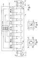
- the self-correcting electric filter according to the invention receives the input signal by a first pair of access terminals El, E2. This first pair of access terminals constitutes the input of the filter.
- An input impedance adapter 2.1 receives this signal in order to adapt it and transmit it to the screening means.
- the 2.1 input impedance adapter has 2 inputs and 2 outputs. The two outputs are connected to the inputs of the filtering means 3.
- These means comprise two inputs, two outputs, and are constituted by a number n of resonators; n being an integer, even and greater than 2. On the schematic diagram we are limited to n.equal to 8.
- Each resonator has a first and a second input, a first and a second output.
- the outputs of a first resonator are connected directly or indirectly to the inputs of a second resonator. This connection is called a cascade connection.
- the 2 outputs of the filtering means 3 are connected to an output impedance adapter 2.2.
- the two outputs of the filtering means 3 are the two outputs of the last resonator.
- the two outputs of the output impedance adapter 2.2 are connected to the second filter access terminals SI and S2. These two terminals constitute the outputs of the filter.
- the group propagation delay self-correction means 4 are connected to the filtering means 3 by means of adjacent couplings 4.5.
- the adjacent couplings consist of elements with localized constants Mi, j.
- Each resonator has an output connected to an input of the adjacent resonator by means of an adjacent coupling Mi, j.
- Figures 4 and 5 show the electrical diagram of the resonators.
- FIG. 4 represents a first mode of connection of a non-adjacent coupling on a first output of a resonator.
- FIG. 5 represents a second method of connection.
- the two resonators shown in FIGS. 4 and 5 are identical in their constitution. They conventionally include a capacitor in parallel on an inductor (and possibly a resistor in parallel on the inductor or on the capacitor to damp the resonator) having values determined to resonate at the tuning frequency.
- the resonators have two inputs and two outputs.
- the resonator has a first input and a first output which are subjected to the same first potential.
- the second input and the second output are subject to the same second potential.
- the adjacent coupling corresponding to this resonator is connected to the first output.
- Figure 5 differs from Figure 4 in one point.
- the first output is in this case taken at a midpoint N of the inductance.
- the non-adjacent coupling is connected at this point N.
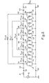
- FIG. 2 represents a particular embodiment of the filter according to the invention.
- the filter is produced for a central frequency which lies in the intermediate frequency range around 70 MHz.
- the 3 dB bandwidth is 17.5 MHz.
- the filter therefore has a large bandwidth according to the usual criteria.
- the filter is supplied by a receiver mixer represented in the diagram by a generator G, supplying a signal of frequency 70 MHz , and of amplitude Vo.
- the internal impedance R of the generator G is 75.
- the signal delivered by the generator is applied to the input of the filter between the access terminals El and E2.
- the second input E2 of the filter is at potential O.
- the impedance adapters 2.1 and 2.2 are capacitors CE and CS.
- the capacitor CE is connected between the input E and the first input of the first resonator R1.
- the capacitor CS is in series between the output SI and the last resonator R8.
- the two capacitors are equal to 24.96 pF in this particular example, taking into account the signal generation means.
- the filtering means 3 consist of 8 resonators R1, R2 ... R8. Each resonator is identical to that shown in FIG. 4.
- the first input 1E, and the first output 1S of the resonators are at the same potential. This same potential constitutes for each resonator, a node N1, N2 .... N8.
- the second inputs and second outputs are at potential O.
- Each resonator is connected to the next, via the adjacent couplings, which are self-inductive except between the two central resonators where the coupling is capacitive.
- the non-adjacent coupling Ml, 8 between the 1 st and the 8 th resonator is self-inductive.
- the non-adjacent couplings M2.7 and M3.6 respectively between the 2 nd and the 7 th resonator, and the 3 rd and 6 th resonator are capacitive.
- each inductance can be replaced by an equivalent element either an inductance well determined in series with a capacitor also well determined either an inductance in parallel on a capacitor or three inductors connected in the form of "T", it is that is to say a first inductance in series with a second and a third connected between the common point of the two first and a given potential.
- the values of the adjacent or non-adjacent couplings are determined from the filter synthesis method.
- This synthesis method consists in finding the coupling matrix and the adaptation coefficients to obtain a requested filter transfer function. It is known for narrow bandwidths. The results obtained are therefore not optimized.
- the calculations of the self-inductive and capacitive elements are carried out from the following equations:
- the self-inductive and capacitive elements of the resonators are calculated using the following equations: fo is the central frequency of the filter, fp the upper frequency of the last pulse.
- R is the internal resistance of the generator
- Rn is the resistance of the load
- Mi, j is the order term i, j of the coupling matrix M.
- An inductance Lo is equivalent to an inductance L in series with a resistance R equal to L 2 fo / Ql where Ql is the overvoltage coefficient of the inductance L, R represents the losses.
- a capacitor Co is equivalent to a capacitor C in parallel on a resistance R equal to Qc / C2 fo where Qc is the overvoltage coefficient of capacitor C.
- the optimization method is an iterative method; at each iteration, a nonlinear problem to be solved is replaced by a linear approximation. When the requested precision is reached, the iteration is stopped.
- the results are further optimized by adjusting the couplings obtained as a function of the frequency. An amplitude curve is obtained having a minimum of ripple. This curve also has arithmetric symmetry with respect to the central frequency Fo. An arithmetric symmetry of the group propagation time curve is thus also obtained.
- the amplitude curve A of the filter is shown in FIG. 3.
- the values of the frequencies in MHz are plotted on the abscissa.
- the amplitude attenuation (or gain) in decibels is plotted on the ordinate.
- the arithmetic symmetry of the filter is translated by a symmetry of the curve with respect to the central frequency. There is arithmetric symmetry up to 25 dB of out-of-band rejection. This means that it still has symmetry beyond the cutoff frequencies for an attenuation of 25 dB.
- This attenuation curve has steep slopes having substantially the same pace at the two cutoff frequencies. This is due to the arithmetric symmetry characteristics of the filter.
- the group T propagation time curve is also shown in FIG. 3. On the abscissa are the frequencies in MHz. The coordinates are shown in nano seconds. It can be seen that the group propagation time curve has the same characteristic as the attenuation curve, namely, arithmetric symmetry. It is further noted that there is practically no variation in the propagation time between 63 MHz and 77 MHz. The difference between 77 MHz and 63 MHz represents roughly 80 percent of the useful band of the filter. There is therefore a very good correction for group delay variation in the 80 percent of the useful band.
- Two other embodiments were made under the same supply and load conditions as in the first embodiment with bandwidths even wider than 17.5 MHz.
- One of these two embodiments is a filter whose central frequency is around 70 MHz and whose bandwidth is substantially equal to 20 MHz.
- the amplitude and T1 curves of group propagation time are shown in FIG. 6.
- the other embodiment is a filter whose central frequency is around 70 MHz and whose passband is substantially equal to 36 MHz, or about 50% of the value of the center frequency.
- the A2 amplitude and T2 curves of group propagation times are shown in figure 6. These two filters are shown diagrammatically in figure 2.
- the results of the couplings obtained for the filter whose passband is substantially equal to 36 MHz are the following:
- the results obtained for these two other embodiments corresponding to wider bandwidths make it possible to obtain a attenuation curve A1, A2 having an arithmetic symmetry up to 25 dB of out-of-band rejection, and a group propagation time curve T1, T2 also having arithmetic symmetry and a very good correction of group propagation time in the 80 percent of the useful band.
- the three embodiments described underwent a temperature variation test. The tests were carried out between a minimum temperature substantially equal to -30 ° C, and a maximum temperature substantially equal to + 70 ° C. After these tests, the amplitude and group propagation time curves undergo negligible variations, and remain very close to the ideal filter response.
Landscapes
- Control Of Motors That Do Not Use Commutators (AREA)
- Filters And Equalizers (AREA)
- Networks Using Active Elements (AREA)
- Cell Separators (AREA)
- Filters That Use Time-Delay Elements (AREA)
Priority Applications (1)
| Application Number | Priority Date | Filing Date | Title |
|---|---|---|---|
| AT82400007T ATE17067T1 (de) | 1981-01-23 | 1982-01-05 | Die laufzeit selbstkorrigierendes, elektrisches filter. |
Applications Claiming Priority (2)
| Application Number | Priority Date | Filing Date | Title |
|---|---|---|---|
| FR8101294A FR2498846B1 (fr) | 1981-01-23 | 1981-01-23 | Filtres electriques autocorriges en temps de propagation de groupe |
| FR8101294 | 1981-01-23 |
Publications (3)
| Publication Number | Publication Date |
|---|---|
| EP0057112A2 true EP0057112A2 (de) | 1982-08-04 |
| EP0057112A3 EP0057112A3 (en) | 1982-08-11 |
| EP0057112B1 EP0057112B1 (de) | 1985-12-18 |
Family
ID=9254460
Family Applications (1)
| Application Number | Title | Priority Date | Filing Date |
|---|---|---|---|
| EP82400007A Expired EP0057112B1 (de) | 1981-01-23 | 1982-01-05 | Die Laufzeit selbstkorrigierendes, elektrisches Filter |
Country Status (6)
| Country | Link |
|---|---|
| US (1) | US4437075A (de) |
| EP (1) | EP0057112B1 (de) |
| JP (1) | JPS57141116A (de) |
| AT (1) | ATE17067T1 (de) |
| DE (1) | DE3267946D1 (de) |
| FR (1) | FR2498846B1 (de) |
Cited By (1)
| Publication number | Priority date | Publication date | Assignee | Title |
|---|---|---|---|---|
| EP0061950B1 (de) * | 1981-03-20 | 1985-02-13 | Thomson-Csf | Selbstkorrigierende elektrische Filter ungerader Ordnung |
Families Citing this family (9)
| Publication number | Priority date | Publication date | Assignee | Title |
|---|---|---|---|---|
| US4633425A (en) * | 1981-10-13 | 1986-12-30 | Intel Corporation | Switched capacitor filter utilizing a differential input and output circuit |
| JPS61109225U (de) * | 1984-12-21 | 1986-07-10 | ||
| GB2170970B (en) * | 1986-04-04 | 1989-11-29 | Johnson Matthey Plc | A low pass filter system for an electrical circuit |
| US5042085A (en) * | 1989-05-12 | 1991-08-20 | Motorola, Inc. | Radio frequency data communication band pass filter |
| US5120909A (en) * | 1991-04-26 | 1992-06-09 | Ag Communication Systems Corporation | Terminating devices detection and verification circuit |
| US6204812B1 (en) * | 1998-10-09 | 2001-03-20 | Cell-Loc Inc. | Methods and apparatus to position a mobile receiver using downlink signals, part II |
| US9928948B2 (en) * | 2014-12-09 | 2018-03-27 | Northrop Grumman Systems Corporation | Superconducting switch system |
| US10540603B2 (en) | 2018-06-19 | 2020-01-21 | Northrop Grumman Systems Corporation | Reconfigurable quantum routing |
| CN112187209B (zh) * | 2020-10-23 | 2021-08-10 | 嘉兴佳利电子有限公司 | 一种基于ltcc工艺的超宽通带五阶带通滤波器 |
Family Cites Families (4)
| Publication number | Priority date | Publication date | Assignee | Title |
|---|---|---|---|---|
| US3060389A (en) | 1959-03-19 | 1962-10-23 | Leonard R Kahn | Audio signal peak energy equalization |
| US3132313A (en) | 1959-08-13 | 1964-05-05 | Alford Andrew | Impedance matching filter |
| JPS4511378Y1 (de) * | 1966-11-28 | 1970-05-21 | ||
| JPS5011349A (de) * | 1973-05-30 | 1975-02-05 |
-
1981
- 1981-01-23 FR FR8101294A patent/FR2498846B1/fr not_active Expired
-
1982
- 1982-01-05 EP EP82400007A patent/EP0057112B1/de not_active Expired
- 1982-01-05 DE DE8282400007T patent/DE3267946D1/de not_active Expired
- 1982-01-05 AT AT82400007T patent/ATE17067T1/de not_active IP Right Cessation
- 1982-01-07 US US06/337,751 patent/US4437075A/en not_active Expired - Fee Related
- 1982-01-21 JP JP57008220A patent/JPS57141116A/ja active Granted
Non-Patent Citations (3)
| Title |
|---|
| ELECTRONIC INDUSTRIES, vol.23, no.1, janvier 1964, PHILADELPHIA (US) E.C. JOHNSON: "New developments in ..... designing bandpass filters", pages 87-94 * |
| IEEE TRANSACTIONS ON CIRCUITS AND SYSTEMS, vol. CAS-24, no.5, mai 1977, NEW YORK (US) M. ORSUCCI et al.: "On the synthesis of bandpass filters with bridged topology", pages 252-260 * |
| IEEE TRANSACTIONS ON MICROWAVE THEORY AND TECHNIQUES, vol. MTT-20, no. 4, avril 1972, NEW YORK (US) ALI E. ATTA: "Narrow-Bandpass waveguide filters", pages 258-265 * |
Cited By (1)
| Publication number | Priority date | Publication date | Assignee | Title |
|---|---|---|---|---|
| EP0061950B1 (de) * | 1981-03-20 | 1985-02-13 | Thomson-Csf | Selbstkorrigierende elektrische Filter ungerader Ordnung |
Also Published As
| Publication number | Publication date |
|---|---|
| US4437075A (en) | 1984-03-13 |
| DE3267946D1 (en) | 1986-01-30 |
| EP0057112A3 (en) | 1982-08-11 |
| FR2498846B1 (fr) | 1986-10-10 |
| JPS57141116A (en) | 1982-09-01 |
| JPH05888B2 (de) | 1993-01-07 |
| EP0057112B1 (de) | 1985-12-18 |
| FR2498846A1 (fr) | 1982-07-30 |
| ATE17067T1 (de) | 1986-01-15 |
Similar Documents
| Publication | Publication Date | Title |
|---|---|---|
| EP0057112B1 (de) | Die Laufzeit selbstkorrigierendes, elektrisches Filter | |
| FR2710471A1 (fr) | Diviseur de puissance micro-onde réglable. | |
| EP0129464B1 (de) | Breitband-Hochfrequenz-Impedanz-Transformator mit Transformationsverhältnis von ungefähr drei | |
| EP4107857A1 (de) | Integrierte schaltung, die ein anpassungs- und filternetzwerk umfasst, und entsprechendes anpassungs- und filterverfahren | |
| FR2848721A1 (fr) | Transformateur a changement de mode selectif en frequences | |
| FR2740924A1 (fr) | Protection d'entree pour un amplificateur a bande passante elevee | |
| EP0061950B1 (de) | Selbstkorrigierende elektrische Filter ungerader Ordnung | |
| FR3107412A1 (fr) | Circuit intégré comportant un réseau d’adaptation et de filtrage comprenant un étage d’alimentation en courant continu, et procédé d’adaptation et de filtrage correspondant. | |
| CA2027885C (fr) | Cellule de filtrage et filtre correspondant | |
| WO1993008648A1 (fr) | Dispositif semi-conducteur incluant plusieurs blocs fonctionnels avec chacun une ligne de distribution de tension continue | |
| WO1993013595A1 (fr) | Filtre a ondes de surface | |
| EP0139583B1 (de) | Quarzoszillator für sehr hohe Frequenzen | |
| EP1251634A1 (de) | Transkonduktanzstufe und RF Kommunikationsvorrichtung, die eine solche Stufe umfasst | |
| EP0801467B1 (de) | Kettenverstärkender Adapter niedriger Impedanz für einen optoelektronischen Mikrowellensender mit sehr grosser Bandbreite | |
| US3723912A (en) | Constant resistance bridged-t circuit using transmission line elements | |
| EP0971476B1 (de) | Oszillator mit zwei Quadraturausgängen | |
| EP0285483B1 (de) | Breitbandverstärker mit geringem Rauschen für metrische Wellen | |
| GB2271896A (en) | Analogue to digital converter | |
| EP2070192B1 (de) | Schnelles nachlauffilter | |
| US20210006233A1 (en) | Multiplexer and frontend module comprising a multiplexer | |
| EP1568098B1 (de) | Breitband-mikrowellenbandtrenneinrichtung | |
| Sales et al. | Novel solutions to the synthesis problem of optical delay line filters: theory and experimental results | |
| EP0347822B1 (de) | Filtervorrichtung mit sinusförmiger Flankenabrundung für die Zwischenfrequenz im Empfängerteil eines digitalen Modems | |
| BE404892A (fr) | Perfectionnements aux reseaux artificiels dits "networks" utilises dans les systemes de transmission d'ondes electriques | |
| EP0888645B1 (de) | Filter sowie verfahren und vorrichtung zur filterherstellung |
Legal Events
| Date | Code | Title | Description |
|---|---|---|---|
| PUAI | Public reference made under article 153(3) epc to a published international application that has entered the european phase |
Free format text: ORIGINAL CODE: 0009012 |
|
| PUAL | Search report despatched |
Free format text: ORIGINAL CODE: 0009013 |
|
| AK | Designated contracting states |
Designated state(s): AT BE CH DE GB IT LU NL SE |
|
| AK | Designated contracting states |
Designated state(s): AT BE CH DE GB IT LU NL SE |
|
| 17P | Request for examination filed |
Effective date: 19830114 |
|
| GRAA | (expected) grant |
Free format text: ORIGINAL CODE: 0009210 |
|
| AK | Designated contracting states |
Designated state(s): AT BE CH DE GB IT LI LU NL SE |
|
| PG25 | Lapsed in a contracting state [announced via postgrant information from national office to epo] |
Ref country code: NL Effective date: 19851218 Ref country code: AT Effective date: 19851218 |
|
| REF | Corresponds to: |
Ref document number: 17067 Country of ref document: AT Date of ref document: 19860115 Kind code of ref document: T |
|
| ITF | It: translation for a ep patent filed | ||
| REF | Corresponds to: |
Ref document number: 3267946 Country of ref document: DE Date of ref document: 19860130 |
|
| PG25 | Lapsed in a contracting state [announced via postgrant information from national office to epo] |
Ref country code: SE Effective date: 19860131 Ref country code: LU Free format text: LAPSE BECAUSE OF NON-PAYMENT OF DUE FEES Effective date: 19860131 Ref country code: LI Effective date: 19860131 Ref country code: CH Effective date: 19860131 |
|
| NLV1 | Nl: lapsed or annulled due to failure to fulfill the requirements of art. 29p and 29m of the patents act | ||
| REG | Reference to a national code |
Ref country code: CH Ref legal event code: PL |
|
| PLBE | No opposition filed within time limit |
Free format text: ORIGINAL CODE: 0009261 |
|
| STAA | Information on the status of an ep patent application or granted ep patent |
Free format text: STATUS: NO OPPOSITION FILED WITHIN TIME LIMIT |
|
| 26N | No opposition filed | ||
| PGFP | Annual fee paid to national office [announced via postgrant information from national office to epo] |
Ref country code: GB Payment date: 19920102 Year of fee payment: 11 |
|
| PGFP | Annual fee paid to national office [announced via postgrant information from national office to epo] |
Ref country code: BE Payment date: 19920129 Year of fee payment: 11 |
|
| ITTA | It: last paid annual fee | ||
| PGFP | Annual fee paid to national office [announced via postgrant information from national office to epo] |
Ref country code: DE Payment date: 19920218 Year of fee payment: 11 |
|
| PG25 | Lapsed in a contracting state [announced via postgrant information from national office to epo] |
Ref country code: GB Effective date: 19930105 |
|
| PG25 | Lapsed in a contracting state [announced via postgrant information from national office to epo] |
Ref country code: BE Effective date: 19930131 |
|
| BERE | Be: lapsed |
Owner name: THOMSON-CSF Effective date: 19930131 |
|
| GBPC | Gb: european patent ceased through non-payment of renewal fee |
Effective date: 19930105 |
|
| PG25 | Lapsed in a contracting state [announced via postgrant information from national office to epo] |
Ref country code: DE Effective date: 19931001 |