EP0057122A2 - Bindevorrichtung für Rundballenpressen - Google Patents
Bindevorrichtung für Rundballenpressen Download PDFInfo
- Publication number
- EP0057122A2 EP0057122A2 EP82400056A EP82400056A EP0057122A2 EP 0057122 A2 EP0057122 A2 EP 0057122A2 EP 82400056 A EP82400056 A EP 82400056A EP 82400056 A EP82400056 A EP 82400056A EP 0057122 A2 EP0057122 A2 EP 0057122A2
- Authority
- EP
- European Patent Office
- Prior art keywords
- arm
- shaft
- coupling
- lever
- twine
- Prior art date
- Legal status (The legal status is an assumption and is not a legal conclusion. Google has not performed a legal analysis and makes no representation as to the accuracy of the status listed.)
- Granted
Links
- DSHCSQHCGPGQFY-UHFFFAOYSA-N C=C(CCN)C(C1)=COCC1C=[U] Chemical compound C=C(CCN)C(C1)=COCC1C=[U] DSHCSQHCGPGQFY-UHFFFAOYSA-N 0.000 description 1
Images



Classifications
-
- A—HUMAN NECESSITIES
- A01—AGRICULTURE; FORESTRY; ANIMAL HUSBANDRY; HUNTING; TRAPPING; FISHING
- A01F—PROCESSING OF HARVESTED PRODUCE; HAY OR STRAW PRESSES; DEVICES FOR STORING AGRICULTURAL OR HORTICULTURAL PRODUCE
- A01F15/00—Baling presses for straw, hay or the like
- A01F15/08—Details
- A01F15/14—Tying devices specially adapted for baling presses
- A01F15/141—Tying devices specially adapted for baling presses for round balers
-
- A—HUMAN NECESSITIES
- A01—AGRICULTURE; FORESTRY; ANIMAL HUSBANDRY; HUNTING; TRAPPING; FISHING
- A01F—PROCESSING OF HARVESTED PRODUCE; HAY OR STRAW PRESSES; DEVICES FOR STORING AGRICULTURAL OR HORTICULTURAL PRODUCE
- A01F15/00—Baling presses for straw, hay or the like
- A01F15/07—Rotobalers, i.e. machines for forming cylindrical bales by winding and pressing
- A01F15/071—Wrapping devices
- A01F2015/076—Wrapping device incorporating sensors
Definitions
- the present invention relates to cylindrical balers.
- presses are of a well-known general type and include sets of bands or belts which, by their displacement, form by winding inside a chamber formed in the body of the press, a ball of generally cylindrical shape from harvested products, in particular fodder or hay, picked up on the field during the progress of the press. It is usual, before unloading the cylindrical bale from the press, to ensure its binding.
- This operation which is carried out using a link generally consisting of a string, is carried out in a known manner by means of a device comprising a pivoting string guide arm or a similar member moved in a transverse movement in the sense of press run in front of the inlet of products harvested from the field.
- the string which comes from an appropriate reserve, is guided by this arm generally passing inside a tube and its end is gripped by the harvesting products constituting the bale at the end of the formation operation. the latter, so that it is wound around this bale under the effect of the rotation of the latter between the strips or belts and that this winding movement is combined with a distribution of the turns of string thus formed on the length of the ball, due to the transverse sweeping motion of the arm.
- the movement of the arm to its starting position is ensured by hand by the operator of the machine and the scanning movement of this arm during tying is produced by a cam system acting on a pivoting lever combined with the arm, the movement of the cam being ensured by the tying string itself, which is wound on a drive pulley.
- the operation requires manual intervention of movement of the arm which it is desirable to avoid.
- the use of a cam is linked to an evolution of the sweeping movement defined by the fixed profile of the cam.
- the object of the invention is to remedy the drawbacks of existing arrangements and to obtain the desired result by simple, robust and reliable operation.
- the invention relates to a tying device for cylindrical balers, of the type comprising a twine guide arm pivotally mounted on the press so as to be able to carry out a sweeping movement in front of the inlet of the harvest products in the press, this arm being supplied with twine from a reserve of twine and guiding it as far as this inlet orifice, said arm being retained in the rest position during the formation of the bale in the press chamber and being subjected to the action of an elastic return member in the starting position, to bring it into the starting position by a rapid movement when the tying operation is initiated, characterized in that this arm is connected by a one-way coupling to irreversible drive members capable of moving it in a slow transverse sweeping movement for the tying stroke, the maintenance of said arm in the stop position at the end of the stroke being ensured automatically by the irreversibility of the drive system.
- the coupling with a unidirectional effect can be constituted by a disengageable hub.
- An unlocking member can then be combined with this disengageable hub.
- the hub when the hub is disengaged or unlocked, the arm is brought by a rapid movement into its starting position "under the effect of the elastic member, while, when the twine guide arm is in the starting position and when the drive means are actuated, the hub automatically resets to cause the slow transverse movement required of the twine guide arm.
- the means for unlocking the coupling or the hub may be manual or automatic. However, according to an embodiment which seems advantageous, means are provided for connecting the unlocking member of the hub to a detector member actuated when the formation of the cylindrical ball is in principle finished, in order to unlock this disengageable hub and then allow .the rapid return of the arm to its starting position.
- This detector member can be constituted in a known manner by an element disposed in the path of a member displaced as a function of the increase in diameter of the cylindrical bale, in particular of a member connected to one of the guide rollers or belts, moved when the diameter of the cylindrical ball increases. It is then activated when this ball reaches its maximum diameter appreciably, to trigger the unlocking.
- the disengageable hub comprises a body in which the drive shaft of the twine guide arm is journalled and containing a first coupling comprising rollers or rollers retained in a cage between this body and a non-circular part of the shaft, and a freewheel, one element of which is rigidly connected to the unlocking member, the cage of the first coupling being integral with the other element of the freewheel.
- the drive members can be constituted by a mechanism such as a reducer comprising an input shaft and an output shaft connected to the coupling, this input shaft carrying a pulley or a member analog on which the twine intended for tying is wound, between the twine box serving as a reserve and the twine guide arm.
- a mechanism such as a reducer comprising an input shaft and an output shaft connected to the coupling, this input shaft carrying a pulley or a member analog on which the twine intended for tying is wound, between the twine box serving as a reserve and the twine guide arm.
- these drive members comprise, in combination, an electric motor and an irreversible type reducer interposed between this electric motor and the unidirectional coupling or the disengageable hub.
- the reduction gear may include, on the output shaft of the electric motor or on a shaft driven by it, a cam driving a lever mounted for rotation on the reduction gear shaft with the interposition of a first coupling forming freewheel, this shaft being journalled in a fixed support with the interposition of a second coupling forming a free wheel, ensuring locking in the same direction as the first coupling, so that the displacement by pivoting back and forth of the lever under the
- the effect of the cam causes a step-by-step drive at low speed of the reduction gear shaft, any rearward rotation of this shaft being prevented by the second coupling during the return movement of the lever.
- a circuit-breaker interposed in the path of the twine guide arm and actuated by this arm when the latter reaches its starting position after being released, this contactor being mounted in the circuit of a relay, the contacts of which are interposed in the supply circuit of the electric motor, and a cut-out contactor also interposed in the path of the twine guide arm, provided in the vicinity of the rest position of this arm and actuated when said arm reaches this rest position to open the supply circuit of the electric motor.
- the drive means may comprise a shaft kinematically connected to the PTO shaft of the tractor to which the press is coupled or this PTO shaft itself, an irreversible type gear unit mounted between this shaft and this coupling with a unidirectional effect, and means for uncoupling this reduction gear from this shaft when the twine guide arm is in the rest position.
- the device may include a cam mounted on the aforementioned shaft and a lever pivotally mounted on the reduction gear shaft by means of a first freewheel coupling, this reduction gear shaft being here again journalled in a fixed support with the interposition of a second freewheel coupling mounted in the same direction as the first, so that the pivoting of the lever under the effect of the cam causes by means of the first coupling a slow movement of step-by-step rotation of the output shaft, any rotation in the opposite direction being prevented by the second coupling during the return movement of the lever.
- a friction surface is advantageously provided between the cam and the part of the lever which is attacked by the latter.
- the stop is constituted by a bent lever, one arm of which cooperates with the gearbox coupling lever and the other arm of which is attacked by the twine guide arm when the latter is in its rest position.
- a spring is judiciously combined with this bent lever to separate its arm forming a stop from the lever connected to the reduction gear when the twine guide arm is released to reach its starting position.
- a surface on which a knife intended to be applied can be applied. sever and retain the corresponding end of the string, this knife being actuated by the string guide arm when the latter reaches substantially the end of the stroke.
- This knife can be connected by a coupling rod or a similar element to a lever interposed in the path of the twine guide arm.
- the invention also relates to cylindrical or round balers equipped with a binding device as defined above.
- FIG. 1 a cylindrical baler of conventional type, comprising a body 1 supported by a chassis fitted with wheels 2, the press being intended to be coupled to a tractor by means of a drawbar 3.
- a pick-up 4 is provided conventionally for the front part of the body 1 of the press, so as to collect the harvested products, such as fodder, on the field and bring them to an orifice 5 formed between rollers 6, 7 for their penetration into a chamber provided for the interior 1 of the body of the press and in which a cylindrical ball 8 is formed by winding the sheet of products between bands or belts positively driven in the appropriate direction.
- FIG. 1 Schematically indicated at 9 in FIG. 1 the lower belts or belts and in 10 the upper belts or belts, it being understood that sets of belts or belts associated with deflection rollers are provided in the usual manner for providing the harvesting products winding chamber for the purpose of formation of the cylindrical ball.
- rollers are movable to take account of the increase in diameter of the bale during its formation and it has been indicated at 11, in FIG. 1, a lever arm which is biased by a spring 11a towards a lower position, which it occupies at the start of the formation of the ball, and which rotates counterclockwise as the ball increases in diameter.
- a detector 12 formed by a trigger lever is provided in the pivoting path of this lever 11, so as to be actuated substantially when the bullet reaches its maximum diameter.
- This lever 12 is connected here by a Bowden cable 13 to an arm 14, the role of which will be indicated below.
- a twine guide arm 15 is pivotally mounted on the chassis of the machine so as to be able to undergo a substantially horizontal transverse scanning movement, during which the free end of the arm 15 describes a trajectory parallel to the orifice 5 for entry of the harvested products into the machine.
- This arm 15 is constituted in a usual manner by a tube which is fixed on a flat support 16.
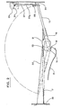
- the support 16 of the tubular arm 15 is connected by a spring 17 (Fig. 2) to a fixed point 38 of the chassis of the machine, so that it is normally stressed by this spring in the direction anti-clockwise (when looking at Fig. 2) to the position indicated by dashed lines.
- the support 16 is connected in this case to an element of a disengageable hub with a unidirectional effect 18, which is locked by means not shown in a position in which the arm 15 occupies the position shown in solid lines in FIG. 2.
- this disengageable hub can be unlocked by means of the lever 14, and it is mounted so that the arm 15 can then undergo a free angular movement in the counterclockwise direction, to pass from the position illustrated in solid lines to that shown in dashed lines in FIG. 2.
- the second element of the disengageable hub 18 is wedged on the output shaft 19 of a reduction gear 20, the input shaft of which carries a pulley 21.
- the element of the disengageable hub with unidirectional effect 18 connected to the arm 15, 16 can rotate freely in one direction relative to the element connected to the shaft 19, but it is positively driven by this shaft 19 when the latter rotates in clockwise when looking at Fig. 2.
- the tying string 22 which comes from a string box (not shown) provided in a manner known per se on the press, is wrapped at least once around the pulley 21 and then passes through the arm tubular string guide 15, its end being indicated at 22a in FIG. 2.
- These members include a bearing surface or anvil 23 fixed to the press in the vicinity of the orifice for entering the harvested products, on the side corresponding to the rest position of the twine guide arm 15, 16.
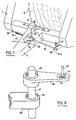
- a knife 24 intended to cooperate with this anvil 23 is pivotally mounted about a fixed axis 25 (Fig. 3 and 4). In its rest position in which it is spaced from the anvil 23 (Fig. 3), this knife rests by its rear part against a stop 26.
- the front part of the knife is connected by a coupling rod 27 at one end a lever with two arms 28 pivotally mounted towards its middle about an axis 29.
- the lever 11 acts on the detector 12 to cause, through the cable 13, the displacement of the unlocking lever 14 associated with the disengageable hub 18. Due to this release, the spring 17 acts by traction on the arms 15, 16 to rotate rapidly in the anticlockwise direction and to bring it into the position shown in broken lines in F ig. 2.As soon as the twine guide arm 15, 16 has left the lever 28, the latter switches clockwise, looking at FIGS. 3, 4 to separate the knife 24 from the anvil 23, which releases the string. Thus, when the arm 15, 16 has reached a rapid pivoting movement under the effect of the spring 17 in the position indicated in phantom in FIG.
- the string hangs freely in front of the orifice 5 for the entry of harvested products into the press. Its end is then gripped by these products and driven, so that traction is exerted on this string to tend to take it in order to ensure binding, in a manner known per se.
- the arm 15, 16 Towards the end of its pivoting movement, the arm 15, 16 abuts against the lever 28 and causes it to tilt counterclockwise (looking at FIGS. 3 and 4), which, via the coupling rod 27, causes the knife 24 to pivot about its axis 25, this knife thus cutting the string 22, which reached between the anvil 23 and the knife 24 as a result of its guidance by the arm 15, 16, maintaining its end against the anvil 23 in a visible manner in Fig. 4.
- the device is thus returned to its rest position in which it will remain until the binding of the next ball.
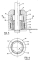
- the shaft 19 is journalled dans'ce body 30 by a smooth bearing 31. It has a part 32 of hexagonal shape, arranged in the upper half of the body 30. Rollers or rollers 33 are mounted between the faces of this part 32 of the shaft and the inner periphery of the body 30, and they are retained by a cage 34.
- this cage 34 extends downward in the lower part of the body 30 to constitute the inner element of a freewheel comprising an outer ring 35 of which the locking lever 14 and the rollers or needles 36 are integral, ring 35 being journalled in the body 30 by a plain bearing 37.
- the lower freewheel 34, 35, 36 of this hub disengageable allows the locking lever 14 to keep the same position in space, since it is not driven in the normal direction of rotation of the shaft 19, while allowing control of the cage for the return from the twine guide arm to its starting position.
- the disengaging hub is then reset automatically by rotating the shaft 19, which "catches up” with the rollers or rollers 33.
- FIG. 7 we see that we have designated by the reference 1, as in FIG. 1, the body of a cylindrical baler supported by wheels 2, this press being here again intended to be coupled to a tractor by means of a drawbar 3.
- Also indicated at 8 is the ball formed by winding inside the press chamber, in a conventional manner.
- the twine guide arm 15 is, as indicated above, mounted so as to move by its free end 15a in a transverse movement relative to the direction of movement of the press, to ensure by this transverse scanning effect the binding of the ball 8 when the formation thereof is completed.
- this arm 15 is connected to a one-way coupling 18 combined with a trigger arm 14 which can be actuated itself by a cable 13 when the ball has reached its maximum diameter.
- the arm 15 is here again subjected to the effect of a spring 17 mounted between said arm and a hooking point 38 provided on the chassis of the press.
- the unidirectional coupling 18 is driven, during the binding operation, by an axis or shaft 19.
- the drive of the arm 15 for its transverse sweeping movement in order to ensure the binding is provided by an electric motor 41 which drives the shaft 19 constituting the input shaft of the coupling unidirectional 18 by means of a reduction gear designated as a whole by the reference 42 in FIG. 7.
- the reducer versible 42 comprises, in the embodiment considered, an input shaft 43 which can be the output shaft of the electric motor 41 or a shaft driven directly by the latter at high speed, for example by means of a bevel gear, this shaft carrying a cam 44 housed in a slot 45 of a shaft 46 pivotally mounted on a shaft 47 which can correspond to the input shaft 19 of the coupling with one-way effect or be connected directly to this one.
- a coupling forming a freewheel 48 is provided between the lever 46 and the shaft 47.
- This shaft 47 is further journaled in a fixed support 49 carried by the gearbox 42, with the interposition of another coupling forming a freewheel 50.
- the two freewheel couplings are mounted in the same direction so that, when the lever 46 undergoes pivoting under the effect of the cam 44 cooperating with the slot 45, it drives the shaft in a pivoting direction 47 in rotation, while it rotates freely on this shaft during its pivoting in the other direction, any return movement of the shaft 47 being then prevented by the second coupling forming freewheel 50. A shifting of the shaft in the direction corresponding to this return movement is also prevented when the shaft 43 is stopped.
- FIG. 9 an electrical circuit for supplying the electric motor 41. It is provided here on the press, as visible in FIG. 7 a circuit-breaker switch 51 which is opposite the rest position of the twine guide arm and a circuit-breaker switch 52 which corresponds to this rest position, as visible in the drawings.
- the power supply is shown diagrammatically at 53, which can be supplied by a battery provided on the press or directly by the electrical circuit of the tractor.
- the supply conductor 53 is connected by a conductor 54 to a pad of the contactor 51, the other pad of which is grounded at 55 by a conductor 56, through a relay winding 57.
- the contacts of the relay 57 are connected, on the one hand, by a conductor 58 to one terminal of the motor 41, the other terminal of which is earthed at 59, and on the other hand, by a conductor 60, to a pad of the contactor 52, the other pad of which is connected to the supply conductor 53 by a conductor 61.
- a reaction circuit is established by a conductor 62 between conductors 56 and 58.
- the cable 13 is actuated by the tractor driver or automatically to move the arm 14 and unlock the coupling 18.
- the twine guide arm 15 is then moved under the effect of the spring 17, from the rest position shown in FIG. 7 to its starting position, in which its free end 15a is on the opposite side of the press.
- the stop switch 52 closes. Arriving at the other end of its travel or in its starting position, the arm 15 acts on the switching contactor 51 to close it. This completes a circuit between the power supply 53 and the earth at 55 by the conductor 54, the contactor 51, the conductor 56 and the relay 57.
- the excitation of the relay 57 closes its contacts and also establishes a circuit from the supply at 53 to earth at 59 by conductor 61, closed contactor 52, conductor 60, closed contacts of relay 57, conductor 58, motor 41 and earth at 59.
- FIG. 10 There is shown in FIG. 10 an alternative embodiment in which the drive of the twine guide arm is ensured from the PTO shaft of the tractor or from a shaft connected thereto.
- Fig. 10 we have designated by the same references as above the elements of the press, which are shown simply schematically.
- the body 1 of the press is extended forwards by a drawbar 3 and supports a unidirectional coupling 18, the release arm 14 of which can be actuated by a cable 13, this coupling being connected to a twine guide arm 15 which here again is subjected to the action of a spring 17.
- This reducer comprises, as before, two couplings forming freewheels mounted in the same direction, in order to provide the desired irreversibility character for the tree 68.
- a bent lever designated by 70 is pivotally mounted on the press around an axis or pivot 71.
- This lever comprises a first arm 72 provided with a stop 73 which can be applied against the lever 67 to maintain the friction surface 66 away from the cam 65.
- the lever 70 also comprises a second arm 74 which is connected to a spring 75 connected by its other end to a rod 76 actuating a knife 77 cooperating with an anvil 78.
- the spring 75 acts on the rod 76 to maintain in the closed position the knife 77 retaining the end of the string, in a manner in itself conventional.
- the cable 13 causes, via the arm 14, the unlocking of the coupling 18, which releases the twine guide arm 15 and allows the spring 17 to bring this arm into its starting position, in which its free end is on the opposite side of the press.
- the arm 15 moves away from the spring 75, the latter acts to rotate the lever 70 counterclockwise around the axis 71, so that the stop 73 moves away from the lever 67, the surface of friction 66 then being applied against the cam 65.
- the spring 75 also releases the rod 76, which ensures the opening of the knife 77 to allow the end of the string to escape.
- the lever 67 undergoes a back-and-forth pivoting of small amplitude thanks to a return spring (not shown).
- the first freewheel coupling of the reducer 69 acts to rotate the shaft 68, and this shaft is immobilized by the second freewheel coupling of this reducer during the movement of return of the lever 67.
- the arm 15 is thus moved in a slow pivoting movement by the unidirectional coupling 18, to provide the transverse scanning necessary for tying.
Landscapes
- Life Sciences & Earth Sciences (AREA)
- Environmental Sciences (AREA)
- Basic Packing Technique (AREA)
Applications Claiming Priority (4)
| Application Number | Priority Date | Filing Date | Title |
|---|---|---|---|
| FR8101138 | 1981-01-22 | ||
| FR8101138A FR2498048A1 (fr) | 1981-01-22 | 1981-01-22 | Dispositif de liage pour presses a balles cylindriques |
| FR8104466A FR2500997B2 (fr) | 1981-01-22 | 1981-03-06 | Dispositif de liage pour presses a balles cylindriques |
| FR8104466 | 1981-03-06 |
Publications (3)
| Publication Number | Publication Date |
|---|---|
| EP0057122A2 true EP0057122A2 (de) | 1982-08-04 |
| EP0057122A3 EP0057122A3 (en) | 1983-01-19 |
| EP0057122B1 EP0057122B1 (de) | 1985-05-15 |
Family
ID=26222192
Family Applications (1)
| Application Number | Title | Priority Date | Filing Date |
|---|---|---|---|
| EP19820400056 Expired EP0057122B1 (de) | 1981-01-22 | 1982-01-13 | Bindevorrichtung für Rundballenpressen |
Country Status (3)
| Country | Link |
|---|---|
| EP (1) | EP0057122B1 (de) |
| DE (2) | DE3263447D1 (de) |
| FR (1) | FR2500997B2 (de) |
Cited By (3)
| Publication number | Priority date | Publication date | Assignee | Title |
|---|---|---|---|---|
| US4656931A (en) * | 1984-11-21 | 1987-04-14 | New Holland Inc. | Apparatus for automatically wrapping round bales |
| FR2604857A1 (fr) * | 1986-10-10 | 1988-04-15 | Rivierre Casalis | Procede et dispositif de commande de bras de guidage de ficelle de liage de balles cylindriques dans une presse ramasseuse |
| US5054387A (en) * | 1990-04-23 | 1991-10-08 | Ford New Holland, Inc. | Apparatus for wrapping bales with twine |
Family Cites Families (6)
| Publication number | Priority date | Publication date | Assignee | Title |
|---|---|---|---|---|
| DE2530320C3 (de) * | 1974-07-17 | 1979-08-23 | Deere & Co., Moline, Ill. (V.St.A.), Niederlassung Deere & Co. European Office, 6800 Mannheim | Bindevorrichtung für Wickelballenpressen |
| US4024804A (en) * | 1975-11-17 | 1977-05-24 | Gehl Company | Rotary baling machine with twine feeding mechanism and articulated drive assembly |
| US4023479A (en) * | 1976-06-17 | 1977-05-17 | Sperry Rand Corporation | Twine wrapper with spring supplement for round bales |
| US4094239A (en) * | 1976-10-01 | 1978-06-13 | John Leroy Murr | Apparatus for cutting hay baler twine |
| DE2801309A1 (de) * | 1978-01-13 | 1979-07-19 | Claas Maschf Gmbh Geb | Verfahren und vorrichtung zum binden von rundballen aus landwirtschaftlichem erntegut |
| US4150614A (en) * | 1978-02-21 | 1979-04-24 | Schwartz Dale R | Automatic round bale wrapping assembly |
-
1981
- 1981-03-06 FR FR8104466A patent/FR2500997B2/fr not_active Expired
-
1982
- 1982-01-13 EP EP19820400056 patent/EP0057122B1/de not_active Expired
- 1982-01-13 DE DE8282400056T patent/DE3263447D1/de not_active Expired
- 1982-01-13 DE DE1982400056 patent/DE57122T1/de active Pending
Cited By (5)
| Publication number | Priority date | Publication date | Assignee | Title |
|---|---|---|---|---|
| US4656931A (en) * | 1984-11-21 | 1987-04-14 | New Holland Inc. | Apparatus for automatically wrapping round bales |
| FR2604857A1 (fr) * | 1986-10-10 | 1988-04-15 | Rivierre Casalis | Procede et dispositif de commande de bras de guidage de ficelle de liage de balles cylindriques dans une presse ramasseuse |
| EP0267821A1 (de) * | 1986-10-10 | 1988-05-18 | Rivierre Casalis | Verfahren und Vorrichtung zum Steuern von Schnurführungsarmen zum Binden von Rollballen in einer Rollballenpresse |
| US4885990A (en) * | 1986-10-10 | 1989-12-12 | Rivierre Casalis | Control of twine guide arm in a pickup baler |
| US5054387A (en) * | 1990-04-23 | 1991-10-08 | Ford New Holland, Inc. | Apparatus for wrapping bales with twine |
Also Published As
| Publication number | Publication date |
|---|---|
| FR2500997A2 (fr) | 1982-09-10 |
| FR2500997B2 (fr) | 1985-08-09 |
| DE57122T1 (de) | 1983-03-03 |
| DE3263447D1 (en) | 1985-06-20 |
| EP0057122B1 (de) | 1985-05-15 |
| EP0057122A3 (en) | 1983-01-19 |
Similar Documents
| Publication | Publication Date | Title |
|---|---|---|
| EP0064117B1 (de) | Ohne Unterbrechung arbeitende Rundballenpresse | |
| EP0046427B1 (de) | Bindeeinrichtung für Rundballenpressen | |
| EP0192904B1 (de) | Rundballenpresse mit Bindemechanismus | |
| EP0046426B1 (de) | Rundballenpresse | |
| EP0090120B1 (de) | Bindevorrichtung mittels zwei Bindfäden für Rundballenpresse | |
| EP0057122B1 (de) | Bindevorrichtung für Rundballenpressen | |
| EP0041444B1 (de) | Bindevorrichtung für Rundballenpresse | |
| EP1075175B1 (de) | Rundballenpresse mit integrierter wickelvorrichtung | |
| EP0217715A1 (de) | Ausstossvorrichtung für Rundballen | |
| EP0267821B1 (de) | Verfahren und Vorrichtung zum Steuern von Schnurführungsarmen zum Binden von Rollballen in einer Rollballenpresse | |
| FR2604856A1 (fr) | Presse a grosses balles pour produits de recoltes agricoles | |
| EP0041442A1 (de) | Bindevorrichtung für eine Rundballenpresse | |
| EP0717920B1 (de) | Fahrbare Maschine mit getriebenen Laufrädern wie Rasen- oder Buschmäher | |
| EP0137882B1 (de) | Bindevorrichtung für Rundballenpresse | |
| EP0064113B1 (de) | Binderbetätigungseinrichtung für Rundballenpresse | |
| EP0968643B1 (de) | Verteilmaschine | |
| EP0217714B1 (de) | Verfahren und Vorrichtung zum Binden von Ballen aus faserigem Erntegut | |
| EP0059815B1 (de) | Bindegarnsteuerung für eine Rundballenpresse | |
| EP0064116A1 (de) | Ohne Unterbrechung arbeitende Rundballenpresse | |
| EP0071687B1 (de) | Bindevorrichtung für Rundballenpressen | |
| EP0041443B1 (de) | Bindevorrichtung für Rundballenpresse | |
| FR2498048A1 (fr) | Dispositif de liage pour presses a balles cylindriques | |
| FR2579063A1 (fr) | Dispositif indicateur d'un defaut de chargement de la chambre de formation d'une balle roulee dans une presse-ramasseuse | |
| FR2678695A1 (fr) | Dispositif d'entrainement selectif d'un arbre de sortie au moyen d'un arbre moteur et machine pour distribuer les fourrages, qui en est equipee. |
Legal Events
| Date | Code | Title | Description |
|---|---|---|---|
| PUAI | Public reference made under article 153(3) epc to a published international application that has entered the european phase |
Free format text: ORIGINAL CODE: 0009012 |
|
| 17P | Request for examination filed |
Effective date: 19820119 |
|
| AK | Designated contracting states |
Designated state(s): DE FR GB IT NL |
|
| ITCL | It: translation for ep claims filed |
Representative=s name: LENZI & C. |
|
| TCNL | Nl: translation of patent claims filed | ||
| PUAL | Search report despatched |
Free format text: ORIGINAL CODE: 0009013 |
|
| AK | Designated contracting states |
Designated state(s): DE FR GB IT NL |
|
| DET | De: translation of patent claims | ||
| ITF | It: translation for a ep patent filed | ||
| GRAA | (expected) grant |
Free format text: ORIGINAL CODE: 0009210 |
|
| AK | Designated contracting states |
Designated state(s): DE FR GB IT NL |
|
| REF | Corresponds to: |
Ref document number: 3263447 Country of ref document: DE Date of ref document: 19850620 |
|
| PLBE | No opposition filed within time limit |
Free format text: ORIGINAL CODE: 0009261 |
|
| STAA | Information on the status of an ep patent application or granted ep patent |
Free format text: STATUS: NO OPPOSITION FILED WITHIN TIME LIMIT |
|
| 26N | No opposition filed | ||
| PGFP | Annual fee paid to national office [announced via postgrant information from national office to epo] |
Ref country code: NL Payment date: 19870131 Year of fee payment: 6 |
|
| PG25 | Lapsed in a contracting state [announced via postgrant information from national office to epo] |
Ref country code: NL Effective date: 19880801 |
|
| NLV4 | Nl: lapsed or anulled due to non-payment of the annual fee | ||
| GBPC | Gb: european patent ceased through non-payment of renewal fee | ||
| PG25 | Lapsed in a contracting state [announced via postgrant information from national office to epo] |
Ref country code: FR Free format text: LAPSE BECAUSE OF NON-PAYMENT OF DUE FEES Effective date: 19880930 |
|
| PG25 | Lapsed in a contracting state [announced via postgrant information from national office to epo] |
Ref country code: DE Effective date: 19881001 |
|
| PG25 | Lapsed in a contracting state [announced via postgrant information from national office to epo] |
Ref country code: GB Free format text: LAPSE BECAUSE OF NON-PAYMENT OF DUE FEES Effective date: 19881121 |
|
| REG | Reference to a national code |
Ref country code: FR Ref legal event code: ST |