EP0057144A2 - Maschine zum Verpacken von zylinderförmigen Artikeln in kreisförmigen Zuschnitten, geformt aus Bahnen von thermoplastischem Verpackungsmaterial - Google Patents
Maschine zum Verpacken von zylinderförmigen Artikeln in kreisförmigen Zuschnitten, geformt aus Bahnen von thermoplastischem Verpackungsmaterial Download PDFInfo
- Publication number
- EP0057144A2 EP0057144A2 EP82400121A EP82400121A EP0057144A2 EP 0057144 A2 EP0057144 A2 EP 0057144A2 EP 82400121 A EP82400121 A EP 82400121A EP 82400121 A EP82400121 A EP 82400121A EP 0057144 A2 EP0057144 A2 EP 0057144A2
- Authority
- EP
- European Patent Office
- Prior art keywords
- packaging
- fixed
- plate
- head
- fixed plate
- Prior art date
- Legal status (The legal status is an assumption and is not a legal conclusion. Google has not performed a legal analysis and makes no representation as to the accuracy of the status listed.)
- Granted
Links
- 238000004806 packaging method and process Methods 0.000 title claims abstract description 67
- 229920001169 thermoplastic Polymers 0.000 title 1
- 239000004416 thermosoftening plastic Substances 0.000 title 1
- 238000007789 sealing Methods 0.000 claims abstract description 16
- 239000005021 flexible packaging material Substances 0.000 claims description 7
- 239000000463 material Substances 0.000 claims description 6
- 238000012856 packing Methods 0.000 claims description 6
- 238000004891 communication Methods 0.000 claims description 5
- 230000000295 complement effect Effects 0.000 claims description 5
- 210000005069 ears Anatomy 0.000 claims description 3
- 238000013519 translation Methods 0.000 claims description 3
- 239000012815 thermoplastic material Substances 0.000 claims description 2
- 238000003466 welding Methods 0.000 claims description 2
- 230000014616 translation Effects 0.000 claims 2
- 239000005022 packaging material Substances 0.000 abstract description 8
- 230000000284 resting effect Effects 0.000 abstract description 2
- 238000012546 transfer Methods 0.000 description 6
- 235000013351 cheese Nutrition 0.000 description 4
- 240000002129 Malva sylvestris Species 0.000 description 3
- 235000006770 Malva sylvestris Nutrition 0.000 description 3
- 230000000903 blocking effect Effects 0.000 description 3
- 238000009434 installation Methods 0.000 description 3
- XEEYBQQBJWHFJM-UHFFFAOYSA-N Iron Chemical compound [Fe] XEEYBQQBJWHFJM-UHFFFAOYSA-N 0.000 description 2
- 229910052782 aluminium Inorganic materials 0.000 description 2
- XAGFODPZIPBFFR-UHFFFAOYSA-N aluminium Chemical compound [Al] XAGFODPZIPBFFR-UHFFFAOYSA-N 0.000 description 2
- 239000002781 deodorant agent Substances 0.000 description 2
- 229910052751 metal Inorganic materials 0.000 description 2
- 239000002184 metal Substances 0.000 description 2
- 229920003023 plastic Polymers 0.000 description 2
- 239000000725 suspension Substances 0.000 description 2
- 239000000853 adhesive Substances 0.000 description 1
- 239000004927 clay Substances 0.000 description 1
- 238000006073 displacement reaction Methods 0.000 description 1
- 230000008030 elimination Effects 0.000 description 1
- 238000003379 elimination reaction Methods 0.000 description 1
- 239000011521 glass Substances 0.000 description 1
- 229910052742 iron Inorganic materials 0.000 description 1
- 238000002372 labelling Methods 0.000 description 1
- 238000012423 maintenance Methods 0.000 description 1
- 239000004033 plastic Substances 0.000 description 1
- 230000000717 retained effect Effects 0.000 description 1
- 238000005096 rolling process Methods 0.000 description 1
- 239000000523 sample Substances 0.000 description 1
- 238000005476 soldering Methods 0.000 description 1
- 125000006850 spacer group Chemical group 0.000 description 1
- 230000001360 synchronised effect Effects 0.000 description 1
- XLYOFNOQVPJJNP-UHFFFAOYSA-N water Substances O XLYOFNOQVPJJNP-UHFFFAOYSA-N 0.000 description 1
Images


Classifications
-
- B—PERFORMING OPERATIONS; TRANSPORTING
- B26—HAND CUTTING TOOLS; CUTTING; SEVERING
- B26F—PERFORATING; PUNCHING; CUTTING-OUT; STAMPING-OUT; SEVERING BY MEANS OTHER THAN CUTTING
- B26F1/00—Perforating; Punching; Cutting-out; Stamping-out; Apparatus therefor
- B26F1/38—Cutting-out; Stamping-out
- B26F1/3846—Cutting-out; Stamping-out cutting out discs or the like
-
- B—PERFORMING OPERATIONS; TRANSPORTING
- B65—CONVEYING; PACKING; STORING; HANDLING THIN OR FILAMENTARY MATERIAL
- B65B—MACHINES, APPARATUS OR DEVICES FOR, OR METHODS OF, PACKAGING ARTICLES OR MATERIALS; UNPACKING
- B65B11/00—Wrapping, e.g. partially or wholly enclosing, articles or quantities of material, in strips, sheets or blanks, of flexible material
- B65B11/54—Wrapping by causing the wrapper to embrace one end and all sides of the contents, and closing the wrapper onto the opposite end by forming regular or irregular pleats
Definitions
- the invention relates to machines for packaging objects of substantially cylindrical shape, such as cheeses, ribbons wound with sticky paper or for a typewriter, deodorant blocks for sanitary purposes, etc., and more particularly relates to machines for packaging these objects in sheets cut according to closed contours, preferably convex, such as circular discs, in strips of flexible packaging material, such as paper, aluminum and films of transparent or non-transparent plastic material and possibly heat-sealable, the sheet preferably able to be regularly pleated around the perimeter of the object.
- a diaphragm device partially seals the sleeve by folding the packaging sheet over one of the faces of an object, after the latter has been disposed by its other face against the part of the sheet closing the central openings. packing heads applied against each other, then pushed with this sheet into the socket by a movable plunger, until it comes to rest against a support plate perpendicular to the axis of the socket. A sealing member is introduced into the socket and applied through the diaphragm to the part of the packaging sheet folded over the object resting against the support plate, after the movable pusher has been withdrawn from the socket.
- the packaging heads are provided on their opposite faces with complementary radial teeth, to initiate a pleating of a sheet which they enclose, so as to pack the object in a pleated sheet at its periphery , the axis common to the packaging heads and to the sleeve being vertical, and the movable head being disposed above the fixed head.
- Packing machines of this type must be supplied on the one hand with objects to be packaged, on the other hand with cut sheets, either manually or automatically for one and / or the other of these operations.
- a machine for cutting thin sheets according to closed contours in strips of packaging material comprising, on the one hand, for enclosing a strip of packaging material, two trays, one of which is fixed and has a slot having the shape of the closed contour to be cut out , and the other of which is movable and has a groove on the face opposite the first, this groove coming to be superimposed on the slot along the closed contour, when the two plates are applied one against the other, and, d on the other hand, for cutting this sheet, a cutting tool, carried by a mobile assembly following the layout of the closed contour, and movable in a direction perpendicular to the plates between a cutting position in which the tool crosses the slot and is engaged in the groove, and a rest position in which the tool is not engaged in the groove.
- the fixed plate When the closed contour, common to the slot and the groove is circular, the fixed plate consists of a central circular disc surrounded by a fixed plate and carried by a fixed shaft, serving as a pivot for the movement of the crew mobile and guide for the movement perpendicular to the cutting tool plate.
- suction nozzles in the central disc are provided, these nozzles being connected to a vacuum chamber arranged in this disc, and put in Communication with a vacuum pump.
- the transfer of the cut sheet from the cutting machine to the packaging machine is ensured by the sliding, on at least one slide going from one to the other of these machines, of a suction probe, carried by a tubular arm, and capable of moving between a position inside the contour, in which it is engaged in a notch of the movable plate and placed in communication with the source of vacuum while the connection of the latter with the nozzles is cut, and a position outside the contour, plumb with the lower pleating and packaging head of the associated packaging machine, on which the cut sheet is deposited as soon as the connection with the vacuum source is cut.
- suction nozzles on the plate stationary cutting machine, near and around the slot, the operation of these nozzles must be synchronized with the step-by-step advance of the strip of packaging material on the fixed plate of the cutting machine.
- the maximum operating rate of an installation associating the two aforementioned machines is determined from the lowest of the maximum rates of these two machines, and taking into account the non-negligible duration of the transfer of a sheet. cut from the cutting machine to the packaging machine, which constitutes a significant limitation in the operation of such an installation, in particular for large diameter discs, which can hang on the mechanism for advancing the strip of material packaging on the fixed plate of the cutting machine.
- such an installation is bulky and difficult to adjust since the two associated machines must operate in synchronism.
- the machine according to the invention is more than a space requirement. limited, of a simplified structure and adjustment, and authorizing increased rates due in particular to the elimination of any phase of transfer of the cut sheets from one station to another.
- This machine according to the invention also makes it possible to cut large area sheets and to pack bulky objects while having a simple structure.
- the packaging machine is characterized in that it also comprises, on the one hand, for gripping the strips of flexible packaging material, a fixed plate, having a central opening whose shape corresponds to that of the outline of the leaves, and whose section is slightly larger than that of sheets, as well as a movable pressure plate, arranged parallel to the fixed plate, and having, on its face opposite the fixed plate, a groove having the shape of the outline of the leaves and coming opposite the central opening of the fixed plate, when the pressure plate is applied against the latter, the pressure plate also having a central opening, internal to the groove, allowing the passage of the movable packaging head, and, on the other hand, for cutting a sheet in a strip pressed between the fixed and presser plates, a mobile assembly, following the outline of the outline of the sheets around the fixed packaging head, disposed in the central opening of the fixed plate, slightly set back on the side of the latter opposite to that against which the pressing plate is applied, and a cutting tool, carried by the mobile
- the cutting tool is integral with a yoke pivotally mounted on the outer end of the radial arm, around a radial axis perpendicular to the axis of rotation of the ring rotating, and a roller is mounted in rotation in the yoke around a second radial axis, perpendicular to the axis of rotation of the ring, for rolling on a ring surrounding the rotating ring with play, and displaceable in translation according to the axis of rotation of the ring, in order to control the position of the cutting tool.
- the axial position of the ring which controls the position of the cutting tool, is itself controlled by jacks to which the ring is resiliently biased.
- the pressure plate has, on its face opposite the fixed plate, and between its groove and its central opening, a plurality of suction nozzles opening into at least one annular channel placed in communication with a vacuum source, for pressing the part of the strip of flexible packaging material closing the central opening of the fixed plate against the pressure plate.
- the strip of flexible material is held and moved between the fixed plate and the pressure plate by a step-by-step feed device, comprising at least one pair of pliers, capable of being moved on slides along the fixed plate by at least one fork, pivotally mounted around an axis transverse to the direction of movement of the strip on the fixed plate, and maneuvered by a jack.
- a step-by-step feed device comprising at least one pair of pliers, capable of being moved on slides along the fixed plate by at least one fork, pivotally mounted around an axis transverse to the direction of movement of the strip on the fixed plate, and maneuvered by a jack.
- the facing faces of the packaging heads are provided with complementary radial teeth to initiate pleating of a sheet which they enclose, so as to pack the object in a pleated sheet at its periphery, the axis common to the packaging heads and to the sleeve being vertical, the movable head being disposed above the fixed head, likewise the pressure plate is disposed above the fixed plate.
- the mobile packaging head of the machine is suspended with lost travel, on the rods of jacks mounted on gantries secured to the mobile pressure plate, on either side of the mobile packaging head, by means of diametrically opposite legs having openings through which the rods of r ins, the ends of which carry lug driving stops, which are shaped as ears against bends to connect to the face of the movable head not turned towards the fixed head.
- the movable pressure plate is mounted to slide along columns connecting to the fixed plate fixed sleepers carrying jacks for controlling the movement of the pressure plate towards the fixed plate, by their rods provided at their free end with spherical caps co-operating with imprints of the movable pressure plate, which is resiliently biased towards the fixed sleepers by springs bearing on the one hand against the fixed plate, and on the other hand against the bottom of sleeves carried by lateral legs of the pressure plate and crossed with guidance by the columns.
- the support plate is mounted at the end of a rod of a jack and can be introduced by the latter into the socket, until its bearing surface is at the level of the central opening of the fixed packaging head, then pushed back with the object by the movable pusher, the stroke of which is limited so that the object is introduced into the sleeve beyond the diaphragm device, the plate support being immobilized in this position by a blocking system during the operations of the diaphragm device and the sealing member, then moved to remove the packaged object from the sleeve and place it on the path of a ejection bringing the object to an evacuation station.
- the movable pusher may be in the form of an annular piston moved by a cylinder eccentric relative to the axis of the packaging heads, the sealing member being axially displaceable through the annular piston by an axial cylinder parallel to the eccentric cylinder.
- the sealing member can be a welding head, if the flexible material of emballa- g e is a thermoplastic material, or a label holders, capping the packaged object to deposit thereon a self-adhesive label, in other cases.
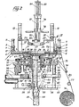
- the machine comprises a fixed plate 1, horizontal and rectangular, pierced with a circular central opening 2, of section slightly greater than that of circular sheets or discs in which objects of substantially cyclindrical shape, such as only cheeses, must be packaged.
- This fixed plate 1 also has, along the major part of its long sides, two grooves 3, and each at its four corners, a mounting hole for a vertical guide column 4.
- a movable pressure plate 5, disposed horizontally above the fixed plate 1 is slidably mounted in the vertical direction by four side tabs 6, integral with the four corners of the pressure plate 5, and each mounted on a sleeve 7, crossed by one of the columns ensuring the fixing above the fixed plate 1 of two fixed crosspieces 8.
- Each sleeve 7 is received in a hole in the corresponding tab 6 and has at its lower end an external radial flange 9 which is housed in a countersink surrounding the hole in the tab 6 on its underside.
- the bottom of each sleeve 7 has a guide bore on a column 4 and a spring 10, surrounding the column 4, bears against the fixed plate 1 and against the bottom of the sleeve 7 to raise the pressure plate 5 above the plate fixed 1.
- the rods of the cylinders 11 carry, at their end lower free, spherical caps 12 supported in imprints of corresponding shapes formed on the upper face of the pressure plate 5.
- the latter also has a central circular opening 13, coaxial with the central opening 2 of the fixed plate 1, but of section lower than this.
- a circular groove 14, corresponding to the layout of the sheets to be cut, is formed in the underside of the pressure plate 5, and opens directly above the opening 2 of the fixed plate 1, as shown in FIG. 3
- suction nozzles 16 communicating with an annular channel 17 machined in the pressure plate 5 and capable of being itself placed in communication with a source of vacuum (not shown), open onto the underside of the pressure plate 5.
- These nozzles 16 are produced by fine holes in a sheet metal closing the annular channel on the underside of the plate 5.
- the packaging and pleating head 22 is in the form of a circular crown coaxial with the central opening 13 of the pressure plate 5, and of an external diameter less than the diameter of the opening 13.
- the lower face of this head 22 has a slightly frustoconical general shape and has a radial toothing 23, the suspension lugs 20 are attached to the upper face of the movable head 22 by bent ears 24 so that the operation of the jacks 19 makes it possible to move the movable head 22 through the central opening 13 of the pressure plate 5, to bring it to cooperate with a fixed lower packaging and pleating head 25.
- the latter is also in the form of a circular ring coaxial with the central openings 2 and 13 of the fixed plates 1 and presser 5 and the movable head 22. Its external diameter is slightly greater than that of the opening 13 of the presser plate 5, and its upper face, inclined towards its central opening 26, which is the same diameter as the central opening 27 of the movable head 22, has a slightly frustoconical female shape, complementary to the male frustoconical shape of the underside of the movable head 22, as well as a radial toothing 28, complementary with play of that 23 of the movable head 22.
- the fixed head 25 is arranged under the fixed plate 1, so that the periphery of its upper face is located in the opening 2.
- the underside of the fixed head 25 is extended by a socket in two parts 29 and 30, coaxial with the openings, 2, 13, 26 and 27 respectively of the plates 1 and 5 and the heads 25 and 22, and of the same internal diameter as the openings 26 and 27, and which corresponds to a diameter slightly greater than that of the cylindrical objects to be packaged.
- a ring 31 is rotatably mounted around the upper part 29 of the sleeve, thanks to a bearing 07 supported by a spacer 32 bearing on the edge of a central opening of a fixed upper horizontal deck 33 carried by four uprights 34 plumb with a fixed horizontal lower deck 35.
- the ring 31 is driven by a belt 36 passing through the groove of a pulley 37 mounted on the axis of a motor 38, suspended under the deck 33.
- the rotating ring 31 carries a radial arm 39, shown in more detail in FIG. 5.
- This arm 39 is provided, at its internal end, with a curved foot 40, by which the arm 39 is screwed onto the face upper of the ring 31, and at its outer end, of a support 41, on which a yoke 42 is pivotally mounted about a substantially radial axis 43 perpendicular to the axis of rotation of the ring 31.
- a roller 44 is rotatably mounted in the yoke 42 around a fixed radial axis 45 and also perpendicular to the 'axis of rotation of the ring 31, so that the roller 44 can roll on a flat ring 47, mounted with play around the ring 31, when the latter is rotated.
- a cutting blade 46 is secured to the external part of the yoke 42, and points upwards.
- the flat ring 47 rests by three imprints of its lower face on spherical caps 48 carried at the free upper end of the rods of three jacks 49 suspended from the deck 33 by their cylinders and the flat ring 47 is recalled towards this deck 33 by three tension springs 50.
- a diaphragm device 51 is located between the two parts 29 ′ and 30 of the sleeve, and fixed under the bulkhead 33.
- This diaphragm device of the so-called "iris” type, is known per se, and comprises a rotary disc provided with slots in spiral portiors in each of which engages a stud fixed to a radially movable rod and ending in a blade, the various blades overlapping in scales, so that in the open position of the diaphragm, these blades are separated and completely release the axial passage of the sleeve, while in the closed position, the blades determine a limited axial passage.
- This device well known, and whose rotary disc is moved by a jack, is not shown in detail.
- a circular support plate 52 of section slightly smaller than that of the sleeve, is carried at the free upper end of the rod of a long-stroke rectilinear axial cylinder 53, the cylinder of which is suspended under the lower apron 35
- Under the support plate 52 is suspended a flattened counter-rod 54 parallel to the cylinder rod 53, and passing through a lumen 55 formed in the deck 35 and in a stirrup 56, carrying a blocking cylinder 57 capable to immobilize the counter rod 54, and therefore the support plate 52, by the exit of its rod applying a brake piston 58 against a flat part of this counter rod 54, itself clamped against a branch of the stirrup 56.
- the jack 53 raises the support plate 52 so that its upper surface is at the level of the opening 26 of the fixed packing and pleating head 25, while in the maximum rod retracted position, the upper surface of this support plate 52 is brought to the level water from an evacuation slide 59, practically connecting to the plate 52 by a circular cut.
- An ejection pusher 60 maneuvered by an ejection cylinder 61, the cylinder of which is clamped on a cross 62 between two uprights 34, allows the transfer to the evacuation slide 59 of any object carried by the support plate 52 in its lower position.
- Two lateral forks 63 pivotally mounted about a horizontal and transverse axis 64 by their lower ends, and each retained in a yoke 65 displaced longitudinally by a jack 66 articulated on the lower apron 35, each surround their teeth with a stud 67, projecting laterally, of pliers 68, the body 69 of which slides longitudinally along two slides 70, the lower jaw 71 of which is received in the corresponding groove 3 of the fixed plate 1, and the upper jaw 72 of which carries a jack 73 pinching against the lower jaw 71.
- the pair of tongs 68 with the forks 63 and the actuating cylinders 66 constitute a device for advancing step by step a strip of packaging material introduced between the fixed plate 1 and presser 5, and of which a length useful for cutting a circular packaging sheet is unwound by a transverse lever 74, pivotally mounted by its lateral arms on fasteners 75 integral with the deck upper 33, and maneuvered by a jack (not shown) in synchronism with a braking device of a unwinding drum 76 mounted on a transverse axis.
- a bracket 78 supports two rectilinear and parallel jacks, one of which is eccentric and carries, at the free lower end of its rod, a pusher in the form of annular piston 80, capable of being lowered into the bushing to a level slightly below the diaphragm 51, and the other 81 of which is axial and carries at the free lower end of its rod a sealing member 82 which can pass through the annular piston 80, which is a soldering iron, if the packaging material is heat-sealable, or a label holder of known type, in the opposite case, which debits the labels one by one.
- the rods of the cylinders 79 and 8 1 pass through their cylinder right through, and two dice 83 are keyed at their upper end.
- These dice 8 3 are each provided with a rectangular notch which embraces one side of a vertical rectangular guide bar 84, fixed between the heads of the cylinders of the jacks 79 and 81, so that their rods cannot rotate around their respective axes.
- the machine operates as follows: the strip 85 of the flexible packaging material is unwound from the drum 76 passing over a guide roller 77, by the operation of the rocker 74, which releases the brake of the drum 76 while the clamps 68 hold the strip 85 on the fixed plate 1.
- the rocker 74 has unrolled a length sufficient for cutting a sheet, and this length is driven and held by the step-by-step advance device between the raised pressure plate 5 and the fixed plate 1, while the brake of the drum 76 is applied.
- the pressing plate 5 is then lowered by the jacks 11 against the band 85 which it clamps on the fixed plate 1, while the movable head 22 remains raised.
- the suction nozzles 16 press against the pressure plate 5 a part of the strip 85 covering the opening 2 of the fixed plate 1, so as to tighten the strip 85 well.
- the cutting blade 46 driven in rotation with the rotating ring 31 around the fixed head 25, is then lifted by lifting the flat ring 47 controlled by the jacks 49, which causes the blade 46 to pass through the opening 2 of the fixed plate 1, and to engage in the groove 14 of the pressure plate 5, by cutting without burrs in the strip 85 a circular sheet of packaging. Then the jacks 49 and the springs 50 recall the flat ring 47 downwards, which brings the cutting blade 46 back to the rest position, released from the groove 14.
- the mobile packing and pleating head 22 is then lowered by the jacks 19 onto the fixed head 25. Thanks to its lost-stroke suspension, the mobile head 22, at the end of its travel, only rests by its weight on the head fixed 25 by pinching the sheet on it, without tearing or creasing it.
- the cooperating teeth 23 and 28 of the packaging and pleating heads 22 and 25 thus initiate pleating of the periphery of the sheet, while the central part of this sheet closes the opening 26 of the fixed head 25, and is located supported by the support plate 52 raised in the high position.
- An object to be packaged such as a cheese
- an automatic device for example of the well-known type with suction cup
- the jack 79 controls the descent of the annular piston 80, which is applied against the upper face of the object, then pushes it with the sheet that the object covers with its lower face in the socket by pushing the support plate 52, the jack 53 then being supplied at low pressure.
- the periphery of the sheet slides between the teeth of the heads 22 and 25, then along the internal lateral surface of the sleeve.
- the annular piston 80 When the annular piston 80 has completed its entire stroke, the upper face of the object is positioned slightly under the diaphragm 51, and the locking cylinder 57 controls the immobilization of the support plate 52 in the corresponding position.
- the maximum stroke of the annular piston 80 being defined, it is the thickness of the object which thus determines the position in which the support plate 52 is locked.
- the annular piston 80 is then removed from the sleeve, and the diaphragm 31 is closed by folding the periphery of the sheet which projects above the object on the upper face of the latter, accentuating the pleating of this already primed sheet. by the cooperating teeth of the heads 22 and 25.
- the diameter of the axial passage delimited by the closed diaphragm 51 is comparable to that of the annular piston 80, so that the descent of the sealing member, controlled by the jack 81, allows the closed packaging to be closed around of the object by the sheet regularly pleated and folded over this object.
- the pleated packaging sheet may be made of heat-sealable plastic, of paper, or of metal (aluminum) coated with such a material.
- This sheet can also be made of plain paper, and the sealing can then be ensured by the application of a label supplied by a distributor associated with an appropriate head, mounted at the lower end of the rod of the jack 81. It is also possible that a label be placed on the heat-sealed closure of the packaging.
- the sealing member 82 is raised to the initial position, and the movable head 22 and the pressure plate 5 can also be raised to the initial position, following a stroke which, although small (for example 10 mm) / is clearly sufficient for the step-by-step advance device to be able to position and block on the fixed plate 1 a new length of strip of packaging material, previously unwound by the rocker 74, and necessary for cutting a new sheet, the cut strip 85 being taken up by a friction reel or force-limiting drum (not shown) driven in rotation.
- the blocking cylinder 57 releases the counter rod 54 and the support plate 52 is brought back by the cylinder 53 to the lower position (shown in dotted lines in FIG. 2).
- the ejection cylinder 6 1 then maneuvers the ejection pusher 60, which transfers the packaged object 86 to the evacuation slide 59, then returns to the initial position, and the support plate 52 is then brought back to the high position. , at the opening 26 of head 25 for a new cycle.
- the invention is not limited to the embodiment which has just been described . It is possible, for example, to replace the jaw clamps of the step-by-step advancement device with grippers with electromagnetic operation and movable back and forth along the grooves 3 of the fixed plate 1. In known manner, these clamps can also be replaced by intermittently rotating rollers. Similarly, the movement of the flat ring 47 can be ensured by a fork control. It should be noted that the vertical displacement bringing the cutting blade into the cutting position can also be ensured by an electromagnet disposed on the radial arm driven by the rotating ring or by a small jack, for example pneumatic. In addition, the automatic object feeding device which can be associated with the machine, must be adapted to the nature and consistency of the objects.
- a clamp device such as that described and represented in FIGS. 1 and 3 in French patent N ° 73,05026 in the name of the Applicant, can perfectly replace the suction cup device for transferring objects from a conveyor supply to the packaging and pleating heads 22 and 25.
- a bucket and gripper device as described and shown in the figures in French patent No. 77 38951 will also be used. on behalf of the Applicant.
- the machine according to the present invention makes it possible, on a single station, to cut the packaging sheets and to pack the objects in these sheets. It is possible, by means of the machine according to the present invention, to pack not only products such as cheeses, tapes of sticky paper or of typewriter, or deodorant blocks already mentioned, but also to pack in pleated sheets, possibly t ran sparentes, pots, boxes and other objects ra f - g there are glass, clay, sandstone, in particular to protect their labeling or their closures.
Landscapes
- Engineering & Computer Science (AREA)
- Mechanical Engineering (AREA)
- Life Sciences & Earth Sciences (AREA)
- Forests & Forestry (AREA)
- Packaging Of Special Articles (AREA)
- Containers And Plastic Fillers For Packaging (AREA)
- Wrapping Of Specific Fragile Articles (AREA)
- Basic Packing Technique (AREA)
- Making Paper Articles (AREA)
- Wrappers (AREA)
Priority Applications (1)
| Application Number | Priority Date | Filing Date | Title |
|---|---|---|---|
| AT82400121T ATE13649T1 (de) | 1981-01-26 | 1982-01-22 | Maschine zum verpacken von zylinderfoermigen artikeln in kreisfoermigen zuschnitten, geformt aus bahnen von thermoplastischem verpackungsmaterial. |
Applications Claiming Priority (2)
| Application Number | Priority Date | Filing Date | Title |
|---|---|---|---|
| FR8101366A FR2498557B1 (fr) | 1981-01-26 | 1981-01-26 | Machine a emballer des objets de forme sensiblement cylindrique dans des feuilles decoupees selon un contour ferme dans des bandes d'un materiau souple d'emballage |
| FR8101366 | 1981-01-26 |
Publications (3)
| Publication Number | Publication Date |
|---|---|
| EP0057144A2 true EP0057144A2 (de) | 1982-08-04 |
| EP0057144A3 EP0057144A3 (en) | 1982-08-18 |
| EP0057144B1 EP0057144B1 (de) | 1985-06-05 |
Family
ID=9254488
Family Applications (1)
| Application Number | Title | Priority Date | Filing Date |
|---|---|---|---|
| EP82400121A Expired EP0057144B1 (de) | 1981-01-26 | 1982-01-22 | Maschine zum Verpacken von zylinderförmigen Artikeln in kreisförmigen Zuschnitten, geformt aus Bahnen von thermoplastischem Verpackungsmaterial |
Country Status (5)
| Country | Link |
|---|---|
| EP (1) | EP0057144B1 (de) |
| AT (1) | ATE13649T1 (de) |
| DE (1) | DE3263959D1 (de) |
| ES (1) | ES509032A0 (de) |
| FR (1) | FR2498557B1 (de) |
Cited By (9)
| Publication number | Priority date | Publication date | Assignee | Title |
|---|---|---|---|---|
| FR2584334A1 (fr) * | 1985-07-05 | 1987-01-09 | Evrard Jacques | Machine a decouper les feuilles minces en disques |
| EP0468776A1 (de) * | 1990-07-24 | 1992-01-29 | Portals Engineering Limited | Verbesserungen von oder in Bezug auf Vorrichtungen zum Verpacken von Gegenständen |
| FR2730212A1 (fr) * | 1995-02-07 | 1996-08-09 | Ix Manu Sa | Machine d'emballage de produits individuels, installation de conditionnement et application correspondantes |
| CN103144789A (zh) * | 2013-03-13 | 2013-06-12 | 宁波舜宇光电信息有限公司 | 一种包铜箔作业的辅助治具及其包装方法 |
| CN103501932A (zh) * | 2011-01-20 | 2014-01-08 | 禹荣官 | 用于冲裁和包装元件板的装置 |
| CN103847995A (zh) * | 2014-02-24 | 2014-06-11 | 昆山安拓达自动化技术有限公司 | 一种包铜箔机 |
| CN105173163A (zh) * | 2015-10-12 | 2015-12-23 | 天津津树达机械有限公司 | 薄膜包装机 |
| CN114919812A (zh) * | 2022-06-09 | 2022-08-19 | 上海尚翱科技有限公司 | 一种茶饼自动化包装线 |
| CN117018883A (zh) * | 2023-08-16 | 2023-11-10 | 深圳市爱玛特科技有限公司 | 一种多壁碳纳米管复合超滤膜的制作工艺 |
Families Citing this family (2)
| Publication number | Priority date | Publication date | Assignee | Title |
|---|---|---|---|---|
| ES2049599B1 (es) * | 1991-10-04 | 1996-10-16 | Ser Gonzalez Clemente Del | "maquina envolvedora de productos horticolas" |
| IT1404243B1 (it) | 2011-01-21 | 2013-11-15 | Soremartec Sa | Procedimento per il confezionamento di un prodotto in un involucro ermetico di materiale in foglio |
Family Cites Families (6)
| Publication number | Priority date | Publication date | Assignee | Title |
|---|---|---|---|---|
| GB162531A (en) * | 1920-04-20 | 1921-05-05 | Forgrove Mach | Improvements in or relating to tablet-wrapping machines |
| US2656659A (en) * | 1950-12-26 | 1953-10-27 | Paper Art Company Inc | Bulk paper plate wrapping machine |
| GB710500A (en) * | 1951-03-09 | 1954-06-16 | Rose Brothers Ltd | Improvements in wrapping machines |
| FR2112734A5 (en) * | 1970-11-06 | 1972-06-23 | Evrard Jacques | Thin plastic films - are cut to produce discs using orbiting cutter blade |
| FR2217215A1 (de) * | 1973-02-13 | 1974-09-06 | Evrard Jacques | |
| FR2225336B1 (de) * | 1973-04-11 | 1977-08-05 | Evrard Jacques |
-
1981
- 1981-01-26 FR FR8101366A patent/FR2498557B1/fr not_active Expired
-
1982
- 1982-01-22 DE DE8282400121T patent/DE3263959D1/de not_active Expired
- 1982-01-22 EP EP82400121A patent/EP0057144B1/de not_active Expired
- 1982-01-22 AT AT82400121T patent/ATE13649T1/de not_active IP Right Cessation
- 1982-01-25 ES ES509032A patent/ES509032A0/es active Granted
Cited By (13)
| Publication number | Priority date | Publication date | Assignee | Title |
|---|---|---|---|---|
| FR2584334A1 (fr) * | 1985-07-05 | 1987-01-09 | Evrard Jacques | Machine a decouper les feuilles minces en disques |
| EP0468776A1 (de) * | 1990-07-24 | 1992-01-29 | Portals Engineering Limited | Verbesserungen von oder in Bezug auf Vorrichtungen zum Verpacken von Gegenständen |
| FR2730212A1 (fr) * | 1995-02-07 | 1996-08-09 | Ix Manu Sa | Machine d'emballage de produits individuels, installation de conditionnement et application correspondantes |
| CN103501932B (zh) * | 2011-01-20 | 2015-11-25 | 禹荣官 | 用于冲裁和包装元件板的装置 |
| CN103501932A (zh) * | 2011-01-20 | 2014-01-08 | 禹荣官 | 用于冲裁和包装元件板的装置 |
| CN103144789B (zh) * | 2013-03-13 | 2014-11-26 | 宁波舜宇光电信息有限公司 | 一种包铜箔作业的辅助治具及其包装方法 |
| CN103144789A (zh) * | 2013-03-13 | 2013-06-12 | 宁波舜宇光电信息有限公司 | 一种包铜箔作业的辅助治具及其包装方法 |
| CN103847995A (zh) * | 2014-02-24 | 2014-06-11 | 昆山安拓达自动化技术有限公司 | 一种包铜箔机 |
| CN105173163A (zh) * | 2015-10-12 | 2015-12-23 | 天津津树达机械有限公司 | 薄膜包装机 |
| CN114919812A (zh) * | 2022-06-09 | 2022-08-19 | 上海尚翱科技有限公司 | 一种茶饼自动化包装线 |
| CN114919812B (zh) * | 2022-06-09 | 2023-11-03 | 上海尚翱科技有限公司 | 一种茶饼自动化包装线 |
| CN117018883A (zh) * | 2023-08-16 | 2023-11-10 | 深圳市爱玛特科技有限公司 | 一种多壁碳纳米管复合超滤膜的制作工艺 |
| CN117018883B (zh) * | 2023-08-16 | 2024-04-19 | 深圳市爱玛特科技有限公司 | 一种多壁碳纳米管复合超滤膜的制作工艺 |
Also Published As
| Publication number | Publication date |
|---|---|
| EP0057144B1 (de) | 1985-06-05 |
| FR2498557B1 (fr) | 1985-11-08 |
| DE3263959D1 (en) | 1985-07-11 |
| ES8301807A1 (es) | 1983-01-01 |
| ES509032A0 (es) | 1983-01-01 |
| EP0057144A3 (en) | 1982-08-18 |
| FR2498557A1 (fr) | 1982-07-30 |
| ATE13649T1 (de) | 1985-06-15 |
Similar Documents
| Publication | Publication Date | Title |
|---|---|---|
| EP0295203B1 (de) | Verfahren zum Verpacken eines Produkts und Vorrichtung zur Ausübung des Verfahrens | |
| EP0467817B1 (de) | Rotierender Bogenausleger für die genaue Plazierung von blattförmigen Elementen auf flachen Trägern | |
| EP0284529B1 (de) | Verpackung für Produkte unter durchsichtiger Folie, deren Herstellung und Vorrichtung zum Herstellen derselben | |
| EP1312548B1 (de) | Vorrichtung zum Ausschneiden einer Reihe von Membranverschlüssen aus einer Bahn und zur Fixierung dieser auf einer Reihe von gefüllten Behältern | |
| FR2558438A1 (fr) | Produit conditionne et procede et appareil de conditionnement d'articles | |
| EP0057144B1 (de) | Maschine zum Verpacken von zylinderförmigen Artikeln in kreisförmigen Zuschnitten, geformt aus Bahnen von thermoplastischem Verpackungsmaterial | |
| JPS5940684B2 (ja) | ロ−ル包装装置 | |
| EP0000851B1 (de) | Automatische Vorrichtung zum Zerteilen eines thermoplastischen Schlauches und zum Überziehen von Behältern mittels dieser Schlauchteilen | |
| EP0559512B1 (de) | Vorrichtung zum Verschliessen von Behältern durch Heisssiegeln von Deckeln und Anlage mit einer solchen Vorrichtung | |
| EP0146482B1 (de) | Verfahren und Vorrichtung zum Anbringen von Griffen oder Versteifungselementen auf schlauchartigen Bändern | |
| FR3057204A1 (fr) | Machine pour la production de recipients en boite a fond et/ou couvercle composes d'une base semblable a un disque et d'une surface laterale definie par une bande ou ceinture raccordee au perimetre de la base semblable a un disque | |
| EP0069011B1 (de) | Vorrichtung zum Anbringen und Zentrieren eines thermoplastischen Schlauches um Gegenstände durch ein vertikales mit schwebenden Dorn versehenes Element | |
| FR2765191A1 (fr) | Procede et machine de collage automatique d'un film plastique thermoretractable sur le fond d'une caisse ouverte | |
| FR2518052A1 (fr) | Machine et procede pour produire des emballages du type sac | |
| FR2484979A1 (fr) | Procede et appareil d'assemblage de matiere en feuille, notamment pour alimenter en continu des imprimantes rapides | |
| EP0331596B1 (de) | Verfahren zum automatischen Herstellen von einem mit einem Etikett bekleideten Behälter, insbesondere Behälter mit rundem Querschnitt, und Vorrichtung zur Durchführung dieses Verfahrens | |
| FR2692566A3 (fr) | Dispositif de jonction automatique des extrémités de deux nappes de matière. | |
| EP0004631B1 (de) | Verpackungsvorrichtung und -verfahren | |
| EP0519142B1 (de) | Vorrichtung zum Zuführen und Ablegen eines biegsamen Etiketts in eine Form auf einen geformten Gegenstand | |
| CH664742A5 (fr) | Procede d'emballage de produits et dispositif pour la mise en oeuvre de ce procede. | |
| FR2557491A1 (fr) | Machine pour la coupe et la pose de troncons de ruban souple | |
| JPH082090Y2 (ja) | 包装材切開除去装置 | |
| FR2518054A1 (fr) | Installation pour la pose d'un groupe d'objets, tels que des boites de conserve sur un support en vue de leur emballage | |
| BE885346A (fr) | Procede et appareil de preparation d'emballages hermetiques pour produits etalables et emballages hermetiques ainsi obtenus | |
| FR2623470A1 (fr) | Machine a conditionner des matieres en bande, notamment des bardes |
Legal Events
| Date | Code | Title | Description |
|---|---|---|---|
| PUAI | Public reference made under article 153(3) epc to a published international application that has entered the european phase |
Free format text: ORIGINAL CODE: 0009012 |
|
| PUAL | Search report despatched |
Free format text: ORIGINAL CODE: 0009013 |
|
| AK | Designated contracting states |
Designated state(s): AT CH DE GB IT NL |
|
| AK | Designated contracting states |
Designated state(s): AT CH DE GB IT NL |
|
| 17P | Request for examination filed |
Effective date: 19830210 |
|
| ITF | It: translation for a ep patent filed | ||
| GRAA | (expected) grant |
Free format text: ORIGINAL CODE: 0009210 |
|
| AK | Designated contracting states |
Designated state(s): AT CH DE GB IT LI NL |
|
| PG25 | Lapsed in a contracting state [announced via postgrant information from national office to epo] |
Ref country code: NL Effective date: 19850605 Ref country code: AT Effective date: 19850605 |
|
| REF | Corresponds to: |
Ref document number: 13649 Country of ref document: AT Date of ref document: 19850615 Kind code of ref document: T |
|
| REF | Corresponds to: |
Ref document number: 3263959 Country of ref document: DE Date of ref document: 19850711 |
|
| NLV1 | Nl: lapsed or annulled due to failure to fulfill the requirements of art. 29p and 29m of the patents act | ||
| PG25 | Lapsed in a contracting state [announced via postgrant information from national office to epo] |
Ref country code: LI Effective date: 19860131 Ref country code: CH Effective date: 19860131 |
|
| PLBE | No opposition filed within time limit |
Free format text: ORIGINAL CODE: 0009261 |
|
| STAA | Information on the status of an ep patent application or granted ep patent |
Free format text: STATUS: NO OPPOSITION FILED WITHIN TIME LIMIT |
|
| 26N | No opposition filed | ||
| REG | Reference to a national code |
Ref country code: CH Ref legal event code: PL |
|
| GBPC | Gb: european patent ceased through non-payment of renewal fee | ||
| PG25 | Lapsed in a contracting state [announced via postgrant information from national office to epo] |
Ref country code: GB Effective date: 19881121 |
|
| PG25 | Lapsed in a contracting state [announced via postgrant information from national office to epo] |
Ref country code: DE Effective date: 19891003 |