EP0057347A2 - Heizautomat - Google Patents
Heizautomat Download PDFInfo
- Publication number
- EP0057347A2 EP0057347A2 EP82100088A EP82100088A EP0057347A2 EP 0057347 A2 EP0057347 A2 EP 0057347A2 EP 82100088 A EP82100088 A EP 82100088A EP 82100088 A EP82100088 A EP 82100088A EP 0057347 A2 EP0057347 A2 EP 0057347A2
- Authority
- EP
- European Patent Office
- Prior art keywords
- automatic heater
- heater according
- induced draft
- retort
- draft fan
- Prior art date
- Legal status (The legal status is an assumption and is not a legal conclusion. Google has not performed a legal analysis and makes no representation as to the accuracy of the status listed.)
- Granted
Links
Images



Classifications
-
- F—MECHANICAL ENGINEERING; LIGHTING; HEATING; WEAPONS; BLASTING
- F23—COMBUSTION APPARATUS; COMBUSTION PROCESSES
- F23B—METHODS OR APPARATUS FOR COMBUSTION USING ONLY SOLID FUEL
- F23B90/00—Combustion methods not related to a particular type of apparatus
- F23B90/04—Combustion methods not related to a particular type of apparatus including secondary combustion
- F23B90/06—Combustion methods not related to a particular type of apparatus including secondary combustion the primary combustion being a gasification or pyrolysis in a reductive atmosphere
-
- F—MECHANICAL ENGINEERING; LIGHTING; HEATING; WEAPONS; BLASTING
- F23—COMBUSTION APPARATUS; COMBUSTION PROCESSES
- F23L—SUPPLYING AIR OR NON-COMBUSTIBLE LIQUIDS OR GASES TO COMBUSTION APPARATUS IN GENERAL ; VALVES OR DAMPERS SPECIALLY ADAPTED FOR CONTROLLING AIR SUPPLY OR DRAUGHT IN COMBUSTION APPARATUS; INDUCING DRAUGHT IN COMBUSTION APPARATUS; TOPS FOR CHIMNEYS OR VENTILATING SHAFTS; TERMINALS FOR FLUES
- F23L17/00—Inducing draught; Tops for chimneys or ventilating shafts; Terminals for flues
- F23L17/005—Inducing draught; Tops for chimneys or ventilating shafts; Terminals for flues using fans
Definitions
- the invention relates to an automatic heater with retort firing for open hot water heaters, closed heating systems and low-pressure steam systems.
- the problem of the combustion of flame gas coal lies in the emission or in the blackening of the exhaust plume when the induced draft fan is switched off.
- the object of the invention is therefore to avoid such emissions.
- the invention is based on the consideration that the heating device works at intervals. After reaching the flow temperature set on a thermostat, for example, the induced draft fan is switched off.
- the ember bed refurbished for the downtime in the retort furnace is then only supplied with little combustion air via the natural chimney draft.
- the coals In the transition zone from the degassed ember core on the grate to the green fuel in front of the retort, the coals begin to smolder, so that the exhaust gases become very black when there is a lack of oxygen. Here Bacharach 8 is observed for minutes.
- Bacharach describes a method for determining the soot tar number of the emission from a furnace.
- a quantity of exhaust gas of 90 liters is extracted from the exhaust gas to be examined using a special sampling device at a constant suction speed of 4 m / s - based on an exhaust gas temperature of 320 ° C. and a barometer reading of 753 Torr Glass fiber filter sleeve headed.
- the carbon dioxide content of the exhaust gases must be measured in the connector immediately after sampling.
- the dust, soot and tar content in milligrams per normal cubic meter of exhaust gas, based on a carbon dioxide content of 12%, is to be determined from the determined weight of the sample collected in the filter sleeve.
- the measurement begins three minutes after a quantity of fuel, which corresponds to at least one third of the filling volume of the furnace, has been applied to an embers layer sufficient for ignition; the tensile strength must not be throttled. In the case of mechanically charged firing systems, the measurement must be carried out at the highest firing performance.
- the automatic controller In systems with only automatic control, the automatic controller, in the other cases the manual controller, must be opened completely. Then basic embers are to be produced. In the case of underburning fires, the basic embers must extend to the lower edge of the filling shaft. In the case of burn-through firing, the basic ember height should be approximately 15 cm.
- the basic embers are produced when the filter paper strip no longer stains in the method described below.
- An automatic sampling device with sampling probe serves as the measuring device.
- the automatic sampling device removes 0.15 1 + 0.01 1 sample gas from the connector at intervals of one minute in a measuring time of 6 seconds and pass it through a filter paper strip; here arises from in the sample dust, soot and tar constituents contained in gas, a corresponding sequence of circular color spots of 0.312 cm 2 .
- the color spots are to be evaluated using the comparison scale described below. The measurement begins with the fuel feed and ends as soon as the filter paper strip is no longer discernible.
- the reflectivity of the white cotton filter paper must be checked with an ELEPHO device, using magnesium oxide with a reflectivity of 99.2% using a blue filter R 457 as a comparison standard.
- the comparison scale consists of 80 fields of different colors, arranged in a flat rectangular coordinate system. The fields are labeled on the abscissa with the numbers O to 9 and on the ordinate with the letters A to H.
- the comparison scale is printed on paper,
- the degree of reflection of the fields of the comparison scales must be determined using a Densomat with a Densopak top density measuring head.
- an Agfa-Gevaert Repro blue filter 552 must be placed between the light source and the color field.
- the other color fields of the comparison scale result from the fact that the soot comparison scale is printed parallel to the abscissa from B to H and the tar comparison scale parallel to the ordinate from 1 to 9.
- Each color field has an area of 20 mm x 20 mm; the color field is provided with a circular cutout of 6 mm in diameter in the middle.
- the color fields are printed on the paper so that the impression of a filter paper color spot is created.
- Each color spot on the filter paper strip is assigned to the color field on the comparison scale that corresponds to its color and is to be rated with the number of the color field.
- the soot tar number is the arithmetic mean of these numbers.
- the soot tar number can also be determined according to DIN 18 890 sheets. In addition to the black and white tones, white and brown tones are also recorded.
- the emissions are prevented by the fact that smoldering gases formed between the switch-on times of the fan are afterburned. This is preferably done with suction of the carbonization gases that are produced during the usual downtimes. These smoldering gases are then mixed with combustion air and re-introduced into the combustion chamber for post-combustion.
- Nozzles are arranged at the retort outlet for blowing in the mixture of carbonization gas and combustion air or only for additionally blowing in combustion air.
- the nozzles are preferably combined in a nozzle tube with nozzles offset from the combustion chamber. In narrow fireboxes, blowing through one nozzle pipe into each side water is sufficient.
- the extraction of the smoldering gases and the intake of combustion air and their mixing is advantageously carried out by using a second induced draft fan. This induced draft fan blows the mixture of extracted carbonisation gas and sucked-in combustion air into the nozzle pipe for post-combustion.
- Particularly favorable extraction conditions for the carbonization gas result when the carbonization gases are extracted from the intake ports of the induced draft fan which is usually provided for operating the automatic heater with retort firing. At this point, the smoldering gases can be collected in a bundle.
- an automatic heater operated in this way has Bacharach 1 - 2 in all operating states.
- the automatic heater according to Figures 1 - 3 is designed as standard for open hot water heating according to DIN 4751 sheet 1 and can be used in a modification for closed heating systems as well as for low pressure steam systems.
- the automatic heater differs from conventional boiler types by space-saving dimensions, to which automatic retort firing 1 and fuel storage 2 outside the boiler contribute.
- the retort furnace 1 is provided twice. Each furnace 1 is assigned a suction 2 with a fan 3. Likewise, each furnace 1 is provided with special feed 4 and 5 ash removal. The furnaces 1, the feeds 4 and the suction 2 can each be controlled differently in combination. This creates a double firing with a total of 9 different switching options, which guarantee a high degree of safety, since in any case half the nominal heat output is always available.
- the automatic heater consists of a boiler body 6 made of sheet steel, which forms a unit on the heating gas and water side.
- the boiler body contains two independently working fires stanchions 1 with loading device 4 and ash removal device 5. Both furnaces are also assigned separate heating surfaces. If the secondary heating surface is common, the firing is separated by a vertical water pocket, not shown.
- the charging devices 1 are separated from one another in terms of switching and control technology, so that either individual operation with one firing is possible. For the rest, a common regulation is provided for both furnaces 1 and an equal loading of the furnaces can thereby be achieved.
- both combustion chambers assigned to the furnaces 1 have a nominal heat load of 500 kW.
- the heater operates as follows.
- Coke or coal is fed from a bunker 2 onto a U-shaped conveyor trough 7 of an oscillating conveyor of the loading device 4. This is done via appropriate funnels and sliders of the bunker 2.
- the U-shaped conveyor trough 7 is made of rustproof and abrasion-resistant steel and is located below the bunker 2. It is provided with an electrohydraulic drive that max. Can move 100 mm back and forth. From the U-shaped conveyor trough 7, the coke or coal arrives in front of a feed tappet 8, which is optionally moved together with the conveyor trough 7. The amplitude is dimensioned according to the desired flow of coke or coal.
- the feed tappet 8 pushes the coal or coke into the inclined combustion chamber of the retort furnace 1.
- the gradient is between 20 and 25 °.
- the furnace, ie the retort is water-cooled on all sides.
- the charging device 4 works at shorter or longer intervals.
- an air-cooled grate 9 made of easily replaceable segments is provided in the bottom of the retort of the retort firing 1.
- By inflow of the induced draft fan 3 sucked air takes place on the grate and in the retort an optimal combustion.
- the fuel ignited at the beginning of the grate 9 gradually moves on by pressing in fresh coal or fresh coke.
- the furnace 1 and the suction 2, 3, the performance of the heater can be varied, for example, in the following manner.
- the coke or the coal is completely burned out.
- the slag (ashes) falls automatically into airtight ashtrays of ash removal 5.
- the garbage cans are normally to be changed every two days.
- the heating gases flowing through the retort of the retort furnace 1 are deflected sharply at the end of the retort. Any coarse-grained solid particles that are entrained are separated out and fall into the garbage cans. In a subsequent calming chamber 10, the fine-grained solids contained in the heating gas also largely fail. On their way along secondary heating surfaces 11, the heating gases largely give off their sensible heat, the boiler water flowing through the cooling rooms of the secondary heating surfaces.
- the automatic heater allows a minimum output of about 5% of the nominal heat output and is thus far below the minimum output of conventional automatic heaters.
- an adaptation to a very low heat requirement is also advantageously possible.
- the furnace 1 takes only a few minutes due to a very small embers volume. This enables high demands for comfort. Thanks to precisely matched combustion air and fuel quantities and the elasticity of the furnace, an extremely high boiler efficiency of 85% at nominal heat output can be achieved. The high efficiency in combination with extreme adaptation to changing loads enables extremely economical continuous operation.
- the automatic heater according to the invention according to FIGS. 4 + 5 differs from the automatic heater according to FIGS. 1-3 by a different arrangement and designated 11 Induced draft fan, which has the function of the induced draft 2 and blower 3 according to FIGS. 1-3.
- the gases generated in the automatic heater are drawn off via rear, hollow side cheeks 20.
- the side cheeks 20 are shown in FIG. 5 as lying in front of the section line AB with dashed lines.
- the gases enter the side cheeks at 21 and are drawn off by the suction fan 11 at the bottom.
- a nozzle tube 13 is arranged in the region of the upper deflection tongue 12 of the retort.
- the nozzle tube 13 is welded to the deflection tongue 12 of the retort and has a number of nozzles arranged offset from the combustion chamber.
- the nozzle tube 13 is also cooled by the water of the deflection tongue 12. This ensures an adequate lifespan.
- the smoldering gases generated during the idle time of the induced draft fan 11 are sucked off by means of a second induced draft fan 14 in the intake port of the induced draft fan 11 via a line 15.
- combustion air is drawn in via an intake port 16.
- the combustion air sucked in is mixed with the carbonization gas extracted. This mixture is pressed by the induced draft fan 14 into the nozzle tube 13 and enters the combustion chamber from its nozzles, so that the carbonization gases can be combusted.
- the suction line 15 and the suction nozzle 16 can be controlled by flaps which can be actuated together via a mechanism which is shown schematically in FIG.
- the induced draft fan 11 After reaching a flow temperature set on the thermostat, the induced draft fan 11 is switched off. At the same time, the induced draft fan 14 switches on, and a servomotor opens the control flaps in the suction line 15 and in the combustion air intake socket 16.
- the induced draft fan 11 is switched on again via the thermostats and, at the same time, the induced draft fan 14 is switched off and the control motor closes both control flaps again.
- the resulting emission values are shown in FIG. 6.
- the representation is based on a measurement according to DIN 18 890 sheet 10.
- the diagram also contains the suction times of the induced draft fan for primary air and that of the 2nd fan for secondary air.
- the improvement in the solid emissions is aptly presented.
- the running time of the secondary air fan begins with the downtime of the primary air fan.
- the switching times are performance-dependent and are approximately the same for gas coal and crushed coke 4. When coke 4 is burned, the secondary air fan is switched off.
Landscapes
- Engineering & Computer Science (AREA)
- Chemical & Material Sciences (AREA)
- Combustion & Propulsion (AREA)
- Mechanical Engineering (AREA)
- General Engineering & Computer Science (AREA)
- Physics & Mathematics (AREA)
- Thermal Sciences (AREA)
- Regulation And Control Of Combustion (AREA)
Abstract
Description
- Die Erfindung betrifft einen Heizautomaten mit Retorten- feuerung für offene Warmwasserheizungen, geschlossene Heizsysteme und Niederdruckdampfanlagen.
- Bei derartigen Heizautomaten liegt die Problematik der Verfeuerung von Gasflammkohle in der Emission bzw. in der Schwärzung der Abgasfahne bei ausgeschaltetem Saugzugventilator. Der Erfindung liegt daher die Aufgabe zogrunde, derartige Emissionen zu vermeiden. Dabei geht die Erfindung von der Überlegung aus, daß der Heizautc-mat in Intervallen arbeitet. Nach Erreichen der beispielsweise an einem Thermostaten eingestellten Vorlauftemperatur wird der Saugzugventilator abgeschaltet. Das für die Stillstandszeit in der Retortenfeuerung aufgearbeitete Glutbett wird.dann nur noch über den natürlichen Schornsteinzug mit wenig Verbrennungsluft versorgt. In der Übergangszone vom entgasten Glutkern auf dem Rost zum grünen Brennstoff vor der Retorte beginnen die Kohlen zu schwelen, so daß unter Sauerstoffmangel eine starke Schwärzung der Abgase eintritt. Hierbei wird minutenlang Bacharach 8 beobachtet.
- Bacharach bezeichnet ein Verfahren zur Bestimmung der Ruß-Teer-Zahl der von einer Feuerung ausgehenden Emission. Dabei wird aus dem zu untersuchenden Abgas mittels eines speziellen Probenahmegerätes bei einer konstanten Ansauggeschwindigkeit von 4 m/s - bezogen auf eine Abgastemperatur von 3200 C und einem Barometerstand von 753 Torr - eine Abgasmenge von 90 Liter entnommen und durch eine Glasfaser-Filterhülse geleitet. Der Kohlendioxidgehalt der Abgase ist unmittelbar nach der Probenahme im Verbindungsstück zu messen. Aus dem festgestellten Gewicht der in der Filterhülse gesammelten Probe ist der Staub-, Ruß- und Teergehalt in Milligramm pro Normalkubikmeter Abgas, bezogen auf einen Kohlendioxidgehalt von 12 % zu bestimmen.
- Bei handbeschickten Feuerungsanlagen beginnt die Messung drei Minuten, nachdem eine Brennstoffmenge, die mindestens einem Drittel des Füllrauminhalts der Feuerungsanlage entspricht, auf eine für die Entzündung ausreichende Glutschichthöhe aufgegeben worden ist; die Zugstärke darf nicht gedrosselt sein. Bei mechanisch beschickten Feuerungsanlagen ist die Messung bei höchster Feuerungsleistung vorzunehmen.
- Bei Anlagen mit alleiniger Automatik-Regelung ist der automatische Regler, in den übrigen Fällen der Handregler, vollständig zu öffnen. Anschließend ist Grundglut herzustellen. Bei Unterbrandfeuerungen muß die Grundglut bis zur Unterkante des Füllschachtes reichen. Bei Durchbrandfeuerungen soll die Grundgluthöhe etwa 15 cm betragen.
- Die Grundglut ist hergestellt, wenn bei der nachfolgend beschriebenen Methode keine Färbung des Filterpapierstreifens mehr auftritt.
- Nach Herstellen der Grundglut sind 2,5 kg Brennstoff aufzugeben.
- Als Meßgerät dient ein automatisches Probenahmegerät mit Probenahmesonde. Dem Abgas sind mit dem automatischen Probenahmegerät in Abständen von einer Minute in einer Meßzeit von 6 Sekunden 0,15 1 + 0,01 1 Probegas aus dem Verbindungsstück zu entnehmen und durch einen Filterpapierstreifen zu leiten; hierbei entsteht durch die im Probegas enthaltenen Staub-, Ruß- und Teerbestandteile eine entsprechende Folge von kreisförmigen Farbflecken von 0,312 cm2. Die Farbflecke sind mittels nachfolgend beschriebener Vergleichsskala auszuwerten. Die Messung beginnt mit der Brennstoffaufgabe und endet, sobald keine Färbung des Filterpapierstreifens mehr erkennbar ist.
- Es ist ein weißes Baumwollfilterpapier mit einem Reflexionsvermögen von 85 % + 2,5 % zu verwenden, das einen Strömungswiderstand von 200 bis 800 mm Wassersäule bei einer Filtenflächenbelastung von 3 Normalliter pro Quadratzentimeter und Minute besitzt.
- Die Prüfung des Reflexionsvermögens des weißen Baumwollfilterpapiers hat mit einem ELEPHO-Gerät zu erfolgen, wobei als Vergleichsstandard Magnesiumoxid mit einem Reflexi.-- onsvermögen von 99,2 % unter Einsetzung eines Blaufilters R 457 zu verwenden ist.
- Die Vergleichsskala besteht aus 80 Feldern verschiedener Farbe, die in einem ebenen rechtwinkligen Koordinatensystem angeordnet sind. Die Felder sind auf der Abszisse mit den Zahlen O bis 9 und auf der Ordinate mit den Buchstaben A bis H bezeichnet. Die Vergleichsskala ist auf Papier gedruckt,
- Die Felder O,A bis 9,A bilden die Rußvergleichsskala. Das Feld O,A hat das volle Reflexionsvermögen des Untergrundes, die Felder 1,A bis 9,A sind in der Reflexion abgestuft nach der Gleichung
- R = 1,5 e - 0,091 RZ- 0,5
- R = Reflexionsgrad
- RZ = Rußzahl.
- Die Felder O,A bis O,H bilden die Teervergleichsskala. Das Feld O,A hat das volle Reflexionsvermögen des Untergrundes, die Felder B,O bis H,O sind in der Reflexion abgestuft nach der Gleichung
- 0,1743 TZ R = 1,25 . e - 0,25
- R = Reflexionsgrad
- TZ = Teerzahl.
- Die Bestimmung des Reflexionsgrades der Felder der Vergleichsskalen hat mit einem Densomaten mit Aufsichtsdichtemeßkopf Densopak zu erfolgen. Zur Ermittlung der Reflexionsgrade der Teervergleichsskala ist zwischen Lichtquelle und Farbfeld ein Agfa-Gevaert-Repro-Blaufilter 552 zu setzen.
- Die übrigen Farbfelder der Vergleichsskala entstehen dadurch, daß die Rußvergleichsskala parallel zur Abszisse von B bis H und die Teervergleichsskala parallel zur Ordinate von 1 bis 9 übereinander gedruckt sind. Jedes Farbfeld hat eine Fläche von 20 mm x 20 mm; das Farbfeld ist in der Mitte mit einem kreisförmigen Ausschnitt von 6 mm Durchmesser versehen.
- Die Farbfelder sind so auf das Papier aufgedruckt, daß der Eindruck eines Filterpapierfarbflecks entsteht.
- Jeder Farbfleck des Filterpapierstreifens ist dem Farbfeld der Vergleichsskala zuzuordnen, das seiner Färbung entspricht, und mit der Zahl des Farbfeldes zu bewerten.
- Die Ruß-Teerzahl ist der arithmetische Mittelwert dieser Zahlen.
- Die Ruß-Teerzahl läßt sich auch nach DIN 18 890 Blatt ermitteln. Dabei werden zusätzlich zu den den Schwarz-Weiß-Tönen auch Weiß-Braun-Töne erfaßt.
- Beim Einschalten des Saugzugventilators werden die noch in den Heizgaszügen befindlichen Schwelgase ausgetrieben. Danach nimmt die Schwärzung ab und ist schon nach wenigen Minuten bis auf Bacharach 2 abgefallen.
- Nach der Erfindung werden die Emissionen dadurch verhindert, daß zwischen den Einschaltzeiten des Ventilators entstehende Schwelgase nachverbrannt werden. Vorzugsweise geschieht das unter Absaugung der während der üblichen Stillstandszeiten entstehenden Schwelgase. Diese Schwelgase werden dann mit Verbrennungsluft vermischt und zur Nachverbrennung erneut in den Feuerungsraum eingetragen.
- Zum Einblasen des Gemisches aus Schwelgas und Verbrennungsluft oder auch nur zum zusätzlichen Einblasen von Verbrennungsluft sind am Retortenausgang Düsen angeordnet. Vorzugsweise sind die Düsen in einem Düsenrohr mit zum Feuerraum versetzten Düsen zusammengefaßt. Bei schmalen Feuerräumen genügt das Einblasen durch je ein Düsenrohr in den seitlichen Wassert schen. Die Absaugung der Schwelgase und Ansaugung von Verbrennungsluft und deren Vermischung erfolgt vorteilhaft durch den Einsatz eines zweiten Saugzugventilators. Dieser Saugzugventilator bläst das Gemisch aus abgesaugtem Schwelgas und angesaugter Verbrennungsluft zur Nachverbrennung in das Düsenrohr.
- Besonders günstige Absaugungsverhältnisse für das Schwel-gas ergeben sich bei einer Absaugung der Schwelgase aus den Ansaugstutzen des zum Betrieb des Heizautomaten mit Retortenfeuerung üblicherweise vorhandenen Saugzugventilators. An dieser Stelle können die Schwelgase gebündelt erfaßt werden.
- Im Ergebnis hat ein so betriebener Heizautomat bei allen Betriebszuständen Bacharach 1 - 2.
- In der Zeichnung sind ein die Basis für die Erfindung bildender Heizautomat und ein erfindungsgemäßer Heizautomat dargestellt. Es zeigen:
- Figuren 1 - 3: Verschiedene Ansichten des die Basis bildenden Heizautomaten,
- Figuren 4 + 5: Den erfindungsgemäßen Heizautomaten.
- Figur 6: Eine schematische Darstellung der Feststoffemission.
- Der Heizautomat nach Figur 1 - 3 ist serienmäßig für offene Warmwasserheizungen nach DIN 4751 Blatt 1 ausgelegt und kann in Abwandlung für geschlossene Heizsysteme sowie für Niederdruck-Dampfanlagen eingesetzt werden. Der Heizautomat unterscheidet sich von üblichen Heizkesselbauarten durch raumsparende Abmessungen, zu denen eine automatische Retortenfeuerung 1 und eine Brennstofflagerung 2 außerhalb des Heizkessels beitragen. Die Retorten-Feuerung 1 ist doppelt vorgesehen. Jeder Feuerung 1 ist ein Saugzug 2 mit Gebläse 3 zugeordnet. Desgleichen ist jede Feuerung 1 mit besonderer Beschickung 4 und Entaschung 5 versehen. Die Feuerungen 1, die Beschickungen 4 und der Saugzug 2 sind in Kombination jeweils verschieden steuerbar. Dadurch entsteht eine doppelte Feuerung mit insgesamt 9 verschiedenen Schaltmöglichkeiten, die ein hohes Maß an Sicherheit gewährleisten, da in jedem Fall die halbe Nennwärmeleistung immer zur Verfügung steht.
- Der Heizautomat besteht aus einem aus Stahlblech gefertigten Kesselkörper 6, der heizgas- und wasserseitig eine Einheit bildet. Auf der anderen Seite beinhaltet der Kesselkörper zwei unabhängig von einander arbeitende Feuerungen 1 mit Beschickungseinrichtung 4 und Entaschungseinrichtung 5. Beiden Feuerungen sind ferner separate Heizflächen zugeordnet. Bei gemeinsamer Nachschaltheizfläche sind die Feuerungen durch eine senkrechte, nicht dargestellte Wassertasche getrennt. Die Beschickungseinrichtungen 1 sind schalt- und regeltechnisch voneinander getrennt, so daß wahlweise ein Einzelbetrieb mit einer Feucrung möglich ist. Im übrigen ist eine gemeinsame Regelung für beide Feuerungen 1 vorgesehen und kann dadurch eine gleiche Belastung der Feuerungen erreicht werden. Im Ausführungsbeispiel haben beide den Feuerungen 1 zugeordnete Feuerräume eine Nennwärmebelastung von 500 kW. Im einzelnen arbeitet der Heizautomat wie folgt.
- Aus einem Bunker 2 wird Koks bzw. Kohle auf eine U-förmige Förderrinne 7 eines Schwingförderers der Beschickungseinrichtung 4 gegeben. Das geschieht über entsprechende Trichter und Schieber des Bunkers 2. Die U-förmige Förderrinne 7 besteht aus nichtrostendem und abriebfestem Stahl und befindet sich unterhalb des Bunkers 2. Sie ist mit einem elektrohydraulischen Antrieb versehen, der sie in Längsrichtung max. 100 mm hin und her bewegen kann. Aus der U-förmigen Förderrinne 7 gelangt der Koks bzw. die Kohle vor einen Beschickungsstößel 8. Der wird wahlweise gemeinsam mit der Förderrinne 7 bewegt. Die Amplitude ist entsprechend dem jeweils gewünschten Förderstrom an Koks bzw. Kohle bemessen.
- Der Beschickungsstößel 8 schiebt die Kohle bzw. den Koks in den schrägliegenden Feuerungsraum der Retortenfeuerung 1. Die Steigung beträgt zwischen 20 und 25°. Der Feuerungsraum, d.h. die Retorte ist allseitig wassergekühlt. In Abhängigkeit von der benötigten Kesselleistung arbeitet die Beschickungseinrichtung 4 in kürzeren oder längeren Intervallen. Im Boden der Retorte der Retortenfeuerung 1 ist ein luftgekühlter Planrost 9 aus leicht auswechselbaren Segmenten vorgesehen. Durch Einströmen der von dem Saugzugventilator 3 angesaugten Luft findet auf dem Rost und in der Retorte eine optimale Verbrennung statt. Der am Anfang des Rostes 9 gezündete Brennstoff wandert durch Nachdrücken frischer Kohle bzw. frischen Kokses allmählich weiter. Durch unterschiedliche Betätigung der Beschickungseinrichtung 4, der Feuerung 1 und der Saugzüge 2, 3 läßt sich die Leistung des Heizautomaten beispielsweise in folgender Weise variieren.

- Mit den oben dargelegten Steuerungsmöglichkeiten des Heizautomaten läßt sich nicht nur eine Anpassung an verschiedensten Wärmebedarf, sondern auch eine Anpassung der Brennstoffmengen an den jeweiligen Verbrennungsluftmengen in jedem Lastbereich erzielen.
- Am Ende der Retorte der Retortenfeuerung 1 ist der Koks bzw. die Kohle vollständig ausgebrannt. Die Schlacke (Asche) fällt selbsttätig in luftdicht angebrachte Mülltonnen der Entaschung 5. Die Mülltonnen sind im Normalfall alle zwei Tage zu wechseln.
- Die durch die Retorte der Retortenfeuerung 1 strömenden Heizgase werden am Retortenende scharf umgelenkt. Dabei etwa mitgerissene, grobkörnige Feststoffteilchen werden ausgeschieden und fallen in die Mülltonnen. In einer sich anschließenden Beruhigungskammer 10 fallen auch die im Heizgas enthaltenen feinkörnigen Feststoffe größtenteils aus. Auf ihrem weiteren Weg entlang Nachschaltheizflächen 11 geben die Heizgase ihre fühlbare Wärme weitgehend an, das durch die Kühlräume der Nachschaltheizflächen strömende Kesselwasser ab.
- Der Heizautomat erlaubt eine Minimalleistung von etwa 5 % der Nennwärmeleistung und liegt damit weit unter der Minimalleistung herkömmlicher Heizautomaten. Entsprechend der geringen Minimalleistung ist vorteilhafterweise auch eine Anpassung an einen sehr geringen Wärmebedarf möglich. Für den Übergang von der Minimalleistung auf die Nennwärmeleistung beansprucht die Feuerung 1 infolge eines sehr kleinen Glutvolumens nur wenige Minuten. Das ermöglicht hohe Komfortansprüche. Durch exakt abgestimmte Verbrennungsluft und Brennstoffmengen und die Elastizität der Feuerung läßt sich ein extrem hoher Kesselwirkungsgrad von 85 % bei Nennwärmeleistung erreichen. Der hohe Wirkungsgrad ermöglicht in Verbindung mit extremer Anpassung an wechselnde Belastung einen äußerst wirtschaftlichen Dauerbetrieb.
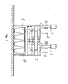
- Der erfindungsgemäße Heizautomat nach Figur 4 + 5 unterscheidet sich von dem Heizautomaten nach Figuren 1 - 3 durch einen anders angeordneten und mit 11 bezeichneten Saugzugventilator, der die Funktion des Saugzuges 2 und Gebläses 3 nach Figur 1 - 3 hat. Die in dem Heizautomaten entstehenden Gase werden über hintere, hohl ausgebildete Seitenwangen 20 abgezogen. Die Seitenwangen 20 sind in Figur 5 als vor der Schnittlinie A-B liegend mit Strichpunktlinien dargestellt. Die Gase treten oben bei 21 in die Seitenwangen und werden unten vom Saugzugventilator 11 abgezogen. Darüber hinaus ist im Bereich der oberen Umlenkzunge 12 der Retorte ein Düsenrohr 13 angeordnet. Das Düsenrohr 13 ist mit der Umlenkzunge 12 der Retorte verschweißt und besitzt eine Anzahl zum Feuerraum versetzt angeordneter Düsen. Das Düsenrohr 13 wird bei wassergekühlt ausgelegter Umlenkzunge 12 durch das Wasser der Umlenkzunge 12 mitgekühlt. Das gewährleistet eine angemessene Lebensdauer.
- Die während der Stillstandszeit des Saugzugventilators 11 entstehenden Schwelgase werden mittels eines 2. Saugzugventilators 14 im Ansaugstutzen des Saugzugventilators 11 über eine Leitung 15 abgesaugt. Zugleich wird Verbrennungsluft über einen Ansaugstutzen 16 angesaugt. Durch Einmünden der Leitung 15 und des Ansaugstutzens 16 in eine gemeinsame Zuführungsleitung 17 zum Saugzugventilator 14 entsteht eine Vermischung der angesaugten Verbrennungsluft mit dem abgesaugten Schwelgas. Dieses Gemisch wird von dem Saugzugventilator 14 in das Düsenrohr 13 gedrückt und tritt aus dessen Düsen in den Feuerungsraum ein, so daß die Schwelgase nachverbrannt werden können.
- Die Absaugleitung 15 und der Ansaugstutzen 16 lassen sich durch Klappen steuern, die über eine in Figur 4 schematisch dargestellte Mechanik gemeinsam betätigt werden können.
- Für den erfindungsgemäßen Heizautomaten nach Figur 4 + 5 ergibt sich folgendes Schaltbild:
- Nach Erreichen einer am Thermostaten eingestellten Vorlauftemperatur wird der Saugzugventilator 11 abgeschaltet. Zugleich schaltet sich der Saugzugventilator 14 ein, und ein Stellmotor öffnet die Regelklappen in der Absaugleitung 15 und im Verbrennungsluftansaugstutzen 16.
- Nach Abfallen der Temperatur wird über den Thermostaten der Saugzugventilator 11 wieder eingeschaltet und werden zugleich der Saugzugventilator 14 ausgeschaltet und Üter den Stellmotor beide Regelklappen wieder geschlossen.
- Die sich ergebenden Emissionswerte sind in Figur 6 dargestellt. Der Darstellung liegt eine Messung nach DIN 18 890 Blatt 10 zugrunde. Die Darstellung enthält ebenfalls die Saugzeiten des Saugzugventilators für Primärluft und die des 2. Ventilators für Sekundärluft. Die Verbesserung der Feststoffemission wird hierdurch treffend dargestellt. Die Laufzeit des Sekundärluftventilators beginnt bei der Stillstandszeit des Primärluftventilators. Die Schaltzeiten sind leistungsabhängig und sind bei Gasflammkohle und Brechkoks 4 etwa gleich. Bei Verfeuerung von Brechkoks 4 ist der Sekundärluftventilator ausgeschaltet.
Claims (9)
Priority Applications (1)
| Application Number | Priority Date | Filing Date | Title |
|---|---|---|---|
| AT82100088T ATE13778T1 (de) | 1981-01-28 | 1982-01-08 | Heizautomat. |
Applications Claiming Priority (4)
| Application Number | Priority Date | Filing Date | Title |
|---|---|---|---|
| DE19818102023 DE8102023U1 (de) | 1981-01-28 | 1981-01-28 | "heizautomat" |
| DE8102023U | 1981-01-28 | ||
| DE3128330 | 1981-07-17 | ||
| DE3128330 | 1981-07-17 |
Publications (3)
| Publication Number | Publication Date |
|---|---|
| EP0057347A2 true EP0057347A2 (de) | 1982-08-11 |
| EP0057347A3 EP0057347A3 (en) | 1982-09-22 |
| EP0057347B1 EP0057347B1 (de) | 1985-06-12 |
Family
ID=25794671
Family Applications (1)
| Application Number | Title | Priority Date | Filing Date |
|---|---|---|---|
| EP82100088A Expired EP0057347B1 (de) | 1981-01-28 | 1982-01-08 | Heizautomat |
Country Status (3)
| Country | Link |
|---|---|
| EP (1) | EP0057347B1 (de) |
| DE (1) | DE3264092D1 (de) |
| DK (1) | DK156147C (de) |
Family Cites Families (3)
| Publication number | Priority date | Publication date | Assignee | Title |
|---|---|---|---|---|
| DE575133C (de) * | 1931-01-23 | 1933-04-24 | Eugen Haber | Einrichtung zur Rueckfuehrung eines Teiles der Rauchgase zwecks ihrer Beimischung zur Verbrennungsluft bei mit einem Saugzugventilator versehenen Anlagen |
| CH215623A (de) * | 1941-04-01 | 1941-07-15 | Weber Heinrich | Apparat zur Brennstoffeinsparung bei Öfen, Warmwasser- und Dampfkesseln. |
| GB1472591A (en) * | 1975-01-09 | 1977-05-04 | Coal Ind | Solid fuel fired heaters |
-
1982
- 1982-01-08 DE DE8282100088T patent/DE3264092D1/de not_active Expired
- 1982-01-08 EP EP82100088A patent/EP0057347B1/de not_active Expired
- 1982-01-25 DK DK031382A patent/DK156147C/da not_active IP Right Cessation
Also Published As
| Publication number | Publication date |
|---|---|
| DK31382A (da) | 1982-07-29 |
| EP0057347A3 (en) | 1982-09-22 |
| DK156147C (da) | 1989-11-20 |
| DK156147B (da) | 1989-06-26 |
| EP0057347B1 (de) | 1985-06-12 |
| DE3264092D1 (en) | 1985-07-18 |
Similar Documents
| Publication | Publication Date | Title |
|---|---|---|
| DE3718022C1 (en) | Boiler burning solid matter | |
| WO1985004236A1 (fr) | Chaudiere de chauffage a gazeification de matiere solide | |
| DE3787027T2 (de) | Ofen. | |
| EP0057347B1 (de) | Heizautomat | |
| DE3324411C2 (de) | ||
| DE3705406A1 (de) | Feststoffvergasungsheizkessel | |
| DE1451505A1 (de) | Verfahren zur Verbrennung von Hausmuell und/oder industriellem Muell sowie mechanische Rostfeuerung zur Durchfuehrung dieses Verfahrens | |
| DE3150188A1 (de) | "heizautomat" | |
| DE283434C (de) | ||
| DE3020798C2 (de) | Verfahren zur Energiegewinnung aus Stroh | |
| DE636761C (de) | Muellverbrennungsofen | |
| AT528101B1 (de) | Heizvorrichtung, insbesondere Holzvergaserkessel, und Anordnung der Heizvorrichtung | |
| DE1019788B (de) | Zweitluftzufuehrung mit Rauchgas-Ruecksauge-Geblaese fuer eine UEberschubfeuerung | |
| DE3524962A1 (de) | Verbrennungsofen | |
| DE830101C (de) | Heizofen. | |
| DE4009316A1 (de) | Heizvorrichtung fuer feste brennstoffe | |
| DE398884C (de) | Brenner zur Verbrennung von Brennstoffen | |
| AT397139B (de) | Feuerung für die verbrennung fester brennstoffe | |
| DE702612C (de) | Muehlenfeuerung mit den Muehlen vorgeschalteten Vortrockenrosten | |
| DE3809429A1 (de) | Brennersystem zur verbrennung von festen brennstoffen in gasfoermigem zustand | |
| DE284163C (de) | ||
| DE972396C (de) | Schachtfeuerung, vorzugsweise fuer Grobkoks | |
| DE19709173C1 (de) | Ofen zur Feuerung von festem Brennstoff | |
| DE309726C (de) | ||
| AT258445B (de) | Verfahren zum Herabsetzen der Verbrennungstemperatur in einer Feuerungsanlage zum Verbrennen von Abfallstoffen und Feuerungsanlage zur Ausübung des Verfahrens |
Legal Events
| Date | Code | Title | Description |
|---|---|---|---|
| PUAI | Public reference made under article 153(3) epc to a published international application that has entered the european phase |
Free format text: ORIGINAL CODE: 0009012 |
|
| PUAL | Search report despatched |
Free format text: ORIGINAL CODE: 0009013 |
|
| AK | Designated contracting states |
Designated state(s): AT BE CH DE FR GB IT LU NL SE |
|
| AK | Designated contracting states |
Designated state(s): AT BE CH DE FR GB IT LU NL SE |
|
| 17P | Request for examination filed |
Effective date: 19820813 |
|
| ITF | It: translation for a ep patent filed | ||
| GRAA | (expected) grant |
Free format text: ORIGINAL CODE: 0009210 |
|
| AK | Designated contracting states |
Designated state(s): AT BE CH DE FR GB IT LI LU NL SE |
|
| REF | Corresponds to: |
Ref document number: 13778 Country of ref document: AT Date of ref document: 19850615 Kind code of ref document: T |
|
| REF | Corresponds to: |
Ref document number: 3264092 Country of ref document: DE Date of ref document: 19850718 |
|
| ET | Fr: translation filed | ||
| PG25 | Lapsed in a contracting state [announced via postgrant information from national office to epo] |
Ref country code: LU Free format text: LAPSE BECAUSE OF NON-PAYMENT OF DUE FEES Effective date: 19860131 |
|
| PLBE | No opposition filed within time limit |
Free format text: ORIGINAL CODE: 0009261 |
|
| STAA | Information on the status of an ep patent application or granted ep patent |
Free format text: STATUS: NO OPPOSITION FILED WITHIN TIME LIMIT |
|
| 26N | No opposition filed | ||
| PGFP | Annual fee paid to national office [announced via postgrant information from national office to epo] |
Ref country code: AT Payment date: 19881115 Year of fee payment: 8 |
|
| PGFP | Annual fee paid to national office [announced via postgrant information from national office to epo] |
Ref country code: CH Payment date: 19881125 Year of fee payment: 8 |
|
| PGFP | Annual fee paid to national office [announced via postgrant information from national office to epo] |
Ref country code: GB Payment date: 19890108 Year of fee payment: 8 |
|
| PGFP | Annual fee paid to national office [announced via postgrant information from national office to epo] |
Ref country code: FR Payment date: 19890118 Year of fee payment: 8 |
|
| PGFP | Annual fee paid to national office [announced via postgrant information from national office to epo] |
Ref country code: DE Payment date: 19890121 Year of fee payment: 8 |
|
| PGFP | Annual fee paid to national office [announced via postgrant information from national office to epo] |
Ref country code: SE Payment date: 19890131 Year of fee payment: 8 Ref country code: NL Payment date: 19890131 Year of fee payment: 10 |
|
| PGFP | Annual fee paid to national office [announced via postgrant information from national office to epo] |
Ref country code: BE Payment date: 19890206 Year of fee payment: 8 |
|
| PG25 | Lapsed in a contracting state [announced via postgrant information from national office to epo] |
Ref country code: DE Effective date: 19890509 |
|
| PG25 | Lapsed in a contracting state [announced via postgrant information from national office to epo] |
Ref country code: GB Effective date: 19900108 Ref country code: AT Effective date: 19900108 |
|
| PG25 | Lapsed in a contracting state [announced via postgrant information from national office to epo] |
Ref country code: SE Effective date: 19900109 |
|
| PG25 | Lapsed in a contracting state [announced via postgrant information from national office to epo] |
Ref country code: LI Effective date: 19900131 Ref country code: CH Effective date: 19900131 Ref country code: BE Effective date: 19900131 |
|
| BERE | Be: lapsed |
Owner name: RUHRKOHLE A.G. Effective date: 19900131 |
|
| PG25 | Lapsed in a contracting state [announced via postgrant information from national office to epo] |
Ref country code: NL Effective date: 19900801 |
|
| GBPC | Gb: european patent ceased through non-payment of renewal fee | ||
| NLV4 | Nl: lapsed or anulled due to non-payment of the annual fee | ||
| PG25 | Lapsed in a contracting state [announced via postgrant information from national office to epo] |
Ref country code: FR Effective date: 19900928 |
|
| REG | Reference to a national code |
Ref country code: CH Ref legal event code: PL |
|
| REG | Reference to a national code |
Ref country code: FR Ref legal event code: ST |
|
| EUG | Se: european patent has lapsed |
Ref document number: 82100088.2 Effective date: 19901106 |