EP0057407A2 - Soupape magnétique d'injection de carburant - Google Patents
Soupape magnétique d'injection de carburant Download PDFInfo
- Publication number
- EP0057407A2 EP0057407A2 EP82100515A EP82100515A EP0057407A2 EP 0057407 A2 EP0057407 A2 EP 0057407A2 EP 82100515 A EP82100515 A EP 82100515A EP 82100515 A EP82100515 A EP 82100515A EP 0057407 A2 EP0057407 A2 EP 0057407A2
- Authority
- EP
- European Patent Office
- Prior art keywords
- valve
- fuel
- housing
- globe
- fuel injection
- Prior art date
- Legal status (The legal status is an assumption and is not a legal conclusion. Google has not performed a legal analysis and makes no representation as to the accuracy of the status listed.)
- Granted
Links
Images

Classifications
-
- F—MECHANICAL ENGINEERING; LIGHTING; HEATING; WEAPONS; BLASTING
- F02—COMBUSTION ENGINES; HOT-GAS OR COMBUSTION-PRODUCT ENGINE PLANTS
- F02M—SUPPLYING COMBUSTION ENGINES IN GENERAL WITH COMBUSTIBLE MIXTURES OR CONSTITUENTS THEREOF
- F02M51/00—Fuel-injection apparatus characterised by being operated electrically
-
- F—MECHANICAL ENGINEERING; LIGHTING; HEATING; WEAPONS; BLASTING
- F02—COMBUSTION ENGINES; HOT-GAS OR COMBUSTION-PRODUCT ENGINE PLANTS
- F02M—SUPPLYING COMBUSTION ENGINES IN GENERAL WITH COMBUSTIBLE MIXTURES OR CONSTITUENTS THEREOF
- F02M61/00—Fuel-injectors not provided for in groups F02M39/00 - F02M57/00 or F02M67/00
- F02M61/16—Details not provided for in, or of interest apart from, the apparatus of groups F02M61/02 - F02M61/14
- F02M61/162—Means to impart a whirling motion to fuel upstream or near discharging orifices
- F02M61/163—Means being injection-valves with helically or spirally shaped grooves
-
- F—MECHANICAL ENGINEERING; LIGHTING; HEATING; WEAPONS; BLASTING
- F02—COMBUSTION ENGINES; HOT-GAS OR COMBUSTION-PRODUCT ENGINE PLANTS
- F02M—SUPPLYING COMBUSTION ENGINES IN GENERAL WITH COMBUSTIBLE MIXTURES OR CONSTITUENTS THEREOF
- F02M51/00—Fuel-injection apparatus characterised by being operated electrically
- F02M51/06—Injectors peculiar thereto with means directly operating the valve needle
- F02M51/061—Injectors peculiar thereto with means directly operating the valve needle using electromagnetic operating means
- F02M51/0625—Injectors peculiar thereto with means directly operating the valve needle using electromagnetic operating means characterised by arrangement of mobile armatures
- F02M51/0664—Injectors peculiar thereto with means directly operating the valve needle using electromagnetic operating means characterised by arrangement of mobile armatures having a cylindrically or partly cylindrically shaped armature, e.g. entering the winding; having a plate-shaped or undulated armature entering the winding
- F02M51/0671—Injectors peculiar thereto with means directly operating the valve needle using electromagnetic operating means characterised by arrangement of mobile armatures having a cylindrically or partly cylindrically shaped armature, e.g. entering the winding; having a plate-shaped or undulated armature entering the winding the armature having an elongated valve body attached thereto
- F02M51/0675—Injectors peculiar thereto with means directly operating the valve needle using electromagnetic operating means characterised by arrangement of mobile armatures having a cylindrically or partly cylindrically shaped armature, e.g. entering the winding; having a plate-shaped or undulated armature entering the winding the armature having an elongated valve body attached thereto the valve body having cylindrical guiding or metering portions, e.g. with fuel passages
-
- F—MECHANICAL ENGINEERING; LIGHTING; HEATING; WEAPONS; BLASTING
- F02—COMBUSTION ENGINES; HOT-GAS OR COMBUSTION-PRODUCT ENGINE PLANTS
- F02M—SUPPLYING COMBUSTION ENGINES IN GENERAL WITH COMBUSTIBLE MIXTURES OR CONSTITUENTS THEREOF
- F02M51/00—Fuel-injection apparatus characterised by being operated electrically
- F02M51/06—Injectors peculiar thereto with means directly operating the valve needle
- F02M51/08—Injectors peculiar thereto with means directly operating the valve needle specially for low-pressure fuel-injection
-
- F—MECHANICAL ENGINEERING; LIGHTING; HEATING; WEAPONS; BLASTING
- F02—COMBUSTION ENGINES; HOT-GAS OR COMBUSTION-PRODUCT ENGINE PLANTS
- F02M—SUPPLYING COMBUSTION ENGINES IN GENERAL WITH COMBUSTIBLE MIXTURES OR CONSTITUENTS THEREOF
- F02M61/00—Fuel-injectors not provided for in groups F02M39/00 - F02M57/00 or F02M67/00
- F02M61/16—Details not provided for in, or of interest apart from, the apparatus of groups F02M61/02 - F02M61/14
- F02M61/162—Means to impart a whirling motion to fuel upstream or near discharging orifices
-
- F—MECHANICAL ENGINEERING; LIGHTING; HEATING; WEAPONS; BLASTING
- F02—COMBUSTION ENGINES; HOT-GAS OR COMBUSTION-PRODUCT ENGINE PLANTS
- F02M—SUPPLYING COMBUSTION ENGINES IN GENERAL WITH COMBUSTIBLE MIXTURES OR CONSTITUENTS THEREOF
- F02M69/00—Low-pressure fuel-injection apparatus ; Apparatus with both continuous and intermittent injection; Apparatus injecting different types of fuel
- F02M69/04—Injectors peculiar thereto
- F02M69/047—Injectors peculiar thereto injectors with air chambers, e.g. communicating with atmosphere for aerating the nozzles
-
- F—MECHANICAL ENGINEERING; LIGHTING; HEATING; WEAPONS; BLASTING
- F02—COMBUSTION ENGINES; HOT-GAS OR COMBUSTION-PRODUCT ENGINE PLANTS
- F02M—SUPPLYING COMBUSTION ENGINES IN GENERAL WITH COMBUSTIBLE MIXTURES OR CONSTITUENTS THEREOF
- F02M69/00—Low-pressure fuel-injection apparatus ; Apparatus with both continuous and intermittent injection; Apparatus injecting different types of fuel
- F02M69/08—Low-pressure fuel-injection apparatus ; Apparatus with both continuous and intermittent injection; Apparatus injecting different types of fuel characterised by the fuel being carried by compressed air into main stream of combustion-air
-
- F—MECHANICAL ENGINEERING; LIGHTING; HEATING; WEAPONS; BLASTING
- F02—COMBUSTION ENGINES; HOT-GAS OR COMBUSTION-PRODUCT ENGINE PLANTS
- F02M—SUPPLYING COMBUSTION ENGINES IN GENERAL WITH COMBUSTIBLE MIXTURES OR CONSTITUENTS THEREOF
- F02M2200/00—Details of fuel-injection apparatus, not otherwise provided for
- F02M2200/50—Arrangements of springs for valves used in fuel injectors or fuel injection pumps
- F02M2200/507—Adjusting spring tension by screwing spring seats
-
- Y—GENERAL TAGGING OF NEW TECHNOLOGICAL DEVELOPMENTS; GENERAL TAGGING OF CROSS-SECTIONAL TECHNOLOGIES SPANNING OVER SEVERAL SECTIONS OF THE IPC; TECHNICAL SUBJECTS COVERED BY FORMER USPC CROSS-REFERENCE ART COLLECTIONS [XRACs] AND DIGESTS
- Y10—TECHNICAL SUBJECTS COVERED BY FORMER USPC
- Y10S—TECHNICAL SUBJECTS COVERED BY FORMER USPC CROSS-REFERENCE ART COLLECTIONS [XRACs] AND DIGESTS
- Y10S239/00—Fluid sprinkling, spraying, and diffusing
- Y10S239/90—Electromagnetically actuated fuel injector having ball and seat type valve
Definitions
- This invention relates to a magnetic fuel injection valve for internal combustion engines and more particularly to a fuel injection valve which employs a globe valve to improve the atomization of fuel when injecting fuel in pulsation.
- the conventional magnetic fuel injection valve using a globe valve as the valve disk has the advantage over the pintle type that there is a greater allowance for the inclination of the valve disk relative to the valve seat.
- the conventional fuel injection valve has the drawback that it is difficult to work on the globe valve to increase the diffusing angle of fuel spray with the resultant poor fuel atomization.
- a fuel injection valve in which the fuel is supplied at high speed from the inlet orifice - which is cut through the valve housing from the external surface to the inner surface in the direction tangent to the outer surface of the globe valve - into the votex chamber enclosed by the inner surface of the valve housing, the outer surface of the globe valve and the valve seat, so that the supplied fuel swirls in the vortex chamber to increase the diffusing angle of the fuel spray injected out of the outlet orifice .
- the apparent flow coefficient at the valve seat becomes small, so that it is necessary to increase the valve stroke to secure the fuel passage area at the valve seat.
- the object of this invention is to provide a magnetic fuel injection valve which overcomes the conventional drawbacks mentioned above and which improves the diffusing angle of the fuel spray when the valve begins to open, i.e., when the fuel begins to be injected, and performs an excellent control on the fuel injection in the small pulse width range or the small fuel flow range.
- This invention is characterized in that the fuel from the fuel pressure shource is supplied, without any swirling motion, to the immediate upstream of the valve seat of the globe valve, that a means is provided immediately downstream of the valve seat to swirl the fuel in the direction perpendicular to the direction of injection, and that a fuel metering orifice is provided immediately downstream of the above means .
- the globe valve 10 is reciprocated in the valve housing 12 to open and close the fuel passage 16 at the valve seat 14.
- the globe valve 10 is connected integrally with the plunger 20 through the rod 18, these three members constituting a moving unit 22.
- the moving unit 22 is contained in the valve housing 12 and the yoke 26 so that it is slidable in. the axial direction of the valve housing 12 and the yoke 26 and it is guided by the outer surface of the globe valve 10 and the collar 24 of the rod 18.
- the collar 24 abouts against the stopper 28 provided between the valve housing 12 and the yoke 26 and determines the stroke of the globe valve 10.
- the valve housing 12 and the stopper 28 are fixed inside the yoke 26. At the center of the yoke 26 is provided a core 30.
- a coil 32 is installed between the yoke 26 and the core 30.
- One end of the core 30 opposes one end of the plunger 20 with an air gap between them.
- the yoke 26, core 30 and plunger 20 are formed of soft magnetic material and constitute the magnetic circuit.
- a spring 34 which urges the plunger 20 toward the valve seat 14.
- a fuel inlet 36 opens at one end between the valve seat 14 and the inner surface of the valve housing 12 on which the globe valve 10 slides. The other end of the fuel inlet 36 opens to the external surface of the valve housing 12.
- the fuel inlet 36 runs almost in the direction of the central axis of the globe valve 10 so as to prevent the formation of vortex flow around the globe valve 10.
- a spiral member 40 which is a rod with a spiral fuel groove 38 to swirl the fuel along the groove.
- An outlet orifice 42 for fuel metering is formed immediately downstream of and as close as possible to the spiral member 40.
- valve seat 14 is not provided between the spiral member 4o to swirl the fuel, the space between the spiral member 4o and the outlet orifice 42 can be made small in which the fuel can stay stagnant. This reduces the amount of fuel that is injected from the outlet orifice 42 without being swirled when the fuel begins to be injected, thus improving the control performance in the range of small fuel flow. Further, since the fuel is not metered by the inlet orifice, the inlet orifice does not require high precision machining.
- the fuel injection valve of this invention has the advantages as follows. Since the fuel is fed from the immediate upstream of the valve seat, there are only the valve seat 14 and the spiral member 4o that the fuel must flow past to reach the fuel metering outlet orifice 42, so that, at the start of fuel injection, the fuel pressure reduction just before the outlet orifice 42 can be minimized to ensure sufficient flow speed of fuel passing through the spiral member 4 0 . This eliminates the drawback of the conventional fuel injection valve that when the fuel begins to be injected, the diffusion angle of the spray fuel is small.
- the diffusing angle of the sprayed fuel at the start of injection can be increased, thus improving the control performance in the range of small control pulse width or small fuel injection as well as the quality of atomized fuel.
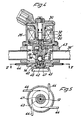
- the fuel injection valve is essential the same like in Figure 1. Additional the valve housing 12 is surrounded by a housing 43, having fuel inlets 36'. This housing 43 is arranged by means of a O-ring- sealing-device (47) on the downstream-end of the valve housing 12 and is provided with tangential bores 44 for introducing assisting air. These bores 44 are joining with a conical space. 45 in order to blow the assisting air towards the axis of the outlet orifice 42. The swirl in this space 45 has a direction opposite to the direction of the grooves 33 of the spiral member 40 and in such a way the atomization of the fuel is enhanced.
- Fig. 5 shows a cross section V-V of Figure 4.
- the bores 44 produce a swirl (in the drawing clockwise) which is opposite to the direction of the spiral grooves in the spiral member 4 0 .
Landscapes
- Engineering & Computer Science (AREA)
- Chemical & Material Sciences (AREA)
- Combustion & Propulsion (AREA)
- Mechanical Engineering (AREA)
- General Engineering & Computer Science (AREA)
- Physics & Mathematics (AREA)
- Electromagnetism (AREA)
- Fuel-Injection Apparatus (AREA)
Applications Claiming Priority (2)
| Application Number | Priority Date | Filing Date | Title |
|---|---|---|---|
| JP13486/81 | 1981-01-30 | ||
| JP56013486A JPS57126554A (en) | 1981-01-30 | 1981-01-30 | Electro magnetic fuel jet valve |
Publications (3)
| Publication Number | Publication Date |
|---|---|
| EP0057407A2 true EP0057407A2 (fr) | 1982-08-11 |
| EP0057407A3 EP0057407A3 (en) | 1982-08-25 |
| EP0057407B1 EP0057407B1 (fr) | 1987-05-20 |
Family
ID=11834440
Family Applications (1)
| Application Number | Title | Priority Date | Filing Date |
|---|---|---|---|
| EP82100515A Expired EP0057407B1 (fr) | 1981-01-30 | 1982-01-26 | Soupape magnétique d'injection de carburant |
Country Status (5)
| Country | Link |
|---|---|
| US (1) | US4520962A (fr) |
| EP (1) | EP0057407B1 (fr) |
| JP (1) | JPS57126554A (fr) |
| KR (1) | KR830009364A (fr) |
| DE (1) | DE3276384D1 (fr) |
Cited By (8)
| Publication number | Priority date | Publication date | Assignee | Title |
|---|---|---|---|---|
| FR2513321A1 (fr) * | 1981-05-30 | 1983-03-25 | Bosch Gmbh Robert | Soupape d'injection de carburant pour moteurs a combustion interne |
| GB2129492A (en) * | 1982-11-03 | 1984-05-16 | Bosch Gmbh Robert | I c engine fuel injection valve |
| DE3531153A1 (de) * | 1985-06-14 | 1986-12-18 | Pierburg Gmbh & Co Kg, 4040 Neuss | Elektromagnetisches, intermittierendes einspritzventil |
| EP0360040A3 (fr) * | 1988-08-29 | 1990-07-18 | Japan Electronic Control Systems Co., Ltd. | Système d'alimentation en air d'injection pour moteurs à combustion interne |
| EP0476298A1 (fr) * | 1990-09-21 | 1992-03-25 | Robert Bosch Gmbh | Soupape d'injection pour l'alimentation d'un moteur à combustion interne avec un mélange de carburant et de gas |
| US5516047A (en) * | 1993-08-24 | 1996-05-14 | Robert Bosch Gmbh | Electromagnetically actuated fuel injection valve |
| WO1998011341A1 (fr) | 1996-09-12 | 1998-03-19 | Robert Bosch Gmbh | Soupape, en particulier soupape d'injection de carburant |
| WO1998042979A1 (fr) * | 1997-03-22 | 1998-10-01 | Robert Bosch Gmbh | Soupape d'injection de carburant |
Families Citing this family (56)
| Publication number | Priority date | Publication date | Assignee | Title |
|---|---|---|---|---|
| US4981266A (en) * | 1981-05-30 | 1991-01-01 | Robert Bosch Gmbh | Injection valve |
| JPS5956371U (ja) * | 1982-10-07 | 1984-04-12 | 愛三工業株式会社 | 電磁燃料噴射器 |
| JPS6035169A (ja) * | 1983-08-08 | 1985-02-22 | Hitachi Ltd | 燃料噴射弁 |
| IT1213039B (it) * | 1986-02-18 | 1989-12-07 | Spica Spa | Combustione interna. iniettore ad azionamento elettromagnetico per motori a |
| DE3723698C2 (de) * | 1987-07-17 | 1995-04-27 | Bosch Gmbh Robert | Kraftstoffeinspritzventil sowie Verfahren zu dessen Einstellung |
| US5199648A (en) * | 1991-03-20 | 1993-04-06 | Zexel Corporation | Fuel injection valve |
| DE4234450A1 (de) * | 1992-10-13 | 1994-04-14 | Swoboda Peter | Elektromagnetisch betätigtes Einspritzventil |
| US5271565A (en) * | 1992-12-18 | 1993-12-21 | Chrysler Corporation | Fuel injector with valve bounce inhibiting means |
| US5289627A (en) * | 1992-12-18 | 1994-03-01 | Chrysler Corporation | Fuel injector assembly and calibration method |
| US5288025A (en) * | 1992-12-18 | 1994-02-22 | Chrysler Corporation | Fuel injector with a hydraulically cushioned valve |
| DE4408875A1 (de) * | 1994-03-16 | 1995-09-21 | Bosch Gmbh Robert | Brennstoffeinspritzventil |
| DE19626576A1 (de) * | 1996-07-02 | 1998-01-08 | Bosch Gmbh Robert | Brennstoffeinspritzventil |
| US5875747A (en) * | 1997-03-26 | 1999-03-02 | Lamp; Justin | Internal combustion engine |
| US6250284B1 (en) | 1997-03-26 | 2001-06-26 | Justin Lamp | Engine with fuel delivery system |
| US6047907A (en) | 1997-12-23 | 2000-04-11 | Siemens Automotive Corporation | Ball valve fuel injector |
| US6676044B2 (en) | 2000-04-07 | 2004-01-13 | Siemens Automotive Corporation | Modular fuel injector and method of assembling the modular fuel injector |
| US6481646B1 (en) | 2000-09-18 | 2002-11-19 | Siemens Automotive Corporation | Solenoid actuated fuel injector |
| DE10050055A1 (de) | 2000-10-10 | 2002-04-18 | Bosch Gmbh Robert | Brennstoffeinspritzventil |
| US6695232B2 (en) | 2000-12-29 | 2004-02-24 | Siemens Automotive Corporation | Modular fuel injector having interchangeable armature assemblies and having a lift set sleeve |
| US6811091B2 (en) | 2000-12-29 | 2004-11-02 | Siemens Automotive Corporation | Modular fuel injector having an integral filter and dynamic adjustment assembly |
| US6533188B1 (en) | 2000-12-29 | 2003-03-18 | Siemens Automotive Corporation | Modular fuel injector having a snap-on orifice disk retainer and having an integral filter and dynamic adjustment assembly |
| US6523756B2 (en) | 2000-12-29 | 2003-02-25 | Siemens Automotive Corporation | Modular fuel injector having a low mass, high efficiency electromagnetic actuator and having a lift set sleeve |
| US6550690B2 (en) | 2000-12-29 | 2003-04-22 | Siemens Automotive Corporation | Modular fuel injector having interchangeable armature assemblies and having an integral filter and dynamic adjustment assembly |
| US6565019B2 (en) | 2000-12-29 | 2003-05-20 | Seimens Automotive Corporation | Modular fuel injector having a snap-on orifice disk retainer and having an integral filter and O-ring retainer assembly |
| US6607143B2 (en) | 2000-12-29 | 2003-08-19 | Siemens Automotive Corporation | Modular fuel injector having a surface treatment on an impact surface of an electromagnetic actuator and having a lift set sleeve |
| US6502770B2 (en) | 2000-12-29 | 2003-01-07 | Siemens Automotive Corporation | Modular fuel injector having a snap-on orifice disk retainer and having a terminal connector interconnecting an electromagnetic actuator with an electrical terminal |
| US6536681B2 (en) | 2000-12-29 | 2003-03-25 | Siemens Automotive Corporation | Modular fuel injector having a surface treatment on an impact surface of an electromagnetic actuator and having an integral filter and O-ring retainer assembly |
| US6511003B2 (en) | 2000-12-29 | 2003-01-28 | Siemens Automotive Corporation | Modular fuel injector having an integral or interchangeable inlet tube and having a terminal connector interconnecting an electromagnetic actuator with an electrical terminal |
| US6655609B2 (en) | 2000-12-29 | 2003-12-02 | Siemens Automotive Corporation | Modular fuel injector having a low mass, high efficiency electromagnetic actuator and having an integral filter and o-ring retainer assembly |
| US6698664B2 (en) | 2000-12-29 | 2004-03-02 | Siemens Automotive Corporation | Modular fuel injector having an integral or interchangeable inlet tube and having an integral filter and dynamic adjustment assembly |
| US6523760B2 (en) | 2000-12-29 | 2003-02-25 | Siemens Automotive Corporation | Modular fuel injector having interchangeable armature assemblies and having a terminal connector interconnecting an electromagnetic actuator with an electrical terminal |
| US6568609B2 (en) | 2000-12-29 | 2003-05-27 | Siemens Automotive Corporation | Modular fuel injector having an integral or interchangeable inlet tube and having an integral filter and o-ring retainer assembly |
| US6499668B2 (en) | 2000-12-29 | 2002-12-31 | Siemens Automotive Corporation | Modular fuel injector having a surface treatment on an impact surface of an electromagnetic actuator and having a terminal connector interconnecting an electromagnetic actuator with an electrical terminal |
| US6769636B2 (en) | 2000-12-29 | 2004-08-03 | Siemens Automotive Corporation | Modular fuel injector having interchangeable armature assemblies and having an integral filter and O-ring retainer assembly |
| US6708906B2 (en) * | 2000-12-29 | 2004-03-23 | Siemens Automotive Corporation | Modular fuel injector having a surface treatment on an impact surface of an electromagnetic actuator and having an integral filter and dynamic adjustment assembly |
| US6523761B2 (en) | 2000-12-29 | 2003-02-25 | Siemens Automotive Corporation | Modular fuel injector having an integral or interchangeable inlet tube and having a lift set sleeve |
| US6543707B2 (en) | 2000-12-29 | 2003-04-08 | Siemens Automotive Corporation | Modular fuel injector having a lift set sleeve |
| US6508417B2 (en) * | 2000-12-29 | 2003-01-21 | Siemens Automotive Corporation | Modular fuel injector having a snap-on orifice disk retainer and having a lift set sleeve |
| US6547154B2 (en) | 2000-12-29 | 2003-04-15 | Siemens Automotive Corporation | Modular fuel injector having a terminal connector interconnecting an electromagnetic actuator with a pre-bent electrical terminal |
| US6520421B2 (en) | 2000-12-29 | 2003-02-18 | Siemens Automotive Corporation | Modular fuel injector having an integral filter and o-ring retainer |
| US6499677B2 (en) | 2000-12-29 | 2002-12-31 | Siemens Automotive Corporation | Modular fuel injector having a low mass, high efficiency electromagnetic actuator and having an integral filter and dynamic adjustment assembly |
| US7093362B2 (en) | 2001-03-30 | 2006-08-22 | Siemens Vdo Automotive Corporation | Method of connecting components of a modular fuel injector |
| US6904668B2 (en) | 2001-03-30 | 2005-06-14 | Siemens Vdo Automotive Corp. | Method of manufacturing a modular fuel injector |
| US6687997B2 (en) | 2001-03-30 | 2004-02-10 | Siemens Automotive Corporation | Method of fabricating and testing a modular fuel injector |
| US6676043B2 (en) | 2001-03-30 | 2004-01-13 | Siemens Automotive Corporation | Methods of setting armature lift in a modular fuel injector |
| US7762476B2 (en) * | 2002-08-19 | 2010-07-27 | Illinois Tool Works Inc. | Spray gun with improved atomization |
| US6808122B2 (en) * | 2002-08-19 | 2004-10-26 | Illinois Tool Works, Inc. | Spray gun with improved pre-atomization fluid mixing and breakup |
| JP2004353661A (ja) * | 2003-05-01 | 2004-12-16 | Hitachi Ltd | 燃料噴射弁及びそれを備えた筒内噴射式内燃機関 |
| US7926733B2 (en) * | 2004-06-30 | 2011-04-19 | Illinois Tool Works Inc. | Fluid atomizing system and method |
| US7883026B2 (en) | 2004-06-30 | 2011-02-08 | Illinois Tool Works Inc. | Fluid atomizing system and method |
| US8684281B2 (en) * | 2006-03-24 | 2014-04-01 | Finishing Brands Holdings Inc. | Spray device having removable hard coated tip |
| US20080017734A1 (en) * | 2006-07-10 | 2008-01-24 | Micheli Paul R | System and method of uniform spray coating |
| US8225602B2 (en) * | 2009-06-11 | 2012-07-24 | Stanadyne Corporation | Integrated pump and injector for exhaust after treatment |
| US20100314470A1 (en) * | 2009-06-11 | 2010-12-16 | Stanadyne Corporation | Injector having swirl structure downstream of valve seat |
| JP5617892B2 (ja) * | 2012-10-12 | 2014-11-05 | トヨタ自動車株式会社 | 燃料噴射弁 |
| JP6401085B2 (ja) * | 2015-03-13 | 2018-10-03 | 日立オートモティブシステムズ株式会社 | 燃料噴射弁 |
Family Cites Families (13)
| Publication number | Priority date | Publication date | Assignee | Title |
|---|---|---|---|---|
| DE298770C (fr) * | ||||
| FR857891A (fr) * | 1939-07-15 | 1940-10-03 | Scintilla Sa | Injecteur de combustible pour moteurs à combustion interne |
| US2969784A (en) * | 1958-03-13 | 1961-01-31 | Borg Warner | Fuel injection mechanism |
| FR1358593A (fr) * | 1963-03-07 | 1964-04-17 | Tecalemit | Injecteur perfectionné pour l'alimentation des moteurs à combustion interne |
| FR2127146A5 (fr) * | 1971-02-25 | 1972-10-13 | Brev Etudes Sibe | |
| US3731880A (en) * | 1971-10-08 | 1973-05-08 | Gen Motors Corp | Ball valve electromagnetic fuel injector |
| FR2166734A5 (fr) * | 1972-01-06 | 1973-08-17 | Peugeot & Renault | |
| US3782639A (en) * | 1972-04-17 | 1974-01-01 | Ford Motor Co | Fuel injection apparatus |
| US4218021A (en) * | 1977-10-03 | 1980-08-19 | General Motors Corporation | Electromagnetic fuel injector |
| JPS5482528A (en) * | 1977-12-14 | 1979-06-30 | Toyota Motor Corp | Engine air-fuel-mixture supply system |
| US4186883A (en) * | 1978-05-08 | 1980-02-05 | Essex Group, Inc. | Electromagnetic fuel injection valve with swirl means |
| CA1132417A (fr) * | 1979-01-29 | 1982-09-28 | Gary L. Casey | Injecteur de carburant a commande electromagnetique |
| FR2492894B1 (fr) * | 1980-10-29 | 1985-06-07 | Renault | Injecteur a commande electromagnetique a bille |
-
1981
- 1981-01-30 JP JP56013486A patent/JPS57126554A/ja active Granted
-
1982
- 1982-01-26 DE DE8282100515T patent/DE3276384D1/de not_active Expired
- 1982-01-26 EP EP82100515A patent/EP0057407B1/fr not_active Expired
- 1982-01-29 KR KR1019810000376A patent/KR830009364A/ko not_active Withdrawn
- 1982-02-01 US US06/344,802 patent/US4520962A/en not_active Expired - Fee Related
Cited By (10)
| Publication number | Priority date | Publication date | Assignee | Title |
|---|---|---|---|---|
| FR2513321A1 (fr) * | 1981-05-30 | 1983-03-25 | Bosch Gmbh Robert | Soupape d'injection de carburant pour moteurs a combustion interne |
| GB2129492A (en) * | 1982-11-03 | 1984-05-16 | Bosch Gmbh Robert | I c engine fuel injection valve |
| DE3531153A1 (de) * | 1985-06-14 | 1986-12-18 | Pierburg Gmbh & Co Kg, 4040 Neuss | Elektromagnetisches, intermittierendes einspritzventil |
| EP0360040A3 (fr) * | 1988-08-29 | 1990-07-18 | Japan Electronic Control Systems Co., Ltd. | Système d'alimentation en air d'injection pour moteurs à combustion interne |
| US5024201A (en) * | 1988-08-29 | 1991-06-18 | Japan Electronic Control Systems Co., Ltd. | Assist air supply system for internal combustion engine |
| EP0476298A1 (fr) * | 1990-09-21 | 1992-03-25 | Robert Bosch Gmbh | Soupape d'injection pour l'alimentation d'un moteur à combustion interne avec un mélange de carburant et de gas |
| US5516047A (en) * | 1993-08-24 | 1996-05-14 | Robert Bosch Gmbh | Electromagnetically actuated fuel injection valve |
| WO1998011341A1 (fr) | 1996-09-12 | 1998-03-19 | Robert Bosch Gmbh | Soupape, en particulier soupape d'injection de carburant |
| US6089473A (en) * | 1996-09-12 | 2000-07-18 | Robert Bosch Gmbh | Valve, in particular a fuel injection valve |
| WO1998042979A1 (fr) * | 1997-03-22 | 1998-10-01 | Robert Bosch Gmbh | Soupape d'injection de carburant |
Also Published As
| Publication number | Publication date |
|---|---|
| DE3276384D1 (en) | 1987-06-25 |
| JPS619513B2 (fr) | 1986-03-24 |
| EP0057407A3 (en) | 1982-08-25 |
| KR830009364A (ko) | 1983-12-19 |
| EP0057407B1 (fr) | 1987-05-20 |
| JPS57126554A (en) | 1982-08-06 |
| US4520962A (en) | 1985-06-04 |
Similar Documents
| Publication | Publication Date | Title |
|---|---|---|
| EP0057407A2 (fr) | Soupape magnétique d'injection de carburant | |
| EP0753105B1 (fr) | Injecteurs de carburant dotes de nouveaux elements de disques a orifices multiples | |
| US4971254A (en) | Thin orifice swirl injector nozzle | |
| US4945877A (en) | Fuel injection valve | |
| US4365746A (en) | Swirl injection valve | |
| AU607871B2 (en) | Fuel injection valve | |
| CA1132417A (fr) | Injecteur de carburant a commande electromagnetique | |
| JP2000509462A (ja) | 燃料噴射器の渦発生器 | |
| US5044561A (en) | Injection valve for fuel injection systems | |
| KR100327077B1 (ko) | 연료및가스혼합물분사장치 | |
| US5170945A (en) | Fuel injector that swirls and throttles the flow to create to a toroidal fuel cloud | |
| US4634055A (en) | Injection valve with upstream internal metering | |
| US5012981A (en) | Injection valve | |
| US4487369A (en) | Electromagnetic fuel injector with improved discharge structure | |
| US5314122A (en) | Fuel injection valve | |
| US4753393A (en) | Electromagnetically actuatable fuel-injection valve | |
| US6851629B2 (en) | Fuel injection valve | |
| JPH05209572A (ja) | 電磁的に作動する噴射弁 | |
| US20040021010A1 (en) | Fuel injection valve | |
| KR100294369B1 (ko) | 내연기관용연료공급장치 | |
| JPS61272460A (ja) | 電磁式燃料噴射弁 | |
| JP2002507695A (ja) | 燃料噴射弁 | |
| KR880003529Y1 (ko) | 전자식 (電磁式) 연료분사밸브 | |
| GB2113300A (en) | Electromagnetic fuel injector with a spray determining discharge structure | |
| JP2555115B2 (ja) | 燃料噴射弁 |
Legal Events
| Date | Code | Title | Description |
|---|---|---|---|
| PUAI | Public reference made under article 153(3) epc to a published international application that has entered the european phase |
Free format text: ORIGINAL CODE: 0009012 |
|
| PUAL | Search report despatched |
Free format text: ORIGINAL CODE: 0009013 |
|
| AK | Designated contracting states |
Designated state(s): BE CH DE FR GB IT NL SE |
|
| AK | Designated contracting states |
Designated state(s): BE CH DE FR GB IT NL SE |
|
| 17P | Request for examination filed |
Effective date: 19830214 |
|
| GRAA | (expected) grant |
Free format text: ORIGINAL CODE: 0009210 |
|
| AK | Designated contracting states |
Kind code of ref document: B1 Designated state(s): BE CH DE FR GB IT LI NL SE |
|
| PG25 | Lapsed in a contracting state [announced via postgrant information from national office to epo] |
Ref country code: NL Effective date: 19870520 Ref country code: LI Effective date: 19870520 Ref country code: CH Effective date: 19870520 Ref country code: BE Effective date: 19870520 |
|
| REF | Corresponds to: |
Ref document number: 3276384 Country of ref document: DE Date of ref document: 19870625 |
|
| ET | Fr: translation filed | ||
| ITF | It: translation for a ep patent filed | ||
| REG | Reference to a national code |
Ref country code: CH Ref legal event code: PL |
|
| NLV1 | Nl: lapsed or annulled due to failure to fulfill the requirements of art. 29p and 29m of the patents act | ||
| PLBE | No opposition filed within time limit |
Free format text: ORIGINAL CODE: 0009261 |
|
| STAA | Information on the status of an ep patent application or granted ep patent |
Free format text: STATUS: NO OPPOSITION FILED WITHIN TIME LIMIT |
|
| 26N | No opposition filed | ||
| ITTA | It: last paid annual fee | ||
| PGFP | Annual fee paid to national office [announced via postgrant information from national office to epo] |
Ref country code: SE Payment date: 19911216 Year of fee payment: 11 |
|
| PGFP | Annual fee paid to national office [announced via postgrant information from national office to epo] |
Ref country code: FR Payment date: 19911218 Year of fee payment: 11 |
|
| PGFP | Annual fee paid to national office [announced via postgrant information from national office to epo] |
Ref country code: GB Payment date: 19920116 Year of fee payment: 11 |
|
| PG25 | Lapsed in a contracting state [announced via postgrant information from national office to epo] |
Ref country code: GB Effective date: 19930126 |
|
| PG25 | Lapsed in a contracting state [announced via postgrant information from national office to epo] |
Ref country code: SE Effective date: 19930127 |
|
| GBPC | Gb: european patent ceased through non-payment of renewal fee |
Effective date: 19930126 |
|
| PG25 | Lapsed in a contracting state [announced via postgrant information from national office to epo] |
Ref country code: FR Effective date: 19930930 |
|
| REG | Reference to a national code |
Ref country code: FR Ref legal event code: ST |
|
| PGFP | Annual fee paid to national office [announced via postgrant information from national office to epo] |
Ref country code: DE Payment date: 19940330 Year of fee payment: 13 |
|
| EUG | Se: european patent has lapsed |
Ref document number: 82100515.4 Effective date: 19930810 |
|
| PG25 | Lapsed in a contracting state [announced via postgrant information from national office to epo] |
Ref country code: DE Effective date: 19951003 |