EP0057521B1 - Bestimmung der plastischen Anisotropie in plattenförmigem Material - Google Patents
Bestimmung der plastischen Anisotropie in plattenförmigem Material Download PDFInfo
- Publication number
- EP0057521B1 EP0057521B1 EP82300205A EP82300205A EP0057521B1 EP 0057521 B1 EP0057521 B1 EP 0057521B1 EP 82300205 A EP82300205 A EP 82300205A EP 82300205 A EP82300205 A EP 82300205A EP 0057521 B1 EP0057521 B1 EP 0057521B1
- Authority
- EP
- European Patent Office
- Prior art keywords
- sheet
- thickness
- sheet material
- true
- measuring
- Prior art date
- Legal status (The legal status is an assumption and is not a legal conclusion. Google has not performed a legal analysis and makes no representation as to the accuracy of the status listed.)
- Expired
Links
- 239000000463 material Substances 0.000 title claims description 35
- 238000000034 method Methods 0.000 claims description 19
- 238000005259 measurement Methods 0.000 claims description 14
- 230000000644 propagated effect Effects 0.000 claims description 5
- 238000012545 processing Methods 0.000 claims description 4
- 230000001902 propagating effect Effects 0.000 claims description 4
- 229910000831 Steel Inorganic materials 0.000 claims description 2
- 239000010959 steel Substances 0.000 claims description 2
- 239000000523 sample Substances 0.000 description 9
- 238000012360 testing method Methods 0.000 description 3
- 239000000919 ceramic Substances 0.000 description 2
- 230000003287 optical effect Effects 0.000 description 2
- 238000009864 tensile test Methods 0.000 description 2
- 235000019687 Lamb Nutrition 0.000 description 1
- 229910001209 Low-carbon steel Inorganic materials 0.000 description 1
- 238000013459 approach Methods 0.000 description 1
- 150000001875 compounds Chemical class 0.000 description 1
- 238000010586 diagram Methods 0.000 description 1
- 230000006870 function Effects 0.000 description 1
- 239000002184 metal Substances 0.000 description 1
- 238000012986 modification Methods 0.000 description 1
- 230000004048 modification Effects 0.000 description 1
- 238000012544 monitoring process Methods 0.000 description 1
- 230000005855 radiation Effects 0.000 description 1
- 239000012925 reference material Substances 0.000 description 1
- 238000005096 rolling process Methods 0.000 description 1
- 238000002366 time-of-flight method Methods 0.000 description 1
Images
Classifications
-
- G—PHYSICS
- G01—MEASURING; TESTING
- G01N—INVESTIGATING OR ANALYSING MATERIALS BY DETERMINING THEIR CHEMICAL OR PHYSICAL PROPERTIES
- G01N29/00—Investigating or analysing materials by the use of ultrasonic, sonic or infrasonic waves; Visualisation of the interior of objects by transmitting ultrasonic or sonic waves through the object
- G01N29/04—Analysing solids
- G01N29/07—Analysing solids by measuring propagation velocity or propagation time of acoustic waves
-
- G—PHYSICS
- G01—MEASURING; TESTING
- G01N—INVESTIGATING OR ANALYSING MATERIALS BY DETERMINING THEIR CHEMICAL OR PHYSICAL PROPERTIES
- G01N2291/00—Indexing codes associated with group G01N29/00
- G01N2291/02—Indexing codes associated with the analysed material
- G01N2291/023—Solids
- G01N2291/0235—Plastics; polymers; soft materials, e.g. rubber
-
- G—PHYSICS
- G01—MEASURING; TESTING
- G01N—INVESTIGATING OR ANALYSING MATERIALS BY DETERMINING THEIR CHEMICAL OR PHYSICAL PROPERTIES
- G01N2291/00—Indexing codes associated with group G01N29/00
- G01N2291/02—Indexing codes associated with the analysed material
- G01N2291/028—Material parameters
- G01N2291/02854—Length, thickness
-
- G—PHYSICS
- G01—MEASURING; TESTING
- G01N—INVESTIGATING OR ANALYSING MATERIALS BY DETERMINING THEIR CHEMICAL OR PHYSICAL PROPERTIES
- G01N2291/00—Indexing codes associated with group G01N29/00
- G01N2291/04—Wave modes and trajectories
- G01N2291/042—Wave modes
- G01N2291/0421—Longitudinal waves
Definitions
- This invention relates to the determination of plastic anisotropy in sheet materials and is concerned with the rapid determination of the average plastic strain ratio r, of sheet material, which is an important factor in predicting its 'drawability' characteristics.
- Hetherto r has conventionally been determined by cutting three test specimens from a sheet and separately subjecting each to a tensile test, i-then being determined from the relationship where
- the present invention provides a method of determining the average plastic strain ratio r of sheet material of known density which is characterised by the steps of measuring the transit time of mechanical vibrations transmitted through the sheet, determining therefrom, on the basis of an elastic property which is manifest at the velocity V at which the said vibrations are propagated, a value of the apparent thickness of sheet, independently measuring the true thickness of the sheet, and determining the value of r from an empirically predetermined relationship between the difference existing between the true and apparent values of sheet thickness and r.
- the invention provides a method as claimed in claim 3.
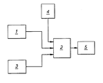
- the invention further provides apparatus for performing the method described in the preceding paragraph, which apparatus is characterised by a first measuring station (3) having means for propagating mechanical vibrations through the thickness of the sheet and means for determining an apparent sheet thickness on the basis of an elastic property of the material which is manifest at the velocity V of the mechanical vibrations propagated through the sheet thickness, a second measuring station (1) having means for measuring true sheet thickness independently of the said elastic property of the sheet material, a computer (2) for processing the outputs from the first and second measuring stations and comparing the processed output with stored values representative of and predetermined by conventional means for that sheet material, and a display unit (5) having means for providing a direct reading of upon identity between said processed output and a said stored value.
- the invention provides apparatus for performing the method described above which is characterised by a measuring station (3) for sequentially effecting a first measurement representative of an apparent thickness of the sheet by propagating vibrations through the thickness of the sheet material and effecting a second measurement of the true thickness independently of the said elastic property of the sheet material, a computer (2) for processing the outputs from said station and comparing the processed output with stored values representative of and predetermined by conventional means for that sheet material, and a display unit (5) for providing a direct reading of upon identity between said processed output and a said stored value.
- the vibrations may be in the longitudinal mode transmitted through the thickness of the sheet normal to the surface.
- longitudinal, torsional or compound waves, eg Lamb waves may be propagated in diverse directions through the material to determine the elastic property.
- the elastic property may be a constant, eg Youngs Modulus E-the ratio of uniaxial stress to corresponding uniaxial strain-or the apparent Youngs Modulus c P in a specified direction if the material is non-isotropic, and this may be deter- . mined by measuring the transit time t/2 of a mechanical vibration transmitted through the sheet thickness and independently measuring the sheet thickness d eg by physical means such as a micrometer, by optical means, by nucleonic means, or indeed, by any other means which is unaffected by variations in elastic anisotropy.
- the elastic modulus need not be expressly depicted as such, since this property is only inherently utilised in the determination of r. Accordingly, in one practical embodiment a micrometer measurement is first made of the true thickness of the sheet material, the value d of which is electronically stored and then the transit time t of an ultrasonic pulse transmitted through this material is likewise measured and stored. Also stored is the previously determined relationship between r for that material (measured conventionally) and the velocity V of a longitudinal vibration through the material. The velocity V may thus be computed by a micro-processor from the inputs specified, the appropriate value of r being retrieved directly from memory by comparing the computed value of V with the stored equivalent.
- the true thickness being measured using a micrometer and an apparent thickness being determined by means of an ultrasonic thickness meter; these measurements and the difference between the values (adjusted to a standard thickness of sheet) are electronically stored. Also stored is the previously determined relationship for that material between r (measured conventionally) and the difference (also for the standard thickness of sheet) between thickness readings measured by the two methods above. The value of the sheet is then obtained directly by comparing the difference between the thickness readings with the stored equivalent.
- measuring station 1 provides a digital signal representative of a physical micrometer measurement of the true thickness d of a sample of sheet being assessed for drawability and the output from this unit is transmitted to and stored in a micro-processor based computer unit 2.
- Measuring station 3 embodies an ultrasonic transmitter/receiver and a timer; this station functions by timing the interval between the launch and the return of a longitudinal pulse which travels through the thickness of the sample and is reflected back from its remote face.
- the previously determined stored relationship between V and measured conventionally for the material in question is then utilised to obtain the corresponding value of r. in particular, the V, r relationship is conveniently stored in the form of a 'look up'table in memory blank 4. Alternatively, r may be obtained by evaluating each time the empirical mathematical expression for in terms of V and constants where these constants are stored as before. A combination of these two approaches is sometimes to be preferred.
- the measuring station 1 again provides a signal representative of a physical micrometer measurement of the true thickness of a sample of sheet steel whilst the station 3 provides a signal representative of apparent thickness measured ultrasonically.
- an ultrasonic thickness meter is Model No. CL 204 manufactured by Krautkramer.
- the two signals are fed to the computer unit 2, which in this instance operates to provide a measurement of the difference between these two signals adjusted to a standard thickness of sheet, eg 1 mm-since the 'measured' thickness difference will depend on the thickness of the sheet sampled.
- Memory bank 4 provides inputs representative of previously determined relationships for the various materials between r (measured conventionally) and the difference (for the standard sheet thickness) between true and apparent thickness readings measured physically and ultrasonically respectively as stated above.
- the value of the actual sample selected is then obtained directly for display on the unit 5 by comparing the difference between the thickness readings as determined by the computer 2 with the stored equivalent from the memory bank.
- both measuring stations can be constituted by a single assembly, one or both of hte micrometer anvils also serving as ultrasonic probes.
- another means may be used for the thickness measurement providing that it is unaffected by changes in elastic anisotropy, eg optical or ionising radiation means.
- the ultrasonic probes may be of the non-contact variety, eg by utilising a suitable couplant.
- the embodiments described involve measurement by the time-of- flight method, the invention would be equally applicable if measurements were made of the resonance frequency of the sample and a reference material, use being made in this instance of the relationship between resonance frequency and the velocity of propagation.
Landscapes
- Physics & Mathematics (AREA)
- Biochemistry (AREA)
- Health & Medical Sciences (AREA)
- Life Sciences & Earth Sciences (AREA)
- Chemical & Material Sciences (AREA)
- Analytical Chemistry (AREA)
- Acoustics & Sound (AREA)
- General Health & Medical Sciences (AREA)
- General Physics & Mathematics (AREA)
- Immunology (AREA)
- Pathology (AREA)
- Investigating Or Analyzing Materials By The Use Of Ultrasonic Waves (AREA)
- Length Measuring Devices Characterised By Use Of Acoustic Means (AREA)
- Investigating Strength Of Materials By Application Of Mechanical Stress (AREA)
Claims (7)

Applications Claiming Priority (2)
| Application Number | Priority Date | Filing Date | Title |
|---|---|---|---|
| GB8102185 | 1981-01-23 | ||
| GB8102185 | 1981-01-23 |
Publications (2)
| Publication Number | Publication Date |
|---|---|
| EP0057521A1 EP0057521A1 (de) | 1982-08-11 |
| EP0057521B1 true EP0057521B1 (de) | 1986-04-02 |
Family
ID=10519196
Family Applications (1)
| Application Number | Title | Priority Date | Filing Date |
|---|---|---|---|
| EP82300205A Expired EP0057521B1 (de) | 1981-01-23 | 1982-01-15 | Bestimmung der plastischen Anisotropie in plattenförmigem Material |
Country Status (6)
| Country | Link |
|---|---|
| US (1) | US4432234A (de) |
| EP (1) | EP0057521B1 (de) |
| JP (1) | JPS57147032A (de) |
| CA (1) | CA1188403A (de) |
| DE (1) | DE3270197D1 (de) |
| GB (1) | GB2091889B (de) |
Families Citing this family (17)
| Publication number | Priority date | Publication date | Assignee | Title |
|---|---|---|---|---|
| US4566336A (en) * | 1983-06-27 | 1986-01-28 | Canadian Patents & Development Ltd. Societe Canadienne Des Brevets Et D'exploitation Limited | Navigational aid alerting system |
| DE3418190A1 (de) * | 1984-05-16 | 1985-11-21 | Ernst Leitz Wetzlar Gmbh, 6330 Wetzlar | Verfahren zur datenspeicherung in und datenauslesung aus resistschichten |
| CA1264196A (en) * | 1986-07-18 | 1990-01-02 | Canadian Patents And Development Limited/Societe Canadienne Des Brevets Et D'exploitation Limitee | Method of, and an apparatus for, evaluating forming capabilities of solid plate |
| US5251486A (en) * | 1988-04-29 | 1993-10-12 | Iowa State University Research Foundation, Inc. | Method of ultrasonic measurement of texture |
| US4899589A (en) * | 1988-04-29 | 1990-02-13 | Iowa State University Research Foundation | Semi-automatic for ultrasonic measurement of texture |
| US5154081A (en) * | 1989-07-21 | 1992-10-13 | Iowa State University Research Foundation, Inc. | Means and method for ultrasonic measurement of material properties |
| WO1991013348A1 (en) * | 1990-02-26 | 1991-09-05 | Iowa State University Research Foundation, Inc. | Nondestructive ultrasonic evaluation of formability of metallic sheets |
| US5115673A (en) * | 1990-07-20 | 1992-05-26 | The United States Of America As Represented By The United States National Aeronautics And Space Administration | Non-destructive method for determining elastic moduli of material |
| US5804727A (en) * | 1995-09-01 | 1998-09-08 | Sandia Corporation | Measurement of physical characteristics of materials by ultrasonic methods |
| RU2133461C1 (ru) * | 1997-03-05 | 1999-07-20 | Акционерное общество "АвтоВАЗ" | Способ определения штампуемости тонколистового холоднокатаного проката металла для трудноштампуемых деталей |
| JP3326384B2 (ja) * | 1998-03-12 | 2002-09-24 | 古河電気工業株式会社 | 半導体ウエハーの劈開方法およびその装置 |
| RU2206883C1 (ru) * | 2001-11-01 | 2003-06-20 | Открытое акционерное общество "Новолипецкий металлургический комбинат" | Способ контроля механических свойств тонколистового проката |
| RU2229697C2 (ru) * | 2002-06-28 | 2004-05-27 | Федеральное государственное унитарное предприятие Комбинат "Электрохимприбор" | Способ определения штампуемости листов молибдена без надрыва |
| US7426865B2 (en) * | 2005-11-22 | 2008-09-23 | General Electric Company | Method for ultrasonic elastic modulus calculation and imaging |
| RU2426979C2 (ru) * | 2008-12-31 | 2011-08-20 | Открытое акционерное общество "АВТОВАЗ" | Способ испытания и оценки штампуемости листового проката |
| RU2625545C2 (ru) * | 2015-10-14 | 2017-07-14 | Федеральное государственное бюджетное образовательное учреждение высшего профессионального образования "Самарский государственный технический университет" | Способ испытаний материалов для определения силовых параметров при получении полых заготовок обработкой давлением |
| CN112033804B (zh) * | 2020-08-06 | 2024-01-05 | 中铝材料应用研究院有限公司 | 一种测量板材塑性应变比r值的方法 |
Family Cites Families (3)
| Publication number | Priority date | Publication date | Assignee | Title |
|---|---|---|---|---|
| US3812709A (en) * | 1972-02-09 | 1974-05-28 | Thermo Electron Corp | Stress gage |
| US4080836A (en) * | 1977-03-07 | 1978-03-28 | Rockwell International Corporation | Method of measuring stress in a material |
| GB2060889B (en) * | 1979-08-07 | 1983-09-28 | Magyar Aluminium | Process and apparatus for measuring anisotropy value of form changes in normal direction in sheet metals |
-
1982
- 1982-01-15 EP EP82300205A patent/EP0057521B1/de not_active Expired
- 1982-01-15 DE DE8282300205T patent/DE3270197D1/de not_active Expired
- 1982-01-19 GB GB8201498A patent/GB2091889B/en not_active Expired
- 1982-01-21 US US06/341,571 patent/US4432234A/en not_active Expired - Fee Related
- 1982-01-22 JP JP57008731A patent/JPS57147032A/ja active Pending
- 1982-01-22 CA CA000394761A patent/CA1188403A/en not_active Expired
Non-Patent Citations (1)
| Title |
|---|
| "The Measurement of Normal Plastic Anisotropy in Sheet Steel", published April 1965 in "Sheet Metal Industries" pages 3-11 * |
Also Published As
| Publication number | Publication date |
|---|---|
| GB2091889B (en) | 1984-12-19 |
| US4432234A (en) | 1984-02-21 |
| EP0057521A1 (de) | 1982-08-11 |
| DE3270197D1 (en) | 1986-05-07 |
| GB2091889A (en) | 1982-08-04 |
| CA1188403A (en) | 1985-06-04 |
| JPS57147032A (en) | 1982-09-10 |
Similar Documents
| Publication | Publication Date | Title |
|---|---|---|
| EP0057521B1 (de) | Bestimmung der plastischen Anisotropie in plattenförmigem Material | |
| Adams et al. | A vibration technique for non-destructively assessing the integrity of structures | |
| Komlos et al. | Ultrasonic pulse velocity test of concrete properties as specified in various standards | |
| Makoond et al. | Dynamic elastic properties of brick masonry constituents | |
| US6082181A (en) | Ultrasonic fluid densitometer having liquid/wedge and gas/wedge interfaces | |
| US5714688A (en) | EMAT measurement of ductile cast iron nodularity | |
| Goueygou et al. | Assessment of porosity of mortar using ultrasonic Rayleigh waves | |
| Crecraft | Ultrasonic measurement of stresses | |
| US6920790B2 (en) | Apparatus for in-situ nondestructive measurement of Young's modulus of plate structures | |
| Wiciak et al. | Sensor and dimensions effects in ultrasonic pulse velocity measurements in mortar specimens | |
| US4790188A (en) | Method of, and an apparatus for, evaluating forming capabilities of solid plate | |
| Fukuoka et al. | Nondestructive residual-stress measurement in a wide-flanged rolled beam by acoustoelasticity: Acoustoelasticity stress analysis is applied to measure residual-stress distribution in a wide-flanged rolled beam and the results are compared with those obtained by the conventional destructive method | |
| Santos et al. | Ultrasonic stress measurement using PC based and commercial flaw detectors | |
| WO1995011453A1 (en) | Strength determination of sheet materials by ultrasonic testing | |
| Komlos et al. | Comparison of five standards on ultrasonic pulse velocity testing of concrete | |
| Sun et al. | Feasibility of using Lamb waves for corrosion detection in layered aluminium aircraft structures | |
| US6575036B1 (en) | Method for in-situ nondestructive measurement of Young's modulus of plate structures | |
| Popovics et al. | Comparison of DIN/ISO 8047 (Entwurf) to several standards on determination of ultrasonic pulse velocity in concrete | |
| Van Otterloo et al. | How isotropic are quasi-isotropic laminates | |
| Hasegawa et al. | Acoustoelastic birefringence effect in wood III: ultrasonic stress determination of wood by acoustoelastic birefringence method | |
| RU2025727C1 (ru) | Способ определения коэффициента нормальной анизотропии прокатных листовых материалов | |
| Dean et al. | Aspects of modulus measurement | |
| RU2810679C1 (ru) | Ультразвуковой способ определения разности главных механических напряжений в ортотропных конструкционных материалах | |
| Jacobsson et al. | Measurement of p-and s-wave velocity in material using ultrasonics | |
| Dean | Use of plate bending waves for elastic property determination of polymers |
Legal Events
| Date | Code | Title | Description |
|---|---|---|---|
| PUAI | Public reference made under article 153(3) epc to a published international application that has entered the european phase |
Free format text: ORIGINAL CODE: 0009012 |
|
| AK | Designated contracting states |
Designated state(s): BE DE FR IT NL SE |
|
| 17P | Request for examination filed |
Effective date: 19821203 |
|
| GRAA | (expected) grant |
Free format text: ORIGINAL CODE: 0009210 |
|
| AK | Designated contracting states |
Kind code of ref document: B1 Designated state(s): BE DE FR IT NL SE |
|
| PG25 | Lapsed in a contracting state [announced via postgrant information from national office to epo] |
Ref country code: NL Effective date: 19860402 Ref country code: IT Free format text: LAPSE BECAUSE OF FAILURE TO SUBMIT A TRANSLATION OF THE DESCRIPTION OR TO PAY THE FEE WITHIN THE PRESCRIBED TIME-LIMIT;WARNING: LAPSES OF ITALIAN PATENTS WITH EFFECTIVE DATE BEFORE 2007 MAY HAVE OCCURRED AT ANY TIME BEFORE 2007. THE CORRECT EFFECTIVE DATE MAY BE DIFFERENT FROM THE ONE RECORDED. Effective date: 19860402 Ref country code: FR Free format text: THE PATENT HAS BEEN ANNULLED BY A DECISION OF A NATIONAL AUTHORITY Effective date: 19860402 Ref country code: BE Effective date: 19860402 |
|
| PG25 | Lapsed in a contracting state [announced via postgrant information from national office to epo] |
Ref country code: SE Effective date: 19860430 |
|
| REF | Corresponds to: |
Ref document number: 3270197 Country of ref document: DE Date of ref document: 19860507 |
|
| EN | Fr: translation not filed | ||
| NLV1 | Nl: lapsed or annulled due to failure to fulfill the requirements of art. 29p and 29m of the patents act | ||
| PLBE | No opposition filed within time limit |
Free format text: ORIGINAL CODE: 0009261 |
|
| STAA | Information on the status of an ep patent application or granted ep patent |
Free format text: STATUS: NO OPPOSITION FILED WITHIN TIME LIMIT |
|
| 26N | No opposition filed | ||
| PG25 | Lapsed in a contracting state [announced via postgrant information from national office to epo] |
Ref country code: DE Effective date: 19871001 |