EP0057534B1 - Telegrafisches Fernmeldesystem - Google Patents
Telegrafisches Fernmeldesystem Download PDFInfo
- Publication number
- EP0057534B1 EP0057534B1 EP82300293A EP82300293A EP0057534B1 EP 0057534 B1 EP0057534 B1 EP 0057534B1 EP 82300293 A EP82300293 A EP 82300293A EP 82300293 A EP82300293 A EP 82300293A EP 0057534 B1 EP0057534 B1 EP 0057534B1
- Authority
- EP
- European Patent Office
- Prior art keywords
- line
- current
- teleprinter
- reception
- polarity
- Prior art date
- Legal status (The legal status is an assumption and is not a legal conclusion. Google has not performed a legal analysis and makes no representation as to the accuracy of the status listed.)
- Expired
Links
Images


Classifications
-
- H—ELECTRICITY
- H04—ELECTRIC COMMUNICATION TECHNIQUE
- H04L—TRANSMISSION OF DIGITAL INFORMATION, e.g. TELEGRAPHIC COMMUNICATION
- H04L25/00—Baseband systems
- H04L25/02—Details ; arrangements for supplying electrical power along data transmission lines
- H04L25/0264—Arrangements for coupling to transmission lines
- H04L25/0266—Arrangements for providing Galvanic isolation, e.g. by means of magnetic or capacitive coupling
- H04L25/027—Arrangements for providing Galvanic isolation, e.g. by means of magnetic or capacitive coupling specifically for telegraph signals
Definitions
- This invention relates to telegraphic communication system with automatic handling of irregularities in connection of a transmission-reception line of a telegraphic station, the line normally carrying a predetermined current, comprising a polarity detector in series with the line to detect the current polarity, sensing means for sensing an absence of circulating current in the line for a time period exceeding a predetermined period, indicating means settable by the sensing means for indicating absence of the circulating current on the line, and a device operable for reversing the connection of the line in dependence upon the detector if a connection reversal takes place during the current absence, see for example GB-A-1575326.
- This situation is detected by a circuit in the teleprinter which after a predetermined time period automatically switches over the polarity of the line connections, in order to reestablish the correct direction of current circulation.
- the object of the invention is to provide a telegraphic communication system in which erroneous polarity reversal can be positively discriminated both in a single current system and in a double current system.
- the system according to the invention is characterised as set out in claim 1 below.
- a single current telegraphic communication system comprises an electronic teleprinter 1 connected by a two-wire line 2 to an exchange 3.
- the teleprinter 1 comprises essentially a keyboard 80, a printer 81 and a line interface 82, which are connected by way of a bus 83 to a central unit (CPU) 84.
- CPU central unit
- This is of the microprocessor type, and cooperates by way of the bus 83 with a working RAM 86 under the control of a ROM 87 permanently storing a series of microprograms or instruction routines, T, S, A, B etc, known as handlers.
- the functions of the teleprinter 1 are controlled both in reception and in transmission by the CPU 84 which processes the microprograms contained in the memory 87 substantially in the manner described in our published United Kingdom patent application No. GB 2078062.
- the line 2 is of the "signle current” type, composed of only two wires 4 and 5, through which a current circulates, modulated as required, for reception or for transmission.
- the current is circulated in the line 2 by a generator 6 in the exchange 3 (represented as a battery), to selectively provide a positive voltage at the wire 4 and a negative voltage at the wire 5 or vice versa, as shown diagrammatically by an arrangement of connections 7.
- a switch 8 in the exchange 3 diagrammatically indicates the possibility of modulating the current circulating in the line 2 in order to feed messages from the exchange 6 to the teleprinter 1.
- the generator 6 and switch 8 are connected to the line 2 of each teleprinter 1 by a corresponding connection circuit 16, of which only two are shown in Figure 1. It is therefore possible to connect together any two teleprinters 1 by way of the exchange 3.
- a switch 11 indicates a signal modulation member for feeding messages from the teleprinter 1 to the exchange 3.
- a switch 9 selectively shunts a resistor 10 in series with the wires 4 and 5, in order to select currents of the value of 40 mA representing the transmitted signals when the switch 9 is closed, and currents of 5 mA representing idling signals when the switch 9 is open.
- the current signals used for transmitting messages from or towards the teleprinter 1 are the 40 mA signals.
- the teleprinter 1 comprises means arranged to generate a signal FINC in known manner to indicate the termination of a transmission-reception operation.
- This termination signal is generated on the basis of a command from the CPU processor 84 either at the end of a message transmitted by the teleprinter 1, or following an end-of-transmission signal originating from the exchange 3.
- the diagram 88 represents a connection made as the result of a call signal originating from the teleprinter 1.
- the call begins with the closure of the switch 9, which generates a signal 89 of -40 mA, to which the exchange 3 replies by opening the switch 8 in order to generate a current interruption 90 which represents a request to the teleprinter 1 to dial the distant station.
- the dialling operation is indicated in the diagram by a series of signals 91.
- the connection having been made at 92, the exchange 3 reverses the connection of the generator 6 by way of the connections 7, so that the message is transmitted with a sequence of +40 mA signals 93.
- an end-of-message code is transmitted by the teleprinter, which causes the CPU 84 to emit a FINC signal, causing the switch 11 to open.
- the exchange 3 makes a new reversal of the connections 7 with a predetermined delay, so that circulation of the idling current of -5 mA is restored at 94.
- the teleprinter 1 can also be connected by a call signal originating from the exchange and thus entering the teleprinter.
- the exchange 3 commences with a reversal of the connections 7, to induce the call signal 96 of +5 mA in the line.
- the teleprinter 1 recognises the call signal and closes the switch 9, so that the message becomes transmitted by means of a sequence of +40 mA signals 97.
- the exchange 3 transmits the end-of-message code, causing the teleprinter switch 11 to open, and restores the -5 mA current by way of the connections 7, as in the preceding case.
- connection is called a "false connection".
- the aforesaid connection procedures are known and are schedule by international regulations, so that they require no further description.
- the teleprinter 1 receives a signal of +5 mA.
- This signal is indicated at 20 on a corresponding diagram 98 of Figure 2.
- the teleprinter interprets the signal 20 as a call by the exchange 3 (see signat96), so that it closes the switch 9 in order to generate a current of +40 mA. This generates a signal 21 representing recognition of the connection requested by the exchange 3.
- the currents circulating through the exchange 3 are now of opposite polarity to those circulating through the teleprinter 1, as indicated by the diagram 99 of Figure 2, so that to the signal 21 there now corresponds a signal 22 which the exchange interprets however as a call by the teleprinter 1 (see signal 89).
- the exchange 3 thus transmits a current interruption 23 while awaiting the dialling operation, whereas the teleprinter interprets this interruption as part of the message being received.
- the exchange 3 transmits the end-of-operation code which begins with a positive signal 24. This is received by the teleprinter as a negative signal 26, in response to which the CPU 84 generates the signal FINC, causing the switch 11 to open as at the end of a regular transmission.
- the current due to the signal 24 now falls temporarily to +5 mA in the exchange 3, and to -5 mA in the teleprinter 1.
- the exchange 3 again reverses the connections 7, so that the signal 20 is restored together with the initial conditions, which again determine circulation of a current of +5 mA (full line) instead of the regular current of -5 mA (indicated by the dashed line).
- the false connection operations now described are therefore repeated, unless any external intervention takes place.
- the teleprinter station 1 ( Figure 1) is provided with a device 29 for automatically handling connections irregularities, comprising a device 30 ( Figure 3) for reversing the connection of the two wires 4 and 5, which is connected in series with the line 2, and a current polarity detector 31 connected in series with the wire 5.
- the teleprinter 1 also comprises an alarm device constituted by a warning light 28 disposed on the keyboard 80 and arranged to light intermittently under the control of the CPU 84 when certain abnormal conditions occur, as will be more apparent hereinafter.
- the alarm device can be a buzzer or other acoustic device.
- the reversing device 30 is controlled by a reversing signal REV activated by the CPU processor 84 of Figure 1.
- the signal REV when activated, energises an electromagnet 36 by way of a resistor 34 and transistor 35, this electromagnet changing-over a two-pole changeover switch 37 from a first to a second position.
- the switch 37 When in its first position, the switch 37 connects the wire 4 to the wire 4' and the wire 5 to the wire 5', while when in its second position it connects the wire 4 to the wire 5' and the wire 5 to the wire 4', so reversing the polarity of the current circulating through the line 2 within the teleprinter.
- the polarity detector 31 comprises at least one optoelectric coupler, and is connected in series with the line 2 in the manner described in ou UK patent specification GB 1 575 326.
- the detector 31 provides two signals NEG and POS continuously, at logic levels depending on the direction of the circulating current in the line 2.
- the signal NEG is low while the signal POS is high. If the current circulating through the line 2 has a negative direction, the signal POS is low and the signal NEG is high, whereas if current is absent both the signals POS and NEG are low.
- the signals NEG and POS at low logic level activate a signal ZER at the input to a timing counter 41 by way of an AND gate 40.
- the counter 41 is set to run when ZER is high to provide an output signal INT after a period of 5 seconds.
- the signal INT is thus set to the high logic level "1" only if current is absent from the line for an interval of at least 5 seconds.
- the signal ZER returns to low logic level, and its negative transition deactivates the counter 41 and resets it to "0".
- the signal INT cannot be activated because the counter 41 becomes deactivated before this, so that the signal INT thus generated indicates that current has not been circulating through the wire 5 for at least 5 seconds.
- the signals NEG, POS and INT are used by the CPU 84 in the manner described hereinafter.
- a teleprinter 45 ( Figure 4) is connected to an exchange 46 by a "double current" line 47, the two wires 54 and 55 which comprise the line 47 are electrically independent and serve for transmitting messages from the teleprinter 45 to the exchange 46 and for receiving at the teleprinter 45 from the exchange 46 respectively, both wires operating in conjunction with a common earth return.
- the teleprinter 45 is provided with a keyboard 80 with an alarm device 28, a printer 81, a CPU 84 and memories 86 and 87, corresponding to those of the teleprinter 1 of Figure 1.
- the line interface 82 of the teleprinter 45 ( Figure 4) likewise comprises a device 29 for automatically handling connection irregularities.
- the interface 82 of the teleprinter 45 now comprises a transmission device 56 indicated diagrammatically by means of a current generator 57 able to feed a current of ⁇ 20 mA through the wire 54.
- the current through the line 47 is modulated between the two levels +20 mA and -20 mA in order to transmit messages through the wire 54 to a corresponding reception device 58 disposed in the exchange 46.
- a transmission device 59 disposed in the exchange 46 and indicated diagrammatically by means of a current generator 60 is associated with the teleprinter 45, and feeds currents through the wire 55 to a reception device 61 in the teleprinter 45.
- the exchange 46 thus comprises one transmission device 59 and one reception device 58 for each teleprinter 45, a known selection unit 62 being actuated by the dialling operation in order to connect two teleprinters 45 together.
- the transmission and reception devices of the teleprinter 45 for double current operation are controlled by the CPU 84, which processes the programs contained in the memory 87.
- Figure 5 shows two current levels of -20 and +20 mA during the idling stage and during a transmission respectively.
- the diagram 70 represents the current through the reception wire 55 for a connection made from the teleprinter 45, and is analogous to the diagram 88 ( Figure 2).
- the zone 72 indicates the modulation during the reception.
- the diagram 71 indicates the current through the transmission wire 54 as a result of the outgoing call, in which the zone 73 represents the dialling and the zone 74 represents the modulation during the transmission.
- the diagrams 76 and 77 represent the currents for a call entering the teleprinter through the transmission wire 54 and reception wire 55. It is therefore apparent that the current circulating through the wire 54 or wire 55 is never zero.
- the device 29 is again disposed with the reversing device 30 ( Figure 6) in series with the transmission wire 54 and reception wire 55, in such a manner as to be able to reverse their connections to the teleprinter, while the polarity detector 31 is connected in series with the reception wire 55 to detect the absence of current which occurs if the two reception devices 58 and 61 of Figure 4 are erroneously connected together.
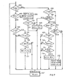
- the selection 104 checks the FLAG condition stored in the cell 65 of the memory 86. This condition indicates the need to check the circulating current through the line 2 if at logic level "1", whereas it allows execution of other programs if at logic level "0".
- a block 107 which generally indicates the execution of control programs for supervising the teleprinter 1.
- These programmes can be processes by the CPU 84, either to locally control the teleprinter 1 and possibly its peripherals, or to control the line. Obviously, as the call has been deactivated, only local control is allowed.
- the block 107 is followed by the selection 104, which following the operation 106 now has a positive result.
- the selection 102 is then made, and as the operation is of single current type, the selections 109, 103 and 110 are made in sequence.
- the selections 109 and 110 indicate examination of the signals NEG and POS respectively from the polarity detector 31 of Figure 3, so that these represent the checks on the line circulation current.
- the signals NEG and POS both remain at logic level "0", and consequently the selection 109 and the selection 110 have a negative result, and a return is made to local control as represented by the block 107.
- the block 107 is again followed by the selection 104 with positive result. Consequently, if the line interruption remains, the line checking operations 102-110 are repeated, with the alarm situations as listed in the block 106 maintained.
- the instant 129 indicates the cessation of the idling current following an interruption in the line 2. 5 seconds after the execution of the operations 106 of Figure 7, defined by the counter 41 ( Figure 3), the alarm signal is activated as indicated at the instant 130 on the diagram 122 of Figure 8. Repeated polarity checking operations 131 then take place, while the alarm situation remains.
- the selection 109 of Figure 7 has a positive result.
- a test waiting time of the order of 100 msec produces a negative result for the selection 111, which is followed by the operations 107-109 and thus the repetition of the current polarity checks, possibly interspersed by other local control operations 107, until the test time has run out.
- a group of operations 112 is carried out in which FLAG is set to "0", the alarm 28 is turned off and the call signals are again authorised.
- the correct restoration is represented by the continuous line at the instant 132, which is followed by the test at the instant 133. As the result of this test is assumed positive, the alarm reset is produced, visible in the diagram 121.
- operation 114 is carried out, representing the reversing command actuated by the signal REV ( Figure 3), which is fed to the input of the polarity reversing device 30 to produce reversal of the connections of the line 2.
- REV the signal
- Figure 7 the correct idling current of -5 mA must circulate through the line, and this, checked once again by the selection 109 ( Figure 7) produces execution of the operations 112, and the teleprinter returns to normal operation.
- Figure 8 shows the polarity reversal by means of the dashed line 133 produced after the last test.
- the selection 105 ( Figure 7) is now followed by the selection 100 and by a selection 115 dependent on the end-of-transmission signal FINC. After a delay of about 1 second (waiting time 116), the selection 115 again determines activation of the FLAG at logic level "1" (operation 117).
- test indicated at point 116 follows each activation of the end-of-transmission signal FINC ( Figure 2) with the said delay (necessary to allow any transient phenomena to die out), to check the direction of the current under idling conditions. This is then followed by the block 107 ( Figure 7) and the selection 104 with positive result, which produces the tests and any line reversals described by the blocks 109-114.
- the selection 109 gives a negative result, this is due to the fact that the correct current has not yet been established in the wire 55.
- the selections 103, 107, 104 and 102 follow, and the checks on the current flowing through the wire 55 of Figure 6 are repeated.
- the result of the selection 129 is positive, the line reversal 120 is again actuated, and the operations 107 and 104 are repeated until negative current is restored in the wire 55.
- the diagram 123 of Figure 8 schematically shows the interruption of the current in the line 47 at an instant 140, while the diagram 124 schematically shows the alarm indication.
- the first line reversal operation takes place, followed by other reversals 142, 143 and 144 separated by periods of 5 seconds. It has been assumed that the reversals 141-144 have no effect on the line current.
- the correct idling current returns, and the alarm conditions are obviously reset.
- the teleprinter stations can be connected by so-called point-to-point lines.
- the automatic handling of the transmission-reception irregularities can be easily deduced from the description already given.
- this handling can apply to irregularities in connection types which are different from that described.
Landscapes
- Engineering & Computer Science (AREA)
- Power Engineering (AREA)
- Computer Networks & Wireless Communication (AREA)
- Signal Processing (AREA)
- Monitoring And Testing Of Exchanges (AREA)
- Dc Digital Transmission (AREA)
- Maintenance And Management Of Digital Transmission (AREA)
Claims (7)
Applications Claiming Priority (2)
| Application Number | Priority Date | Filing Date | Title |
|---|---|---|---|
| IT67122/81A IT1143332B (it) | 1981-01-30 | 1981-01-30 | Sistema di comunicazioni telegrafiche con gestione automatica delle irregolarita di collegamento |
| IT6712281 | 1981-01-30 |
Publications (3)
| Publication Number | Publication Date |
|---|---|
| EP0057534A2 EP0057534A2 (de) | 1982-08-11 |
| EP0057534A3 EP0057534A3 (en) | 1982-08-25 |
| EP0057534B1 true EP0057534B1 (de) | 1985-04-17 |
Family
ID=11299770
Family Applications (1)
| Application Number | Title | Priority Date | Filing Date |
|---|---|---|---|
| EP82300293A Expired EP0057534B1 (de) | 1981-01-30 | 1982-01-20 | Telegrafisches Fernmeldesystem |
Country Status (6)
| Country | Link |
|---|---|
| US (1) | US4434324A (de) |
| EP (1) | EP0057534B1 (de) |
| JP (1) | JPS57147357A (de) |
| BR (1) | BR8200496A (de) |
| DE (1) | DE3263056D1 (de) |
| IT (1) | IT1143332B (de) |
Families Citing this family (12)
| Publication number | Priority date | Publication date | Assignee | Title |
|---|---|---|---|---|
| JPH0681159B2 (ja) * | 1987-11-13 | 1994-10-12 | 三菱電機株式会社 | 情報伝送装置 |
| JPH0691557B2 (ja) * | 1988-02-17 | 1994-11-14 | 三菱電機株式会社 | 情報伝送装置 |
| JPH0691556B2 (ja) * | 1988-01-19 | 1994-11-14 | 日本電気株式会社 | ペアケーブル用ディジタル伝送方式 |
| JPH0687564B2 (ja) * | 1988-01-19 | 1994-11-02 | 日本電気株式会社 | ペアケーブル用ディジタル伝送方式 |
| US5581744A (en) * | 1993-11-29 | 1996-12-03 | Andrew Corporation | Method and apparatus for correcting polarity using a synchronizing sequence |
| DE19606910B4 (de) * | 1996-02-19 | 2005-12-29 | Abb Patent Gmbh | Verfahren zur Anpassung des empfangsseitigen Logikpegels an seriellen Lichtwellenleiterschnittstellen |
| US6252756B1 (en) * | 1998-09-18 | 2001-06-26 | Illinois Tool Works Inc. | Low voltage modular room ionization system |
| TW403872B (en) * | 1998-12-09 | 2000-09-01 | Topic Semiconductor Corp | Auto-line connected network device |
| TWI301372B (en) * | 2006-04-21 | 2008-09-21 | Hon Hai Prec Ind Co Ltd | System and method for auto-reversing loop polarity of u interface |
| CN101064751B (zh) * | 2006-04-28 | 2011-06-08 | 鸿富锦精密工业(深圳)有限公司 | U接口回路极性自动反转系统及方法 |
| US8479065B2 (en) | 2011-11-02 | 2013-07-02 | Arinc Incorporated | Adaptive, wireless automatic identification system pilot port interface |
| JP2019192616A (ja) * | 2018-04-27 | 2019-10-31 | シャープ株式会社 | 接続装置、及び制御装置 |
Family Cites Families (5)
| Publication number | Priority date | Publication date | Assignee | Title |
|---|---|---|---|---|
| US3458727A (en) | 1966-01-03 | 1969-07-29 | Gen Electric | Polar telegraphy receive current loop with solid-state switching bridge |
| JPS5743955B2 (de) * | 1973-06-18 | 1982-09-18 | ||
| JPS5036002A (de) * | 1973-08-03 | 1975-04-04 | ||
| IT1072336B (it) * | 1976-05-18 | 1985-04-10 | Olivetti & Co Spa | Circuito telegrafico |
| JPS5373005A (en) * | 1976-12-13 | 1978-06-29 | Taiko Electric Works Ltd | Automatic channel converting system for automatic call answering device |
-
1981
- 1981-01-30 IT IT67122/81A patent/IT1143332B/it active
-
1982
- 1982-01-20 EP EP82300293A patent/EP0057534B1/de not_active Expired
- 1982-01-20 DE DE8282300293T patent/DE3263056D1/de not_active Expired
- 1982-01-27 US US06/343,311 patent/US4434324A/en not_active Expired - Fee Related
- 1982-01-29 JP JP57013187A patent/JPS57147357A/ja active Pending
- 1982-01-29 BR BR8200496A patent/BR8200496A/pt not_active IP Right Cessation
Also Published As
| Publication number | Publication date |
|---|---|
| IT1143332B (it) | 1986-10-22 |
| DE3263056D1 (en) | 1985-05-23 |
| US4434324A (en) | 1984-02-28 |
| EP0057534A3 (en) | 1982-08-25 |
| BR8200496A (pt) | 1982-11-30 |
| EP0057534A2 (de) | 1982-08-11 |
| JPS57147357A (en) | 1982-09-11 |
| IT8167122A0 (it) | 1981-01-30 |
Similar Documents
| Publication | Publication Date | Title |
|---|---|---|
| EP0057534B1 (de) | Telegrafisches Fernmeldesystem | |
| US4159470A (en) | Data communications systems employing redundant series transmission loops | |
| US4056684A (en) | Surveillance system | |
| US4270205A (en) | Serial line communication system | |
| US4506357A (en) | Method and apparatus for switching loop type transmission lines | |
| US4068105A (en) | Central station system transmission apparatus | |
| US4290136A (en) | Circuit arrangement for monitoring the state of signal systems, particularly traffic light signal systems | |
| KR860001658A (ko) | 자동 루우프 구성 제어수단을 가진 루우프 전송 시스템 | |
| EP0738059A2 (de) | Verfahren und Vorrichtung zum Prüfen von Verbindungen zwischen Netzvermittlungsknoten | |
| EP0023160A1 (de) | Digitales Fernsteuersystem | |
| US4328586A (en) | Optically coupled serial communication bus | |
| US4390947A (en) | Serial line communication system | |
| US4888586A (en) | Data transmission system | |
| US4864603A (en) | Method of transmission of information or measurement data and device for using the method | |
| US5650762A (en) | Fire alarm system | |
| GB2178878A (en) | Alarm system with priority override | |
| WO1987000395A1 (en) | Fault monitoring apparatus and monitoring system therefor | |
| US5969956A (en) | Method and a device for communication in a high voltage converter station | |
| JPS57173245A (en) | Data transmission system | |
| US3452329A (en) | Supervisory control system | |
| GB1575326A (en) | Telegraph circuit | |
| US4327409A (en) | Control system for input/output apparatus | |
| GB2051438A (en) | Security alarm systems | |
| US3513255A (en) | Control signals for use with teletypewriter apparatus | |
| US5266943A (en) | Data transmission system |
Legal Events
| Date | Code | Title | Description |
|---|---|---|---|
| PUAI | Public reference made under article 153(3) epc to a published international application that has entered the european phase |
Free format text: ORIGINAL CODE: 0009012 |
|
| PUAL | Search report despatched |
Free format text: ORIGINAL CODE: 0009013 |
|
| AK | Designated contracting states |
Designated state(s): DE FR GB |
|
| AK | Designated contracting states |
Designated state(s): DE FR GB |
|
| 17P | Request for examination filed |
Effective date: 19830201 |
|
| GRAA | (expected) grant |
Free format text: ORIGINAL CODE: 0009210 |
|
| AK | Designated contracting states |
Designated state(s): DE FR GB |
|
| REF | Corresponds to: |
Ref document number: 3263056 Country of ref document: DE Date of ref document: 19850523 |
|
| ET | Fr: translation filed | ||
| PLBE | No opposition filed within time limit |
Free format text: ORIGINAL CODE: 0009261 |
|
| STAA | Information on the status of an ep patent application or granted ep patent |
Free format text: STATUS: NO OPPOSITION FILED WITHIN TIME LIMIT |
|
| 26N | No opposition filed | ||
| PGFP | Annual fee paid to national office [announced via postgrant information from national office to epo] |
Ref country code: DE Payment date: 19930209 Year of fee payment: 12 |
|
| PGFP | Annual fee paid to national office [announced via postgrant information from national office to epo] |
Ref country code: GB Payment date: 19940111 Year of fee payment: 13 Ref country code: FR Payment date: 19940111 Year of fee payment: 13 |
|
| PG25 | Lapsed in a contracting state [announced via postgrant information from national office to epo] |
Ref country code: DE Effective date: 19941001 |
|
| PG25 | Lapsed in a contracting state [announced via postgrant information from national office to epo] |
Ref country code: GB Effective date: 19950120 |
|
| GBPC | Gb: european patent ceased through non-payment of renewal fee |
Effective date: 19950120 |
|
| PG25 | Lapsed in a contracting state [announced via postgrant information from national office to epo] |
Ref country code: FR Effective date: 19950929 |
|
| REG | Reference to a national code |
Ref country code: FR Ref legal event code: ST |