EP0057541A1 - Einzelschleifensteuerungssysteme - Google Patents
Einzelschleifensteuerungssysteme Download PDFInfo
- Publication number
- EP0057541A1 EP0057541A1 EP82300338A EP82300338A EP0057541A1 EP 0057541 A1 EP0057541 A1 EP 0057541A1 EP 82300338 A EP82300338 A EP 82300338A EP 82300338 A EP82300338 A EP 82300338A EP 0057541 A1 EP0057541 A1 EP 0057541A1
- Authority
- EP
- European Patent Office
- Prior art keywords
- microprocessor
- display
- controller
- keyboard
- instrument
- Prior art date
- Legal status (The legal status is an assumption and is not a legal conclusion. Google has not performed a legal analysis and makes no representation as to the accuracy of the status listed.)
- Withdrawn
Links
Images


Classifications
-
- G—PHYSICS
- G05—CONTROLLING; REGULATING
- G05B—CONTROL OR REGULATING SYSTEMS IN GENERAL; FUNCTIONAL ELEMENTS OF SUCH SYSTEMS; MONITORING OR TESTING ARRANGEMENTS FOR SUCH SYSTEMS OR ELEMENTS
- G05B19/00—Program-control systems
- G05B19/02—Program-control systems electric
- G05B19/18—Numerical control [NC], i.e. automatically operating machines, in particular machine tools, e.g. in a manufacturing environment, so as to execute positioning, movement or co-ordinated operations by means of program data in numerical form
- G05B19/19—Numerical control [NC], i.e. automatically operating machines, in particular machine tools, e.g. in a manufacturing environment, so as to execute positioning, movement or co-ordinated operations by means of program data in numerical form characterised by positioning or contouring control systems, e.g. to control position from one programmed point to another or to control movement along a programmed continuous path
- G05B19/39—Numerical control [NC], i.e. automatically operating machines, in particular machine tools, e.g. in a manufacturing environment, so as to execute positioning, movement or co-ordinated operations by means of program data in numerical form characterised by positioning or contouring control systems, e.g. to control position from one programmed point to another or to control movement along a programmed continuous path using a combination of the means covered by at least two of the preceding groups G05B19/21, G05B19/27 and G05B19/33
-
- G—PHYSICS
- G05—CONTROLLING; REGULATING
- G05B—CONTROL OR REGULATING SYSTEMS IN GENERAL; FUNCTIONAL ELEMENTS OF SUCH SYSTEMS; MONITORING OR TESTING ARRANGEMENTS FOR SUCH SYSTEMS OR ELEMENTS
- G05B2219/00—Program-control systems
- G05B2219/30—Nc systems
- G05B2219/41—Servomotor, servo controller till figures
- G05B2219/41255—Mode switch, select independent or dependent control of axis
-
- G—PHYSICS
- G05—CONTROLLING; REGULATING
- G05B—CONTROL OR REGULATING SYSTEMS IN GENERAL; FUNCTIONAL ELEMENTS OF SUCH SYSTEMS; MONITORING OR TESTING ARRANGEMENTS FOR SUCH SYSTEMS OR ELEMENTS
- G05B2219/00—Program-control systems
- G05B2219/30—Nc systems
- G05B2219/42—Servomotor, servo controller kind till VSS
- G05B2219/42033—Kind of servo controller
Definitions
- This invention is concerned to provide a single loop control (SLC) system that may be used for process control.
- SLC single loop control
- Process control systems are used in numerous applications to regulate one or more parameters of a process.
- Most control systems are closed-loop control systems in which information about a controlled variable is fed back to a controller to serve as the basis for control of one or more process variables.
- a siggal. representative of the controlled variable is compared by the controller with a preset desired " value, or set point, of the controlled variable. If there is a difference, the controller produces an output such as to reduce the difference by manipulating one or more of the process variables.
- the controlled variable might be the temperature of an effluent stream from a mixing tank: and the process variables might be the temperature and flow rate of the stream emptying into the tank as well as the speed of a mixer in the tank. If the temperature of the effluent is too low, the controller might open a little more a valve regulating the flow of one of the streams emptying into the tank or adjust the speed of the mixer.
- the best controller is one which provides proportional, integral and derivative (PIO) control.
- PIO proportional, integral and derivative
- Proportional control of a first order process reduces the time constant of the system and the apparent gain of the process. However, it also introduces a deviation, or offset, between the time average of the controlled variable and the set point. This offset can be compensated for by providing for integral, or reset, control in addition to proportional control.
- integral control tends to slow the response of the system, deri; vative control counters this by tending to anticipate where a process is going so that it can correct for the change in error.
- the PID transfer function is given by the following equation: where M is the manipulated variable, E is the error, K c is the controller fain, T i is the reset time and T d is the rate or derivative time.
- M is the manipulated variable
- E is the error
- K c is the controller fain
- T i is the reset time
- T d is the rate or derivative time.
- a microprocessor based single loop control instrument comprising a first microprocessor, a read only memory in which is stored an operating programr for said first microprocessor, said program containing machine instructions sufficient to perform a single loop control algorithm which produces an output signal in response to at least a process variable and a setpoint and sufficient to operate said control instrument as one of at least two different types of controllers each having at leasst two operating modes, means for causing said control instrument to operate as one of the controller types provided for by the program stored in said read only memory, and means for selecting the mode of operation of the controller selected by said causing means.
- a microprocessor based single loop control instrument comprising a first microprocessor, a read only memory in which is stored an operating program for said first microprocessor, said program containing machine instruction sufficient to perform a single loop control PID algorithm which produces an output signal in response to at least a process variable and a setpoint and sufficient to operate said control instrument as one of at least two different types of controllers each having at least two operating modes,means for causing said control instrument to operate as one of the controller types provided for by the program stored in said read only memory, a communication bus connected to said first microprocessor, and a control panel that comprises a second microprocessor connected to said communication bus, a bar graph display controlled by said second microprocessor for displaying at least one signal related to the operation of said control instrument, means for selecting the mode of operation of the controller selected by said means, and means for selecting at least one of the signals displayed by said bar graph display.
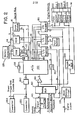
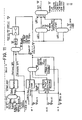
- FIG. 1 is a schematic diagram of a SLC system of the present invention comprising controler circuit board 10, a front panel board 20, an auxiliary board 30, a mother board 40 and an I/O termination board 50.
- controller board 10 Connected to each of controller board 10, front panel board 20, and auxilary board 30 are intelligent keyboard/displays 12, 22,32, respectively.
- controller board 10 Also connected to controller board 10 are an output module 14 and a serial communication module 16.
- I/O termination board 50 provides a power connector 52, a remote front panel connector 54, a communication connector 56 and a termination connector 58.
- a remote termination board 60 is connected to the I/O termination connector 58.
- Up to eight DIP switches 70 provide voltage or current selection for the analog inputs to the SLC system. For convenience, the function of various leads between the individual boards has been indicated; and where a single drawing line is used to represent more than one lead, the number of leads so represented is indicated by a numberal accompanying a slash mark through the drawing line:
- controller board 10 provides the main control for the system.
- each of controller board 10, front panel board 20, auxiliary board 30, the intelligent keyboard/displays 12,22 and 32, and the serial communication module 16 contains its own microcomputer in the form of a microprocessor and read only memory.
- Front panel board 20 provides a series of control switches and displays which may be located a considerable distance from the controller and other elements of the system.
- Auxiliary board 30 functions as a backup for controller board 10 and is switched into operation by relay 45 on mother board 40 if the processor of controller board 10 should fail.
- the intelligent keyboard/displays 12,22 and 32 are identical and provide a means for reading data from and writing data into a random access memory on controller board 10.
- the serial communication module 16 provides a means for converting parallel dats from the controller board 10 to serial data that is compatable with standard interfaces such as the RS232 and RS423 interfaces.
- the microcomputer that is resident on controller board 10 is shown in greater detail in Figure 2.
- the computer comprises a microprocessor 100, an.8 MHz crystal oscillator 105, a latch 110, a random access memory (RAM) 120, a memory protection circuit 125, aread only memory (ROM) . 130, serial communication module 16, an input protection and filtering circuit 140, an analog multiplexer 150, I/0 expanders 160, 170, 180, a digital to analog circuit 190, a comparator 195, a sample and hold circuit 200, a set of switches 210, a wave-shaping circuit 215, output module 14, a communications multiplexer 240 and connectors 250 and 255.
- Microprocessor 100 may, for example, be an intel 8039/8049 microprocessor.
- Latch 110 is a 373- type octal 0-type flip-flop which controls an address bus 112 in response to a signal from microprocessor 100.
- Address bus 112 provides eight bits of address to each of RAM 120, ROM 130 and the communication module 16. Data from these units is returned to microprocessor 100 on an eight bit parallel data bus 114.
- RAM 120 is a pair of 5101-type 256 x 4 bit CMOS memory chips connected together to provide 256 bytes of random access storage. Two control lines from microprocessor 100 control the operation of writing into and reading from these chips.
- the data stored in RAM 120 includes all programming options and tuning parameters.
- ROM 130 is three units of 2K X 8 bit memory such as a 2716-type read only memory. Each of these units is addressed by the eight address lines of bus 112 and three additional address lines. Two additional lines plus control logic (not shown) select the individual ROM chip.
- the operating program for the controller is stored in ROM 130.
- This program enables the controller to function as any one of the following seven types (or models) of controllers, a local/manual controller; a local/manual/remote controller; a local/manual/computer controllers an automatic/manual/direct digital control (ddc) controller; a local/manual/ratio controllers a cascade controllers; an auto select oontroller. Extensive details concerning these controllers are set forth below.
- the particular types of controller is determined by the positions of three of swiches 210 which are read by microprocessor 100.
- analog multiplexer 150 illustratively is a 4051-type one-out-of-eight multiplexer whose output is selected by three of the lines from I/0 expander 160 and whose operation is controlled by a fourth such line.
- the analog output of multiplexer 150 is converted to a digital signal by means of twelve bit digital-to-analog converter 190, comparator 195 and a standard analog-to-digital programming routine which is executed by microprocessor 100.
- I/0 expanders 160, 170, 180 are connected to microprocessor 100 via data bus 116 and select lines 118.
- 1/0 expander 170 provides for signal inputs from four digital inputs and twelve switches 210.
- the digital inputs are applied to I/O expander 170 from wave-shaping circuits 215 which comprises conventional level shifters and Schmitt triggers.
- the twelve switches are used to configure the software for various options. As noted above, three of the switches determine which of the seven types of controllers is operative on the controller board and front panel board.
- Additional switches permit the selection of one of four possible outputs from output module 14, the units (minutes or seconds, inverse or not) in which the PID constants are expressed, analog output range (1-5 volts or 0-5 volts), and features such as advanced tuning, computer signal type for the local/manual/computer and local/manual/ddc controllers and start-up mode.
- 1/0 expander 180 provides for two digital inputs, four digital outputs as well as analog output through sample and hold circuit 200 and/or output module 14.
- module 14 provides for the connection of one of four output modules to output lines OUT 1 and OUT 2: a pulse output module 222, stopper output module 224, and two analog output modules, the first being a floating current output module 226 and the second a common ground output module 228.
- the stopper output module 224 provides a two phase output of +24 volt signals to drive a stepper motor.
- Software routines generate the phase shift for the desired direction as well as control the stapping frequency.
- the pulse output module 222 previos raise and lower signals which can be used with solid state relays (not shown) to drive AC motors which open and close a valve, or with conventional electromechanical relays.
- the floating current output module 226 provides an analog output voltage on output line OUT 1 and a floating current output of 4 to 20 milliAmps on output line OUT 2.
- the common ground output module 228 provides an analog output voltage an output line OUT 1 and a common ground current output of 0 to 20 mA on output line OUT 2. In the absence of any output module, an analog voltage signal is present on output line OUT 1, The analog voltage signal from sample and hold circuit 200 may be fed back to microprocessor 100 through analog multiplexer 150 to compensate for drift and effset.
- Communication multiplexer 240 is a 75138-type multiplexer which is used to multiplex incoming and outgoing clock and data signals.
- Connector 250 provides for the transmission of clock, data, raise and lower signals between the microprocessors of controller board 10, front panel board 20 and auxiliary board 30.
- the four bit bus to connector 250 of Figure 2 is the same as the four bit communication bus 25 of Fi g urel This bus permits the controller board 10, front panel board 20 and auxiliary board 30 to be mounted either as an integral unit or for the front panel board to be remote by up to several hundred feet with no difference in the boards or their functions.
- Connector 255 provides for the trarsmission of clock and data signals to and from theintelligent keunoard/display 12. The signals from keuboard/display 12 are therefore present on the communication bus and are processed by the microprocessors of the boards to which the bus is connected.
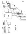
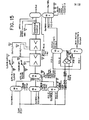
- the microcomputer that is resident on front panel board 20 is shown in greater detail in Figure 3.
- This microcomputer comprises a microprocessor 300, a 6 MHz crystal oscillator 305, a switch panel 320, an overlay 330, an array of light emitting diodes (LEDs) 340, bar graph drive electronics 360, a bar graph power supply 370, a bar graph display 380, a communications multiplexer 400 and connectors 410, 415.
- Microprocessor 300 may, for example, be an Intel 8748/8048 microprocessor.
- the microprocessor 300 controls the reading of the switches of panel 320, their debouncing and the lighting of the LEDs. It also generates the timing signals for the bar graph display so that two variables can be shown. Likewise, it can receive data from and send data to controller board 10 and auxiliary board 30.
- Front panel board 20 serves as the operator interface to such of the several different types or models of controllers listed earlier which in the present proposal share the same hardware and software,
- Switch panel 320 contains eleven switches. Depending on the particular tyoe or model of controller, up to four of these switches (M1-M4) are available for selecting the operating mode of the controller such as LOCAL or MANUAL. Again depending on the type or model, up to four switches (D1-D4) are available to select for diplay on the bar graph such parameters as process variable (PV), aetpoint (SP), and output. Three switches are available for changing displayed variables provided the displayed variable is changeable and the front/panel is in the correct mode.
- the RAISE switch ( ⁇ ) will increase the variable at a rate of 1% per seconda and the LOWER switch ( ⁇ ) will decrease the variable at the same rate.
- the FAST switch will increase the slew speed to 15% per second.
- An array of light-emitting diodes indicates the status of the switches of the switch panel as well as the availability of power (PWR) and the operating status of auxiliary board 30 (S/M). The diodes may be lighted directly by action of the switches or, as shown in Figure 3, under control of the microprocessor 300.
- a suitable form for the bar graph 380 is a commercially available dual 201 segment bar graph display such as the 12205 display available from Burroughs. Two variables are displayed simultaneously, the particular variables being selected by switches D1-D4.
- Drive electronics 360 and power supply 370 convert the low voltage level signal produced by microprocessor 300 to the high voltage level signals used by the bar graph display 380.
- a suitable form for the power supply 370 is a 24 volt to 250 volt DC to DC converter.
- Multiplexer 400 and connectors 410, 415 are similar to the multiplexer 240 and connectors 250, 255, of Figure 2; and the four bit bus to connector 410 is the same as the four bit communication bus 25 of Figure 1. If desired, multiple front panels can be connected to controller board 10 via this communication bus.
- FIG. 4A and 48 depit the s 3 ven overlays 331-337 used for the seven types of controllers that controller board 10 and front panel 20 provide. Each indicates the RAISE ( ⁇ ) and LOWER ( ⁇ ) switch as well as the FAST switch and switch to indicate status.
- the functions of the other switches shown in Figures 4A and 4B and their effect on the bar graph display are indicated in Table 1 which lists the various modes in which each of the seven types of controllers is able to operate.
- the controller In the SERVICE MANUAL mode, which features in T Table 1, the controller is not controlling the process. Its output, however, tracks the output of auxiliary board 30 which is providing manual outputs to the process. In the MANUAL mode, the output of the controller is held at a constant value unless change is specified by a manual entry. The output value may be changed by the RAISE and LOWER switches of front panel board 20, by intelligent keyboard/display 22, or by signals received by the serial communications module 16. In the LOCAL AUTO mode, the proportional-integral-derivation (PID) algorithm is used to calculate the output value based on inputs representing the process variable (PV), the set point (SP), the valve position feed back (VPFB) and the PID constants.
- PID proportional-integral-derivation
- the REMOTE AUTO and RATIO AUTO modes are the same as the LOCAL AUTO mode except that the set point is externally generated.
- the COMPUTER AUTO Mode is the same as the AUTOmode except that the set point is supplied by a computer.
- the DDC mode is the equivalent of the MANUAL mode in which an external computer is directly controlling a process through the output of a controller.
- the cascade controller provides for automatic control of a process by the use of two controllers.
- the output of a primary controller is a set point to a secondary controller and the output of the secondary controller is the output of the controller board to the process.
- the cascade auto (CAS AUTO) switch causes the cascade controller to operate in the CASCADE mode.
- the primary auto (PRI AUTO) switch is activated to put the controller in the PRIMARY AUTO mode, just the primary controller is in operation and its output controls the process. This mode is used for tuning the primary controller.
- the secondary auto (SEC AUTO) switch is activated to put the controller in the SECONDARY AUTO mode, just the secondary controller is in operation. This mode is used to tune the secondary controller and/or to provide a manual set point of the secondary controller thereby disabling cascade control.
- the auto selector controller two controllers are used to perform PID control. Each controller has a process cariable input, a local or remote set point and an output. In the AUTO mode, both controllers calculate outputs using the PID algorithm. Either the higher or the lower of the two outputs is connected to the outside world through output line OUT 1. In the MANUAL mode, output line OUT 1 is controlled by the raise and lower switches on the front panel. In controller 1 (CONTR 1) mode, controller 1 is connected to output line OUT 1 and provides automatic control. In the controller 2 (CONTR2) mode, controller 2 is connected to output line OUT 1. When the controller is in the AUTO mode, the AUTO mode LED is lighted along with the LED associated with either the CONTROLLER 1 mode or the CONTROLLER 2 mode switch to indicate which controller's output is currently being provided to output line OUT 1.
- the operating mode is selected by one of the mode switches M1-M4 on switch panel 320.
- the LEDs associated with these switches indicate the mode selected.
- the display switches 01-04 control the variable displayed on the right bar of the bar graph display.
- the LEOs associated with these switches indicate which variable is displayed by the right bar of bar graph display 380.
- the slewing switches can, in certain instances, be used to vary the variable that is displayed on the right bar of the display.
- Table 2 indicates the switch settings which determine the operating mode, the display and the variable which can be slewed.
- the controller 1 (CONTR 1) and the controller 2 (CONTR 2) display LEDs are used to indicate the controller of which the process variable, setpoint and/or output are being displayed.
- the microcomputer that is resident on auxiliary board 30 is depicted in greater detail in Figure 5.
- the microcomputer comprises a microprocessor 600, an input protection and filtering circuit 640, an analog multiplexer 650, a digital-to-analog converter 690, a comparator 695, a.sample and hold circuit 700, an output circuit 720, a communications multiplexer 740 and connectors 750, 755.
- output circuit 720 can comprise a pulse output circuit module 722, a stopper output circuit module 724, a floating current output circuit module 726 and a common ground current output circuit module 728, each of which produces output signals on output lines OUT 1 and OUT 2.
- auxiliary unit of Figure 5 has only two analog inputs which preferably are a process variable and valve position feed back.
- Auxiliary (or service/manual) board 30 provides a redundant manual output in the case of controller board failure or removal.
- Auxiliary board 30 has two modes of operation. Normally controller board 10 is in control of the process and the auxiliary board merely tracks the controller board's outputsand adjusts the analog outputs of the auxiliary board to the same value.
- the signal CPU fail is detected by microprocessor 600 which energizes relay 45 on mother board 40 to switch the output connection so that the signals on output lines OUT 1 and OUT 2 from the auxiliary board replace the signals on output lines OUT 1 and OUT 2 from the controller board. Since the auxiliary board was oraviously tracking the outputs of the controller board, this transfer is bumpless. If the controller board is operative while the auxiliary board is in control of the process, the controller board tracks the signals on output lines OUT 1 and OUT 2 from the auxiliary board so that bumpless transfer from the auxiliary board to the controller board can also be achieved.
- microprocessor 600 While the auxiliary board is in control of the process, microprocessor 600 performs the following functions. A message is sent to the microprocessor 300 on front panel board 20 so as to turn on the light emitting diode S/M) which indicates that the auxiliary board is in operation. The value of the process variable and the value of either the analog output from the auxiliary board or the valve position feedback are also digitized and sent to front panel board 20 for display on bar graph 380. In addition, the outputs from auxiliary board 30 are held at their value at the time of transfer of control from the controller board to the auxiliary board unless these values are changed by slewing commands entered via intelligent keyboard/display 32 or front panel board 20.
- a schematic diagram of communication module 16 is set forth in Figure 6.
- the apparatus comprises a microprocessor 800, an array of switches 810, a multiplexer 820, a random access memory (RAM) 830, a read only memory (ROM) 840, bi-directional buffers 850, 855, control logic 860, 865, a latch 870 and a universal asynchronous receiver transmitter (UART) 880.
- the communication module is connected to controller board 10 via address bus 112, data bus 114 and the WR and RD control lines shown on the left hand side of Figure 6. Two additional control lines (not shown) are used for handshaking between the controller board and the communication module.
- Microprocessor 800 may, for exampoe, be an 8039/ 8049 Intel microprocessor with a six Mhz clock crystal 805. Various control options can be set for the microprocessor by means of eight DIP switches 810.
- Multiplexer 820 may, for example, be a pair of 157-type quad two- input multiplexers which provide to RAM 830 either a six bit address supplied by the communication module.
- RAM 830 may, for example, be a 6810 memory chip which provides up to 128 bytes of random access storage which are used to exchange data between the controller board and the communication module.
- the read/write operation for RAM 830 may be controlled either from the controller board via the WR line and control logic 860 or from microprocessor 800 via the WR line and control logic 865.
- Logics 860,865 also control the operation and the direction of signal flow through bi-directional buffers 850, 855 which may be 245-type buffers.
- Latch 870 is a 373-type octal D-type flip-flop which controls an address bus 872 in response to a signal from microprocessor 800.
- the signal on address bus 872 provides the alternative address to RAM 830 via multiplexer 820.
- the signal on line 872 also provides eight bits of address to ROM 840.
- ROM is two units of 2KX8 bit memories such as a 2716-type read only memory. Each unit is addressed by the eight address lines of bus 872 and three additional address lines from microprocessor 800. An enable signal from the microprocessor enables one or the other of these units.
- ROM 840 stores the operating programme for the communications module.
- UART 880 illustratively is an 8250 serial to parallel interface. It produces a serial data output signal along with conventional EIA-type request to send and data terminal ready signals. It can receive a serial data signal from a communication channel and can respond to the EIA-type clear to send and data set ready signals. Because of the microprocessor control of the communication module, the data transmission rate can be programmed into the modub by the intelligent keyboard/display. Rates of 110, 150, 300, 600, 1200, 2400,4800 or 9600 Baud can be selected. In addition, one or two stop bits, the use of a parity eheck and odd or even parity can be selected.
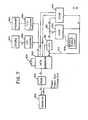
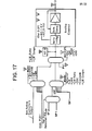
- the keyboard display comprises a microprocessor 900, a latch 910, a random access memory (RAM) 920, a memory protection circuit 925, a read only memory (ROM) 930, I/O expanders 960, 980, a display 970 and a keyboard 990.
- the key board display comprises a communication multiplexer 940 and a connector 955.
- the microprocessor 900 may for example, be an 8039/8049 Intel microprocessor with a six Mhz clock crystal 905.
- Latch 910 is a 3732type octal D-type flip-flop which controls an address bus 912 in response to a signal from microprocessor 900.
- Address bus 91 2 provides eight bits of address to RAM 920 and ROM 930. Data from these units is returned to microprocessor 900 on an eight bit parallel data bus 914.
- RAM 920 is a pair of 5101-type 256 X 4 bit CMOS memory chips connected together to provide 256 bytes of random access storage. Two control lines from microprocessor 900 control the operation of writing into and reading from these chips.
- RAM 920 permits data to be copied between the intelligent keyboard/display and an SLC instrument such as a controller or a recorder.
- the stored data is protected against power failure by a long-life battery in memory protection circuit 925.
- ROM 930 is four units of 2K X 8 bit memory such as a 2716-type read only memory. Each ROM unit is addressed by the eight address lines of bus 912 and three additional address lines. Four additional lines sslect the individual ROM chip.
- the operating program for the intelligent keyboar d /display is stored in ROM 930. This program, scans keyboard 990, debounces the signal from a key and generates a code for the particular key depressed.
- look-up tables one for each different type of SLC instrument, are stored in ROM so that the code is interpreted in accordance with the instrument to which the keyboard/display is connected.
- the program also provides for the display of one or more characters at specified positions on display and controls required to send and receive serial data through connector 955.
- I/O expanders 960, 980 are 8243-type coder/ decoders capable of producing an output signal on one of sixteen lines on the decoded side of the expander in accordance with a four bit signal received on the coded side and capable of producing a four bit coded output signal on the coded side of the expander in response to a signal received on one of sixteen lines on the uncoded side of the expander.
- I/O expander 960 provides an interface to display 970; and I/O expander 980 provides an interface to keyboard 990.
- Display 970 is an eight character alphanumeric display which illustratively is supplied by a pair of Litronics DL1414 display chips.
- Keyboard 990 is a nine row by five column Texas Instruments keyboard.
- Communications multiplexer 940 may like communication multiplexers 140, 400 and 740 of the controller board, front panel board and auxiliary board,be a 75138- type multiplexer.
- Connector 955 is adapted to mate with connectors 255, 415 and 755 shown in Figures 2, 3 and 5.
- the intelligent keyboard/display of Figure 7 provides a means of reading data from and entering data into any one of the controller board, the front nanal board and the auxiliary board and could also be connected in a similar manner to another device such as a recorder.
- the keyboard/ display provides a means for displaying many of the numerous variables which are generated by the microprocessors on those boards or are received as inputs at those boards.
- the keyboard/display provides a means for selecting many different operating options of the programs stored on these boards as well as a means for overriding certain input signals.
- the keyboard/display has the ability to alter the configuration of the individual controllers selected by three of panel switches 320.
- the keyboard/display also has the capability of reading and storing the operating configuration of the controller. The configuration can then be read out from the keyboard/display, and it may be arranged for it to be printed by a suitable recorder.
- the ksyboard/displet is first initialized by plugging it into the unit.
- the keyboard/display will then determine what instrument and model it has been plugged into and will display some unique identifier such as LMR for an L-M-R controller, RECORDR for a recorder, etc.
- the keyboard/display will then enter an operating mode in which the keys of keyboard 990 have functions that are particularly suited for interaction with the control instrument to which it is connected.
- the keyboard has the labels shown in Table 3. The function of each of these keys is explained in Table 4
- the READ function of the keyboard/display is used.
- One, two or three keystrokes are used to identify the desired variable.
- a "lower case” key requires one keystroke. Examples are SP for setpoint and OUT for the output.
- "Upper case” keys require the SHIFT key to be pressed before the variable keystroke.
- An example is SHIFT DEV for deviation.
- some variables are subscripted; these require a number to be entered. Examples of these are D02 for the second digital output and SHIFT AI 6 for analog input number 6.
- an underline symbol - is displayed to prompt the user. if no number is entered, 1 is automatically used. Otherwise, the appropriatenumber key should be depressed.
- the display will display the keystroke. This, hereinafter, is called the ID or identifier.
- the next 6 characters (nnnnnn) may be numeric or alphanumeric depending on the variable. If numeric, the first character is either blank or a minus sign. The next 5 characters are 4 digits plus a decimal point. Numeric values may range from-.0001 to 9999. If alphabetic, up to 4 characters are displayed. Examples are G/M,PSIG, AMPS,V. If the item is an option, an alphanumericrstringup to seven characters may be displayed. Examples are 0-5V, LINOP 1, V ** 1/2.
- the last character , I is a special identifier used with numeric values.
- the following table describes the various identifiers:
- the final key associated with the read function is ID, This key will display the identifier of the currently displayed variable on the display. For example, if a local setpoint value is displayed and 10 is pressed, the display will change to LSP.
- the ENTER function is used to change various values, options, etc. in the SLC instruments. To enter a new value, the variable must first be read and displayed as above.
- step 2 or 3 If a mistake is made in step 2 or 3, CLEAR is pressed and a new value is entered. The variable is not changed until ENTER is pressed and the equal sign is displayed. If varification is desired, CLEAR is pressed to clear the display, followed by READ to display the current value.
- Some variables are read-only because they cannot be changed from the intelligent keyboard. Examples are analog inputs and calculated variables.
- the read-only items continue to be displayed if CLEAR is pressed. This informs the user that the variable is read-only.
- the intelligent keyboard also has a slewing feature which performs 2 distinct functions: changing numeric variables, and selecting non-numeric variables. Two keys, raise, ⁇ , and lower, ⁇ . are used for slewing
- any changable numeric value may be slewed.
- the advantage of slewing over entry of a new value is that a large bump is prevented.
- the rate at which the variabbs is slewed depends on the type of variable, its current value and the activity on the communication bus of the system. By pressing the SHIFT key along with raise, ⁇ , or lower, ⁇ , the variable will slew at 15 times the slow slew rate.
- the rate is approximately 1%/second for a slow slew, and 15%/second for fast.
- the slow slew is a fixed value approximately 1% of full scale per second.
- a fixed increment is added to the value as a function of the value:
- the slew rates that have been quoted assume that no other communication is occurring. If there is other communication (such as updating the controller's bar graph display) the slew rates will slow down to approximately 1/2 or 1/3 of the stated rated.
- Certain keys refer to features and options that can have several possible states.
- the slew keys are used to get the desired option into the display. Next SHIFT and ENTER are pressed. After a short delay, the question mark will disappear to indicate that the setting has been selected.
- the analog output #3 of the controller may be used for output, setpoint (SP), process variable (PV) or be turned off. If, say, it is set for output but PV is desired, the user may press the key sequence shown in Table 5.
- a key labelled NEXT is provided to allow stepping through all of the variables, constants and options in an SLC instrument's data base. This function will reduce the number of keystrokes necessary for the user to view all of the data.
- NEXT When NEXT is pressed, the identifier for the next item is displayed. Typically, the user will alternately press NEXT and READ to view all of the data. When the last item is reached, the NEXT function will stop operating. Table 6 indicates the display that can be generated by repeated use of the NEXT key.
- the intelligent keyboard/diplay units that have been described may be associated with a recorder in a way that will be described later, but the foregoing elements can be configured in numerous ways to define any one of the seven types of controllers enumerated earlier and to provide numerous options and features. Some of these features Will be apparent from Table 7 which lists the analog and digital inputs and outputs to the seven types of controller and from the discussion of Figures 8-17 which provide a software block diagram for the controller.
- Block diagrams depicting the software that is used by the controller board to control a process are set forth in Figs. 8-17.
- a number in a triangle is used to indicate the source of certain control inputs or to provide comments about the signal.
- the number 1 indicates that the source is the intelligent keyboard/display or the serial communication module.
- the key on the keyboard of the keyboard-display which controls the input is identified in brackets.
- the number 2 indicates that the signal is derived from switch panel 320 on front panel board 20.
- the number 3 indicates that the input is derived from one or more of panel switches 210 on control board 10.
- the number 4 indicates that the signal is one of the analog or digital inputs or outputs to the system.
- the number 5 indicates that the signal in question is a read only signal that is readable by the keyboard/ display using the key indicated in brackets. Where a choice is to be made between two or more inputs in a software routine, the choice is indicated by a large vertical oval. Appended to a line at the top or bottom of the oval is a legend which indicates the key and/or signal which selects each one of the inputs to the oval. The legends are in the same order as the signal inputs which they select.
- All active inputs are read and processed at the controller's loop processing rate, which may be up to ten times per second. Inputs are normally processed regardless of whether they will actually be used by the controller but improved control response may be possible if unused inputs are made inactive.
- Fig. 8 depicts the software processing performed by one of the analog inputs to the controller. The same processing is performed on the other five.
- Each analog input goes through a 1.5 Hz hardware filter to eliminate electrical noise in input protection and filtering circuit 140.
- the signal is digitized by a high speed successive approximation method having a resolution of twelve bits.
- Keyboard entries IN OP 1 through IN OP 6 of keyboard/display 12 specify an input signal range of either 0-5V or 1-5V for each of the six analog inputs.
- the input signal is then ratioed so that the value passed on to the next software processing block has a range of 0.000 to 1.000, corresponding to 0% and 100%.
- Each analog input can be subjected to one of four linearization algorithms selected by use of the keyboard inputs LIN OP 1 through LIN OP 6. These algorithms are standard zero nd scale linearization, square root linearization, thr e-halves linearization, and five-halves linearization. Next, each linearized analog input may be filtered by an 0.15 Hz filter as specified by keyboard entries FLTR 1 through 6. Six analog input signals are then made available to the other operating blocks of the controller.
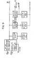
- the process variable can be the signal from analog input AI1 or it can be modified as shown in Fig. 9 to be a composite of that signal and the signal from analog input AI3.
- the key PVOP can be used to select any one of the following signals as the process variable.
- the resulting signal is then tested for several alarm limits. These include a 0.5% change of value, and a value greater than and lower than a limit entered from the keyboard/display by keys PV ALM 1 and PV ALM 2, and a deviation from a set point which can be specified by the key DEV ALM.
- the process variable is then applied to the PID block (Fig. 13) for calculation of the output.
- the local setpoint (LSP) is provided as follows for operation in the LOCAL and MANUAL modes.
- the local setpoint In the LOCAL mode, the local setpoint is used as the controller's setpoint.
- the local setpoint In the MANUAL (MAN) mode, the local setpoint will track the process variable if setpoint tracking is specified by operation of the TRK OP key on the keyboard/display.
- the software block diagram which produces the local setpoint signal is set forth in Fig. 10.
- the controller's setpoint in the REMOTE-AUTO mode is the linearized analog input AI2LIN. This value is clamped by a remote setpoint lower limit (RSP LL) and a remote setpoint upper limit (RSP HL) entered by the keyboard/display.
- RSP LL remote setpoint lower limit
- RSSP HL remote setpoint upper limit
- the local setpoint will track the remote setpoint if setpoint tracking is specified by the key SP TRK. Otherwise, the local setpoint will remain unchanged.
- the setpoint is supplied by the computer when in the COMPUTER-AUTO mode.
- Three algorithms shown in the bottom left-hand side of Fig. 11 are available for generating the setpoint.
- the setpoint is updated by a signal from the computer that is applied to the controller via linearized analog input AI2 LIN when digital input (DI1) is true for a specified period of time and the computer fail input (DI3) is inactive.
- the setpoint is updated by a sample and hold routine.
- the setpoint is raised 0.1% of full scale for each DI1 pulse received and lowered 0.1% of full scale for each DI2 pulse received, provided the computer fail input is inactive.
- the set point is updated with the value contained within an "Update SP" message received through the serial communication module 16. Any one of these three algorithms may be selected by the key SRC OP on the keyboard/ display. If setpoint tracking is specified, the setpoint will track the computer setpoint.
- the controller's setpoint may be specified to be either the local setpoint or the linearized analog input AI2 IN, the choice being made by the key L/R SP on the keyboard/ display. If the controller is in the AUTO mode with an analog input and setpoint tracking specified, the local setpoint will track the remote setpoint; otherwise it will remain unchanged. In the MANUAL and DDC modes, the local setpoint will track the process variable if setpoint tracking is specified.
- the controller's setpoint is the product of the linearized analog input AI2 LIN and either the local ratio (L RAT) or another analog input (AI3LIN) called the remote ratio (R RAT) as shown in the upper left hand corner of Fig. 11.
- L RAT local ratio
- R RAT remote ratio
- the choice of multipliers is selected by the key L/R RAT on the keyboard/display.
- the local ratio will track the ratioed setpoint if setpoint tracking is specified. Otherwise the local setpoint will remain unchanged.
- the primary controller's setpoint is the local setpoint (LSPl).
- LSPl local setpoint
- this local setpoint will track process variable PV1 if setpoint tracking is specified. Otherwise, the setpoint will remain unchanged.
- the primary controller's final output OUT 1 is the setpoint of the secondary controller.
- the secondary controller's local setpoint LSP 2 is used as the secondary controller's set point.
- process variable PV 2 is used as a secondary controller's set point. If setpoint tracking is specified in the MANUAL mode, LSP2 will track PV 2.
- the first controller's setpoint may be either a local setpoint or a remote setpoint, the choice being made by the key L/R SP 1. If it is the remote setpoint, the signal is provided by the linearized analog input AI2 LIN. In the MANUAL mode, LSP 1 will track the process variable PV1 if setpoint tracking is specified. Otherwise, the local setpoint will remain unchanged. In all other modes, if the controller's setpoint is the analog input and setpoint tracking is specified, then the local setpoint will track the remote setpoint provided by the analog input. Controller 2 is configured in the same manner as controller 1.
- L/R SP 2 on the keyboard display specifies whether local setpoint LSP 2 or the linearized clamped analog input AI5 LIN is to be used as its setpoint. In the MANUAL mode, LSP 2 will track process variable PV2 if setpoint tracking is specified. There is no provision to permit LSP 2 to track a remote setpoint.
- Feedforward control can be used to control processes with long reponse characteristics where the response of the process to a known load disturbance is of a predictable nature.
- a secondary process variable AI3 or FF signal is utilized along with the primary process variable (PV) to improve the overall control action.
- FF is a measured parameter whose value changes almost instantly with a load disturbance
- FV is a parameter whose value is controlled at the setpoint level and is not immediately affected by the change.
- the feedforward input remains constant, no Feedforward action will occur.
- the module will produce an FF output signal of zero. Should a sudden load disturbance occur, FF out will go above or below zero, thus permitting feedforward action to bias the controller's output.
- the time delay before the correction is applied and the correction's magnitude, sense (i.e. direct/reverse) and duration are all configurable.
- AI3 will become stable and unchanging and normal controller action is resumed. In this manner, the effects of the disturbance are anticipated by AI3, thereby reducing the time required for PV to stabilize.
- the feedforward processing is depicted in Fig. 12.
- Fig. 13 illustrates the calculation of the PID algorithm.
- the algorithm is a "velocity" PID algorithm with built-in anti-reset windup protection and rate limiting.
- the algorithm is of the "interacting" type but permits integral-only action.
- up to three sets of PID tuning parameters, KP, KI and KD can be selected for use as an advanced tuning feature in the PID algorithm. These sets are selected in accordance with one of the following independent variables: process variable PV1, the deviation between the setpoint and the process variablie, the absolute value of the deviation, the valve position feedback, an analog input supplied through AI5 LIN or two external digital inputs. The particular value used is selected by the TV OP key on the keyboard/display.
- the three sets of tuning parameters may be entered through the keyboard/display using the KP, KI and KD keys. Three breakpoints determining the ranges over which these constants are used may be entered by the TV BKPT key.
- a step and slope option may be selected for KI, KP, and KD by the I OP, P OP, D OP keys, respectively.
- tuning variable is a digital input
- step option applies. If both digital inputs are high, then KP1, KI1 and KD1 are selected. If the first digital input is high and the second low, then KP2, KI2 and KD2 are selected. If the first digital input is low, KP3, KI3 and KD 3 are selected. Otherwise, for the step option the PID tuning parameters are selected in accordance with the following:
- the slope option allows the tuning parameter to be a linear function of the input variable.
- the PID values, KP, KI and KD are selected by the slope option in accordance with the following criteria:
- the cascade and auto selector controllers have a second PID controller shown in Fig. 14.
- This controller uses the same algorithms as the controllers of Fig. 13 and contains the same features except for advanced tuning.
- the controller uses the PID2 constants KP2, KI2 and KD2 which can be entered through the keyboard/display.
- KP2, KI2 and KD2 which can be entered through the keyboard/display.
- the process variable is AI2 LIN and the setpoint can be any one of a number of setpoints depending on the mode of operation of the controller.
- the process variable is AI4 LIN and the setpoint is either LSP2 or is provided through AI5 LIN.
- the output of the PID algorithm is processed by the block diagram of Fig. 15. In the MANUAL Mode, the output signal is provided by OUTMAN. Otherwise for all controllers except DDC, CASCADE and AUTO SELECTOR, block 15B selects the output of the PID algorithm as the output of the controller subject to mode selection and overrides.
- Block 15C provides signal selection for the DDC controller.
- the output from PID1 is the controller's output.
- the output value is supplied directly by a computer.
- Block 15D describes output selection for the cascade controller. Unless the mode is PRI AUTO, the controller's output is the output from PID2. In the PRI AUTO mode the controller's output is that from PID1.
- Blocks 15E and 15F control the output for the auto selector controller.
- the output is the higher or lower of the output of the two controllers, the choice being specified by the key H/L SEL on the keyboard/display.
- PID1 supplies the output; and in the CONTR2 mode, PID2 supplies the output, as indicated by block 15G.
- High and low overrides can be configured by the keyboard entry H OVR OP and L OVR OP.
- the output is the minimum of the calculated output and the analog input AI5LIN.
- the output is the maximum of the calculated output and the analog input AI4 LIN.
- the output signal is also subject to output clamping specified by the keyboard/display keys OUT HL and OUT LL.
- a dead band control can be specified by the key DB.
- the output of the controller will not change unless the calculated output differs from the current output by the dead band amount.
- Use of dead band control reduces valve wear by eliminating valve movements that are smaller than the dead band amount.
- the dead band may be set at any value between 0 and 100%.
- Fig. 16 depicts the hardware/software mechanism for ramping the controller's output OUT 1 from its existing value to the target output value calculated by the controller and for maintaining that target value.
- the functions within this block execute at a much faster rate than the normal 100 ms loop update period.
- Analog sample and hold circuit 200 of Fig. 2 is refreshed every 12.5 ms, or 8 times per loop update. For each refresh, 1/8 of the difference between the old and new output values is sent to the sample and hold circuit so that the output appears to ramp to the new value rather than making one discrete step of the entire change.
- the ramp control shown in Fig. 16 inherently limits the ramp rate to 100% per second, a rate that can be followed by most actuators.
- DI4 is the INHB R signal in the CMPTR and DDC Controllers.
- DI1 is the INHB R signal in all other Controllers.
- the INHB R signal is normally configured in conjunction with the Stepper and Pulse Duration Output options. It may also be configured with the analog output option to provide a "digital" high override.
- DI5 is the INHB L signal in the CMPTR and DDC models.
- D12 is the INHB L signal in all other models.
- the INHB L signal is normally configured in conjunction with the Stepper and Pulse Duration Output options. It may also be configured with the analog output option to provide a "digital" low override.
- the controller's actual output is read through multiplexer 150 to allow drift-compensation and offset correction of the analog output.
- the sample/hold analog output circuitry is refreshed every 12.5 milliseconds.
- the output value is adjusted as required over the next loop update period to ramp the output to the new target value.
- One of switches 210 specifies the full scale output range to be either 0-5 Volts (0-20mA) or 1-5 Volts (4-20 mA).
- phase A and phase B digital outputs are sequenced over the next loop processing period as required to step the Stepper Actuator to the new target angular position.
- Maximum step rate is 1 step every 5 milliseconds or 200 steps per second (10 second full scale response).
- pulse duration control is selected and if a RAISE is required, digital outputs OUT 1 and OUT 2 are set to the 0 and 1 states. If a LOWER is required, OUT 1 and OUT 2 are set to the 1 and 0 states. If no change is required, the outputs are both set to the 1 state.
- Actuator full scale response time is 10 sec; and Pulse duration resolution is 10 milliseconds.
- An auxiliary output A03 is also available as shown in Fig. 17.
- One of hardware switches 210 sets the range of this output to either 0-5 volts or 1-5 volts.
- the sample & hold circuitry is refreshed every 12 milliseconds and drift compensation is performed.
- A03 is not ramped.
- One of three variables OUT, SET POINT and PV1 can be selected to drive the auxiliary output by the A03 OP key.
- A03 OPT OUT for the AUTO SELECTOR controller, AO 3 is the unclamped output of either controller 1 or controller 2, whichever was not selected as the main output OUT1.
- A03 is the unclamped output of controller 1.
- A03 OP SP for the AUTO SELECTOR controller
- A03 is the setpoint of the controller whose output was selected as the main output.
- the clamped remote setpoint will be sent out; and for all other models, the local setpoint LSP is used.
- process variable PV1 is the output. PV1 may be a calculated value such as the average of two analog inputs.
- Figure 18 is a block diagram illustrating a recorder which may be used with an intelligent keyboard/display to print alphanumeric or graphic displays.
- the recorder comprises a micorprocessor 1000, a latch 1010, a random access memory (RAM)1020, a memory protection circuit 1025, a read only memory (ROM) 1030, a serial communication module 1035, an input protection and filtering circuit 1040, an analog multiplexer 1050, I/O expanders 1060, 1070, 1080, a digital to analog converter 1090, a comparator 1095, a digital display 1100 a chart motor driver 1110, a thermal printing head 1120 communications multiplexer 1140 and connector 115.
- RAM random access memory
- ROM read only memory
- serial communication module 1035 an input protection and filtering circuit 1040
- an analog multiplexer 1050 I/O expanders 1060, 1070, 1080
- a digital to analog converter 1090 1090
- a comparator 1095 a digital display 1100 a chart motor driver
- microprocessor 1000 is an Intel 8039/8040 microprocessor.
- Latch 1010 is a 373-type octal D-type flip-flop which controls an address bus 1012 in response to a signal from microprocessor 1000.
- Address bus 1012 provides eight bits of address to RAM 1020, ROM 1030 and the communication module 1035. Data from these units is returned to microprocessor 1000 on an eight bit parallel data bus 1014.
- RAM 1020 is a pair of 5101-type 256 X 4 bit CMOS memory chips connected together to provide 256 bytes of random access storage. Two control lines from microprocessor 1000 control the operation of writing into and reading from these chips.
- RAM 1020 is used for temporary storage of data that is to be printed by the recorder and configuration data.
- ROM 1030 is three units 2K X 8 bit memory such as a 2716-type read only memory. Each ROM unit is addressed additional address lines. Two additional lines plus control logic (not shown) select the individual ROM chip.
- the operating program for the recorder is stored in ROM 1030.
- Multiplexer 1050 illustratively is a 4051-type one-out-of-eight multiplexer whose output is selected by three of the lines from I/O expander 1060.
- the analog output of multiplexer 1050 is converted to a digital signal by means of twelve bit digital-to-analog converter 1090, comparator 1095 and a standard analog-to-digital programming routine which is executed by microprocessor 1000.
- Digital signals may also be supplied to the recorder by the communication module which is similar to the module 16 shown in Figure 1.
- I/O expanders 1060, 1070, 1080 are connected to microprocessor 1000 via data bus 1016 and select lines 1018.
- I/O expander 1070 provides for signal outputs to digital display 1100 and chart motor drive 1110.
- I/O expander 1080 provides for signal outputs to thermal printing head 1120.
- Communication multiplexer 1140 is a 75138-type multiplexer which is used to multiplex incoming and outgoing clock and data signals.
- Connector 1155 mates with connector 955 (see Figure 7) of the intelligent keyboard/display and provides for the transmission of clock and data signals to and from the intelligent keyboard/display.
- Digital display 1100 is illustrated in greater detail in Figure 19.
- the digital display comprises a seven segment decoder 1210, a decoder 1220,drivers 1230, 1240 and a display 1250 capable of displaying four groups of four digits each.
- each digit is represented by a seven segment display; and a decimal point can be located to the left of any one of the four digits in a row.
- Decoder 1220 has four signal input lines and sixteen signal output lines. In response to a four bit parallel input signal, it strobes one of the sixteen different digits of display 1250 so as to illuminate the segments of the seven , segment display of that digit in accordance with the signals from seven segment decoder 1210.
- the seven segment decoder 1210 has four inputs which specify the ten numeric digit plus special symbols.
- the seven outputs of decoder 1210 specify which of the seven segments of the display of a given character are illuminated.
- the eighth line which is applied directly to driver 1230 controls the display of the decimal point. In order to display a..minus sign, the central horizontal bar of the seven segment display can be controlled from the microprocessor.
- Seven segment decoder 1210 may be a 47-type BCD-to-7-segment decoder and decoder 1220 a 4514 decoder.
- the seven segment drivers 1230 may be a pair of 2907-type drivers and the digit select drivers 1240 may be a pair of 2813-type drivers.
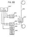
- the thermal printing head 1120 is depicted in greater detail in Figure 20. As shown therein, the printing head comprises a set of latch/drivers 1310, a set of latch/ drivers 1320, a pulse width control 1330, a thermal head temperature sensor 1340 and a thermal printing head 1350.
- the thermal printing head may, for example, be a commercial device such as the DM 69414 printing head manufactured by Gulton Industries, Inc. of Metuchen, New Jersey. This printing head contains a single continuous row of printing elements spaced so as to print one hundred dots per inch on a strip that is slightly more than four inches wide.
- the printing head uses a total of sixty-nine address lines and nine strobed lines to deliver to the individual printing elements sufficient current to print visible indicia on a tecording medium 1360, such as a thermal paper.
- Latch/drivers 1310 consist of an array of latches and drivers suitable for driving the sixty-nine address lines.
- Latch/predrivers 1320 provide an array of latches and drivers suitable for driving the strobe lines.
- the intensity, or gray scale, of the print may be controlled by means of thermal head temperature sensor 1340 and pulse width control 1330.
- the intensity of the printed indicia will decrease with decreasing ambient temperature of the thermal head. To compensate for this, it has been found advantageous to adjust the length of the electrical pulse used for printing.
- the intelligent keyboard/display is plugged into the recorder by mating connectors 955 ( Figure 7) and 1155 ( Figure 8). The keyboard/display will then determine that it has been connected to a recorder and will display RECORDR on display 970. At the same time the keyboard/display selects the recorder operating program which defines the keys of keyboard 990 as shown in Table 8. The keyboard sequence and display sequence in response thereto and explanatory comments relating to these keys are set forth in Table 9
- keyboard/display and recorder may be put in the hard copy printout of data stored in random access memory 920 of the keyboard/display.
- Data may be stored in RAM 920 from any single loop control instrument to which the keyboard/display is connected. The data may then be read from the keyboard display into RAM 1020 of the recorder.
- the contents of RAM 1020 may then be printed by thermal printing head 1120 on an appropriate recording medium 1360.
- the keys of the keyboard/display can also be configured as an alphanumeric keyboard for entry of text onto the hard copy output of the recorder.
- the intelligent keyboard/display provides a versatile device but can be used for reading data from and entering data into different computer controlled instruments.
- the keyboard/display provides a means for reconfiguring these instruments by selecting various options, a means for determining the particular options selected and a means for storing the configuration of a parricular instrument.
- the keyboard/display may be used to provide hard copy output.
Landscapes
- Engineering & Computer Science (AREA)
- Human Computer Interaction (AREA)
- Manufacturing & Machinery (AREA)
- Physics & Mathematics (AREA)
- General Physics & Mathematics (AREA)
- Automation & Control Theory (AREA)
- Control By Computers (AREA)
- Feedback Control In General (AREA)
Applications Claiming Priority (4)
| Application Number | Priority Date | Filing Date | Title |
|---|---|---|---|
| US06/227,969 US4431988A (en) | 1981-01-23 | 1981-01-23 | Microprocessor-based keyboard/display unit for configuring control instruments |
| US227970 | 1981-01-23 | ||
| US06/227,970 US4418381A (en) | 1981-01-23 | 1981-01-23 | Single loop control system |
| US227969 | 1981-01-23 |
Publications (1)
| Publication Number | Publication Date |
|---|---|
| EP0057541A1 true EP0057541A1 (de) | 1982-08-11 |
Family
ID=26921926
Family Applications (1)
| Application Number | Title | Priority Date | Filing Date |
|---|---|---|---|
| EP82300338A Withdrawn EP0057541A1 (de) | 1981-01-23 | 1982-01-22 | Einzelschleifensteuerungssysteme |
Country Status (1)
| Country | Link |
|---|---|
| EP (1) | EP0057541A1 (de) |
Cited By (1)
| Publication number | Priority date | Publication date | Assignee | Title |
|---|---|---|---|---|
| US20140094937A1 (en) * | 2010-11-16 | 2014-04-03 | Artur Kuprijanov | Control Device |
-
1982
- 1982-01-22 EP EP82300338A patent/EP0057541A1/de not_active Withdrawn
Non-Patent Citations (2)
| Title |
|---|
| Control and Instrumentation, Volume 7, No. 9, October 1975 London (GB) WOOD: "De-Centralisation of Intelligence - the Key to Low Cost Control?" pages 30-33 * pages 30, left-hand column, lines 35-40; page 33, middle column, lines 13-20 and 36-40 and right-hand column, lines 29-60 * * |
| Regelungstechnnische Praxis, Volume 22, No. 3, March 1980 Munchen (DE) SENDLER: "Ein Fehlertolerierende Reglerstation auf der Basis eines Busorientierten Multi-Mikrorechner-Systems", pages 73-81 * pages 77, left-hand column, line 28 to right-hand column, line 20; figure 4 * * |
Cited By (2)
| Publication number | Priority date | Publication date | Assignee | Title |
|---|---|---|---|---|
| US20140094937A1 (en) * | 2010-11-16 | 2014-04-03 | Artur Kuprijanov | Control Device |
| US9823629B2 (en) * | 2010-11-16 | 2017-11-21 | Siemens Aktiengesellschaft | Dual loop control system with interactive automatic tracking mode |
Similar Documents
| Publication | Publication Date | Title |
|---|---|---|
| US4418381A (en) | Single loop control system | |
| US4431988A (en) | Microprocessor-based keyboard/display unit for configuring control instruments | |
| US4064395A (en) | Machine control system employing a programmable machine function controller | |
| KR920018546A (ko) | 플랜트 콤포넌트 제어 시스템을 위한 작업자 계면 | |
| US4521845A (en) | Numerical control device | |
| CN102759940A (zh) | 全功能型螺栓拧紧轴控制器 | |
| US4542464A (en) | Autopilot system | |
| US4551664A (en) | Velocity-position servo with improved gain control | |
| EP0057541A1 (de) | Einzelschleifensteuerungssysteme | |
| CN202583775U (zh) | 全功能型螺栓拧紧轴控制器 | |
| EP0198248A2 (de) | Steuereinheit für einen von einem Frequenzumrichter gespeisten Drehstrommotorantrieb | |
| US4744022A (en) | Programmable control apparatus including an absolute position transducer | |
| US4856924A (en) | Printer | |
| DE3827383C2 (de) | ||
| US4835676A (en) | Programmable control apparatus including an absolute position transducer | |
| US5224031A (en) | Signal transfer system of programmable controller | |
| SU702379A1 (ru) | Система управлени технологическим процессом | |
| EP0251565A3 (de) | Autopilot-Regelungseinrichtung für Schiffsfahrzeuge | |
| SU1113807A1 (ru) | Устройство централизованного контрол и управлени технологическими агрегатами | |
| JPS58132804A (ja) | 調節計 | |
| SU723496A1 (ru) | Регул тор | |
| KR950002090Y1 (ko) | 데이터등재 및 표시장치 | |
| CN2163398Y (zh) | 工艺美术图形设计编程控制器 | |
| Tipton et al. | The MTIRA computer numerical control (CNC) system | |
| SU1629715A1 (ru) | Система автоматического управлени химико-технологическим процессом |
Legal Events
| Date | Code | Title | Description |
|---|---|---|---|
| PUAI | Public reference made under article 153(3) epc to a published international application that has entered the european phase |
Free format text: ORIGINAL CODE: 0009012 |
|
| AK | Designated contracting states |
Designated state(s): AT BE CH DE FR GB IT LU NL SE |
|
| 17P | Request for examination filed |
Effective date: 19830209 |
|
| STAA | Information on the status of an ep patent application or granted ep patent |
Free format text: STATUS: THE APPLICATION IS DEEMED TO BE WITHDRAWN |
|
| 18D | Application deemed to be withdrawn |
Effective date: 19840502 |
|
| RIN1 | Information on inventor provided before grant (corrected) |
Inventor name: O'LOUGHLIN, THOMAS M. Inventor name: MOLUSIS, ANTHONY J. |