EP0057601A2 - Winde - Google Patents
Winde Download PDFInfo
- Publication number
- EP0057601A2 EP0057601A2 EP82300491A EP82300491A EP0057601A2 EP 0057601 A2 EP0057601 A2 EP 0057601A2 EP 82300491 A EP82300491 A EP 82300491A EP 82300491 A EP82300491 A EP 82300491A EP 0057601 A2 EP0057601 A2 EP 0057601A2
- Authority
- EP
- European Patent Office
- Prior art keywords
- winch
- rope
- arrangement
- transmission
- load
- Prior art date
- Legal status (The legal status is an assumption and is not a legal conclusion. Google has not performed a legal analysis and makes no representation as to the accuracy of the status listed.)
- Ceased
Links
Images
Classifications
-
- B—PERFORMING OPERATIONS; TRANSPORTING
- B66—HOISTING; LIFTING; HAULING
- B66D—CAPSTANS; WINCHES; TACKLES, e.g. PULLEY BLOCKS; HOISTS
- B66D1/00—Rope, cable, or chain winding mechanisms; Capstans
- B66D1/60—Rope, cable, or chain winding mechanisms; Capstans adapted for special purposes
Definitions
- This invention concerns improvements in and relating to winches, and more especially to winches of the kind that may be subject to wide fluctuations in load during operation of the winch drive.
- the winch arrangement may become subject to wide variations in load due to a lack of coordination between the operation of the winch drive and the operation of the braking system of the vehicle.
- This problem is especially acute in the case of a winch to be applied to aircraft which may need to be hauled rapidly into a hanger or other enclosure, since the efficiency of the braking system of an aircraft is such that very substantial and sudden loads can be placed on the winch rope, causing possible damage to the aircraft and/or the winch itself.
- a winch arrangement comprising a drive motor; a winch drum assembly coupled to said drive motor by means of a transmission incorporating a reduction gear, said transmission including a component of relatively high inertia, whereby in the event of sudden cease of drive from the drive motor the transmission can run on to drive the winch drum assembly and take up possible slack in the winch rope; rope guide means for guiding rope from a load to the winch drum along an indirect path; and shock absorbing buffer means associated with said guide means and arranged, upon sudden increase in the load in the winch rope above a predetermined limit, to allow deflection of the winch rope and to absorb the load placed on the rope due to the inertia of the system.
- the above-mentioned transmission includes a non-return device arranged to prevent the winch drum from rotating in the reverse direction under the load placed on the winch rope, following stoppage of the transmission and the said transmission incorporates a releasable clutch means to enable manual unreeling of the winch rope prior to operation of the winch.
- the said clutch means comprises an electromagnetically actuatable clutch
- the said winch drum is provided with an electromagnetically actuatable braking means
- a control circuit incorporating a first timing circuit for controlling release of said clutch means, and a second timing circuit for release of said brake means, the said timing circuits being arranged for consecutive operation in timed relationship such that following release of said clutch means, the said brake means remains applied for a predetermined period of time sufficient to permit relaxation of tension in the winch rope.
- the said brake and clutch operating circuits may incorporate a safety interlock with the operating circuit for the winch drive motor,,to prevent operation thereof when the motor is running.
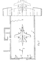
- FIG. 1 there is illustrated one possible site installation of a winch arrangement in accordance with the invention, which comprises an aircraft hanger or bomb shelter illustrated generally at 1.
- the purpose of the winch arrangement is to permit winching of an aircraft 2 into the position illustrated within the shelter, from a position outside the shelter and illustrated in broken lines.
- the winch drive assembly is thus located at the position indicated diagrammatically at 3, and the winch rope passes from the position 3, initially along a path 4, to a pulley 5 from which it passes along a path 6 to an attachment point at the rear of the aircraft.
- the pulley 5 is preferably releasable from its anchorage to enable location in any one of a plurality of desired mounting positions indicated at 5A.
- Manual operation of the winch drive may be effected from a local winch control panel indicated at 7, or, optionally, from a remote portable push button station indicated at 8 and connected to the control circuit by way of a flying cable 9.
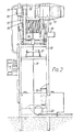
- the winch assembly comprises a fixed, vertical stand 10 at the upper end of which is mounted a winch drive motor 11 incorporating an eddy current, overload coupling 12 of generally known type.
- the output shaft from the eddy current coupling 12 is connected by way of a reduction gear 32 and an electromagnetically actuatable clutch device 13 to a drive pinion 14 which is in permanent meshing engagement with a driving gearwheel 15.
- the gearwheel 15 is fixed to a winch drum 17.
- the winch drum 17 is provided with an electromagnetically actuatable brake device 16. It is also coupled to a geared limit switch device 18 for indicating the limit positions of the fully wound and fully unwound winch rope 19.
- the winch rope 19 passes, via a rope layering device 20 and a safety switch 21 for sensing slackness in the rope, to a guide pulley 22, over which the winch rope 19 is deflected from its downward vertical path to a horizontal path corresponding to the path 4 illustrated in Figure 1.
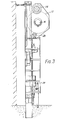
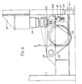
- the pulley 22 is mounted to the stand 1 by way of a lever arm 23 pivoted in a fixed mounting 24 secured to the frame 1.
- a free end 23A'of the lever arm 23 is normally located in a rest position defined by an adjusting bolt 25 threaded in a mounting 26, also secured to the stand 1, and locked in position by means of a lock nut 27.
- the end 23A of the lever 23 thus abuts against the free end of the adjusting bolt 25.
- a roller 28 which is in engagement with the lower end of a shock absorbing buffer 29, which is of known type and secured to the stand 1 by means of a fixed mounting 30.
- the rating of the buffer 29 is such that under normal operating conditions of the winch arrangement the buffer remains in its extended position, but that upon excessive tension or overload occurring in the winch rope, the buffer will allow deflection of the lever arm 23 in an upward direction, as indicated in broken lines, thus allowing limited yielding of the winch rope in a direction towards the winch drum during such overload conditions.
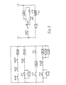
- Figure 5 is a simplified circuit diagram of the operating circuit of the winch arrangement. It will be seen that the circuit of Figure 5 comprises two, electrically isolated portions, that on the left-hand side of Figure 5 comprising a control circuit, and that on the right-hand side of Figure 5 comprising an actuating circuit for the electromagnetic brake and clutch means referred to above.
- the positions of the switch and relay contacts illustrated in Figure 5 correspond to a condition of the winch assembly wherein the winch rope is in a position intermediate its extreme wound and unwound positions, the rope is slack, and the control circuit is in an idle condition.
- the winch rope must first be unwound to a starting position in order to enable attachment to the aircraft.
- the reduction gear 32 referred to above with reference to Figures 2 and 3 incorporates a non-return device preventing reverse rotation of transmission from the eddy current coupling 12.
- the electromagnetic clutch 13 must be released.
- Relay R1 thus becomes energised, and, at contact R1/1, completes a self-holding circuit to maintain energisation of the relay R1 upon release of the push button P.O. Simultaneously, relay contact R1/3 is changed over, so that the actuation circuit of an energising winding B1 of the electromagnetic brake 16 is broken, due to the open condition of the slack rope sensing switch 21, indicated diagrammatically at S.R. in Figure 5.
- the electromagnetic brake 16 is of a fail safe construction, that is to say that the brake is held in the released condition when the winding B1 is energised, and is applied when the circuit of winding B1 is broken.
- a timer, or slow to operate relay, T1 which is connected in parallel with relay R1, becomes energised after a delay of, for example, 1 second.
- the timer T1 breaks the circuit of an energising winding C1 of the electromagnetic clutch 13.
- the clutch 13 is a dog-clutch which is held in engagement upon energisation of the winding C1, and therefore the opening of contact T1/1 causes the clutch to be disengaged.
- the transmission between the coupling 12 and the winch drum 17 is thus broken to enable reverse movement of the winch drum 17, but initially the latter is retained against this movement by the braking device 16.
- T2 becomes energised and, at its contact T2/1, breaks the circuit to the relay R2.
- Relay contact R2/1 is thus restored to its idle condition preparing an energizing path to the brake winding B1.
- the brake winding B1 will now become energised and the electromagnetic brake 16 will thus be released to enable unwinding of the winch cable.
- a limit switch indicated diagrammatically at L.S. in Figure 5, will become opened, breaking the energising circuit of the brake winding B1 and causing the brake to be re-applied.
- the fully extended winch rope may now be attached to the aircraft to be towed into the hanger.
- Relay R3 thus becomes energised, and, at relay contact R3/2, breaks the holding circuit to relay R1, timer T1 and timer T2.
- Contact R3/1 of relay R3 also prepared a current path to a relay circuit for actuating the winch drive motor and indicated diagrammatically at M. R.
- the winch drive motor 11 may, in known manner, be protected against overloading by means of the eddy current coupling 12 which serves as a torque limiting device, in the event of very sudden overloads upon the winch arrangement, for example by sudden application of the aircraft brakes whilst the winch drive is running, the overloading will initially appear as a shock upon the winch drum and its associated transmission. Owing to its own inertia, very sudden overloading will not be sensed at the eddy current coupling 12 until damage has already been caused to the winch drive and/or the aircraft, due to the tendency of the eddy current coupling 12 to run on under its own inertia. Overloading in the latter circumstances is compensated for by means of the pulley 22 and the associated buffer arrangement.
- the lever arm 23 is coupled, in a manner not shown in the drawing, to an overload sensing microswitch, indicated diagrammatically at O.L. in Figure 5, whereby the microswitch is closed upon deflection of the lever 23.
- an overload sensing microswitch indicated diagrammatically at O.L. in Figure 5, whereby the microswitch is closed upon deflection of the lever 23.
- the relay R2 becomes energised to effect stoppage of the drive motor 11 by way of relay contact-R2/2 which breaks the energising circuit of the motor relay M.R.
- the above-described action of the timers T1 and T2 is essential in order to ensure that the winch drum 17 is initially held in a braked condition following release of the clutch 13, braking being maintained for a period of time sufficient to allow relaxation of tension in the winch rope without danger or possible faulty operation due to sudden return movement of the winch drum 17.
Landscapes
- Engineering & Computer Science (AREA)
- Mechanical Engineering (AREA)
- Braking Arrangements (AREA)
- Control And Safety Of Cranes (AREA)
- Dynamo-Electric Clutches, Dynamo-Electric Brakes (AREA)
Applications Claiming Priority (2)
| Application Number | Priority Date | Filing Date | Title |
|---|---|---|---|
| GB8102735 | 1981-01-29 | ||
| GB8102735A GB2092087B (en) | 1981-01-29 | 1981-01-29 | Winching arrangements |
Publications (2)
| Publication Number | Publication Date |
|---|---|
| EP0057601A2 true EP0057601A2 (de) | 1982-08-11 |
| EP0057601A3 EP0057601A3 (de) | 1982-10-27 |
Family
ID=10519321
Family Applications (1)
| Application Number | Title | Priority Date | Filing Date |
|---|---|---|---|
| EP82300491A Ceased EP0057601A3 (de) | 1981-01-29 | 1982-01-29 | Winde |
Country Status (3)
| Country | Link |
|---|---|
| US (1) | US4448395A (de) |
| EP (1) | EP0057601A3 (de) |
| GB (1) | GB2092087B (de) |
Cited By (3)
| Publication number | Priority date | Publication date | Assignee | Title |
|---|---|---|---|---|
| WO2010084340A3 (en) * | 2009-01-21 | 2011-03-17 | Jacobus Hendrik Cilliers | Portable winch assembly |
| CN102285604A (zh) * | 2011-05-31 | 2011-12-21 | 太原重工股份有限公司 | 具有超载保护装置的单联卷筒起升机构 |
| EP2921447A3 (de) * | 2014-03-20 | 2015-10-28 | Robert Bosch Gmbh | Stationäres Hubwerk mit Dämpfer und hydraulischer Dämpfer |
Families Citing this family (3)
| Publication number | Priority date | Publication date | Assignee | Title |
|---|---|---|---|---|
| US7984894B1 (en) | 2007-06-22 | 2011-07-26 | Chauza Roger N | Electrical clutch engagement/disengagement apparatus |
| US9099148B2 (en) * | 2012-03-30 | 2015-08-04 | Oracle International Corporation | Magnetic Z-directional clutch |
| US10207905B2 (en) | 2015-02-05 | 2019-02-19 | Schlumberger Technology Corporation | Control system for winch and capstan |
Family Cites Families (11)
| Publication number | Priority date | Publication date | Assignee | Title |
|---|---|---|---|---|
| AT17505B (de) * | 1903-09-17 | 1904-09-10 | Windhoff Rheiner Maschf | Abwickelvorrichtung für Drahtseile von Windetrommeln, besonders für Rangierwinden. |
| US2244830A (en) * | 1936-03-10 | 1941-06-10 | Waterbury Tool Co | Power transmission |
| US2249947A (en) * | 1936-05-02 | 1941-07-22 | Waterbury Tool Co | Power transmission |
| DE668346C (de) * | 1936-11-12 | 1938-12-01 | Maschf Augsburg Nuernberg Ag | Windwerk mit Spulvorrichtung zur Verhuetung von Schlaffseil |
| US2303847A (en) * | 1939-08-01 | 1942-12-01 | American Eng Co Ltd | Towing machine |
| DE804593C (de) * | 1949-11-27 | 1951-04-26 | Maschf Augsburg Nuernberg Ag | Stripperkran |
| US2723833A (en) * | 1953-05-08 | 1955-11-15 | Burfeind Henry Frank | No-power holding, low-inertia, winch system |
| GB1206975A (en) * | 1967-08-05 | 1970-09-30 | T T Boughton And Sons Ltd | Improvements in or relating to winching systems |
| US3612486A (en) * | 1969-10-17 | 1971-10-12 | Nat Defence Canada | Vertical load transfer |
| FR2209709B1 (de) * | 1972-12-11 | 1976-01-30 | Etat Francais Fr | |
| DE2933879C2 (de) * | 1979-08-22 | 1986-05-22 | Messerschmitt-Bölkow-Blohm GmbH, 8012 Ottobrunn | Fanghakenkupplung für Flugzeuge |
-
1981
- 1981-01-29 GB GB8102735A patent/GB2092087B/en not_active Expired
-
1982
- 1982-01-18 US US06/340,037 patent/US4448395A/en not_active Expired - Fee Related
- 1982-01-29 EP EP82300491A patent/EP0057601A3/de not_active Ceased
Cited By (4)
| Publication number | Priority date | Publication date | Assignee | Title |
|---|---|---|---|---|
| WO2010084340A3 (en) * | 2009-01-21 | 2011-03-17 | Jacobus Hendrik Cilliers | Portable winch assembly |
| US8550438B2 (en) | 2009-01-21 | 2013-10-08 | Jacobus Hendrik Cilliers | Portable winch assembly |
| CN102285604A (zh) * | 2011-05-31 | 2011-12-21 | 太原重工股份有限公司 | 具有超载保护装置的单联卷筒起升机构 |
| EP2921447A3 (de) * | 2014-03-20 | 2015-10-28 | Robert Bosch Gmbh | Stationäres Hubwerk mit Dämpfer und hydraulischer Dämpfer |
Also Published As
| Publication number | Publication date |
|---|---|
| US4448395A (en) | 1984-05-15 |
| GB2092087A (en) | 1982-08-11 |
| GB2092087B (en) | 1985-12-04 |
| EP0057601A3 (de) | 1982-10-27 |
Similar Documents
| Publication | Publication Date | Title |
|---|---|---|
| US4147197A (en) | Fire door and operator therefor | |
| US5323877A (en) | Device for the triggering of safety equipments of a lift plant | |
| US5238200A (en) | Power driven winding device with spool axially movable to engage a clutch | |
| AU2003304530A1 (en) | Remotely resettable ropeless emergency stopping device for an elevator | |
| US5020640A (en) | Elevator brake | |
| US4448395A (en) | Improvements in and relating to winches | |
| EP0433922B1 (de) | Bremsmechanismus für Regalförderzeug | |
| JPS5841275B2 (ja) | ケンインクドウソウチ | |
| US3469657A (en) | Automatic emergency relevelling device for lifts | |
| US4368770A (en) | Door, preferably for industrial buildings | |
| US4364453A (en) | Safety installation for elevators | |
| US3917019A (en) | Vehicle and safety device for same | |
| WO2001087763A1 (en) | Improved driving device for the traction of cables or chains | |
| US1999936A (en) | Lifting device | |
| US2254910A (en) | Safety hoist | |
| CN115874595B (zh) | 一种船闸闸门防撞装置及防撞方法 | |
| US3695396A (en) | Safety brake unit for a mine cage | |
| JP3289160B2 (ja) | シャッターの自動閉鎖装置 | |
| US20020194944A1 (en) | Remote brake release with clutch | |
| US3598202A (en) | Elevator door control | |
| CA3138020C (en) | Impactor apparatus operated from rotorcraft | |
| EP0655410B1 (de) | Automatische Sicherheitstestvorrichtung für hydraulische Aufzüge | |
| EP0345901B1 (de) | Verfahren und Vorrichtung zum Regeln der Drehung eines Elementes um eine Welle durch eine Schlingfeder | |
| CN220886604U (zh) | 一种建筑施工电梯牵引绳断绳保护安全机构 | |
| GB2285482A (en) | Flexible doors |
Legal Events
| Date | Code | Title | Description |
|---|---|---|---|
| PUAI | Public reference made under article 153(3) epc to a published international application that has entered the european phase |
Free format text: ORIGINAL CODE: 0009012 |
|
| AK | Designated contracting states |
Designated state(s): DE IT NL |
|
| PUAL | Search report despatched |
Free format text: ORIGINAL CODE: 0009013 |
|
| AK | Designated contracting states |
Designated state(s): DE IT NL |
|
| 17P | Request for examination filed |
Effective date: 19830309 |
|
| STAA | Information on the status of an ep patent application or granted ep patent |
Free format text: STATUS: THE APPLICATION HAS BEEN REFUSED |
|
| 18R | Application refused |
Effective date: 19860621 |
|
| RIN1 | Information on inventor provided before grant (corrected) |
Inventor name: PURDY, WILLIAM CHARLES |