EP0057622A2 - Hydraulische lineare Zugvorrichtung, die zwei selbstklemmende Backen aufweist, welche abwechselnd das axial geführte lasttragende Seil festklemmen - Google Patents
Hydraulische lineare Zugvorrichtung, die zwei selbstklemmende Backen aufweist, welche abwechselnd das axial geführte lasttragende Seil festklemmen Download PDFInfo
- Publication number
- EP0057622A2 EP0057622A2 EP82400061A EP82400061A EP0057622A2 EP 0057622 A2 EP0057622 A2 EP 0057622A2 EP 82400061 A EP82400061 A EP 82400061A EP 82400061 A EP82400061 A EP 82400061A EP 0057622 A2 EP0057622 A2 EP 0057622A2
- Authority
- EP
- European Patent Office
- Prior art keywords
- cylinders
- clamping
- winch
- jaws
- hydraulic
- Prior art date
- Legal status (The legal status is an assumption and is not a legal conclusion. Google has not performed a legal analysis and makes no representation as to the accuracy of the status listed.)
- Granted
Links
- 238000009432 framing Methods 0.000 claims abstract description 3
- 230000000903 blocking effect Effects 0.000 claims description 7
- 230000005540 biological transmission Effects 0.000 description 1
- 238000006073 displacement reaction Methods 0.000 description 1
- 230000000694 effects Effects 0.000 description 1
- 238000012986 modification Methods 0.000 description 1
- 230000004048 modification Effects 0.000 description 1
- 238000004904 shortening Methods 0.000 description 1
- 230000001502 supplementing effect Effects 0.000 description 1
- 230000001360 synchronised effect Effects 0.000 description 1
Images

Classifications
-
- F—MECHANICAL ENGINEERING; LIGHTING; HEATING; WEAPONS; BLASTING
- F16—ENGINEERING ELEMENTS AND UNITS; GENERAL MEASURES FOR PRODUCING AND MAINTAINING EFFECTIVE FUNCTIONING OF MACHINES OR INSTALLATIONS; THERMAL INSULATION IN GENERAL
- F16G—BELTS, CABLES, OR ROPES, PREDOMINANTLY USED FOR DRIVING PURPOSES; CHAINS; FITTINGS PREDOMINANTLY USED THEREFOR
- F16G11/00—Means for fastening cables or ropes to one another or to other objects; Caps or sleeves for fixing on cables or ropes
- F16G11/04—Means for fastening cables or ropes to one another or to other objects; Caps or sleeves for fixing on cables or ropes with wedging action, e.g. friction clamps
- F16G11/044—Means for fastening cables or ropes to one another or to other objects; Caps or sleeves for fixing on cables or ropes with wedging action, e.g. friction clamps friction clamps deforming the cable, wire, rope or cord
- F16G11/048—Means for fastening cables or ropes to one another or to other objects; Caps or sleeves for fixing on cables or ropes with wedging action, e.g. friction clamps friction clamps deforming the cable, wire, rope or cord by moving a surface into the cable
-
- B—PERFORMING OPERATIONS; TRANSPORTING
- B66—HOISTING; LIFTING; HAULING
- B66D—CAPSTANS; WINCHES; TACKLES, e.g. PULLEY BLOCKS; HOISTS
- B66D3/00—Portable or mobile lifting or hauling appliances
- B66D3/006—Power actuated devices operating on ropes, cables, or chains for hauling in a mainly horizontal direction
-
- E—FIXED CONSTRUCTIONS
- E04—BUILDING
- E04G—SCAFFOLDING; FORMS; SHUTTERING; BUILDING IMPLEMENTS OR AIDS, OR THEIR USE; HANDLING BUILDING MATERIALS ON THE SITE; REPAIRING, BREAKING-UP OR OTHER WORK ON EXISTING BUILDINGS
- E04G21/00—Preparing, conveying, or working-up building materials or building elements in situ; Other devices or measures for constructional work
- E04G21/12—Mounting of reinforcing inserts; Prestressing
- E04G21/121—Construction of stressing jacks
Definitions
- the present invention relates to a hydraulic linear winch comprising a pair of self-clamping jaws alternately clamping the axial cable carrying the load.
- French Patent No. 1,394,309 describes such a hydraulic linear winch comprising a frame on which two double-acting hydraulic cylinders are symmetrically fixed, framing a pair of self-tightening jaws capable of alternately blocking the axial cable at the end of which the load is fixed, these two self-tightening jaws being aligned on the axis of symmetry of the winch, one being integral in translation, along said axis of the winch, with the cylinders of these double-acting hydraulic cylinders, and the other of their pistons.
- the self-clamping jaws proposed in this patent each consist of two bars provided with semi-cylindrical bearing surfaces which can pivot in openings made in pivoting connecting rods.
- the present invention relates to such a winch characterized in that its self-clamping jaws are constituted by cable tightening corners comprising cylinders interposed between the corresponding oblique faces of their external and internal elements, and in that these cylinders are truncated by two planes parallel, symmetrical with respect to their axes, and perpendicular to said pblical faces.
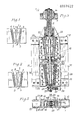
- the cable clamping corner 1 shown in FIG. 1 comprises cylinders with parallel axes 2 interposed between the oblique faces 3 of. its fixed elements 5, and 4 of its mobile elements 6, in the internal faces 7 of which grooves 8 are hollowed out in which the cable 1 can slide or be blocked; it is understood that, when the movable elements 6 of the clamping wedge are biased towards the bottom of the figure, they transmit pressure to the fixed elements 5, by means of their oblique faces 3 and 4, and cylinders with interposed parallel axes 2, which cause a tightening of the grooves 8 of their internal faces 7 on the cable 1 which is blocked there.
- these cylinders 2 have been replaced by cylinders 2a, each of which is truncated by two planes parallel to its axis, perpendicular to the oblique surfaces 3 and 4, and symmetrical with respect to that -this ; the width of these truncated cylinders is approximately half the diameter of the cylinders 2 of the conventional wedge shown in FIG. 1, which allows, for the same bearing surface and, consequently, for the transmission of the same effort, to reduce the length by half, or, possibly, to reduce the number by half.
- the hydraulic linear cylinder shown in FIGS. 3 to 5 includes such cable tightening corners 1, aligned one above the other; it is suspended from a beam 9 by means of a ball joint 10, and it comprises a fixed frame 11, on which the fixed external elements 12 of the upper clamping corner are fixed, comprising truncated cylinders 13 between the parallel oblique faces of its fixed elements 12 and of its movable interior elements 14.
- the pivoting of these truncated cylinders 13, during the relative displacement of the elements of the clamping wedge are made integral by pairs of pins 15, engaged in corresponding holes of bars 16 , parallel to the oblique bearing faces of the exterior 12 and interior 14 elements of the clamping wedge.
- Means are also provided such that, for raising the load, corresponding to the shortening of the jacks, the lower clamping wedge 19 is locked on the cable 1 and the upper clamping wedge 18 released, when one of the the other of the two clamping corners, and vice versa, while, for the descent of the load, corresponding to the elongation of the jacks, the lower clamping wedge 19 is locked on the cable and the upper clamping wedge 18 released, and vice versa.
- two friction plates 20 are symmetrically interposed, on either side of the cable 1, between the lateral faces of the movable interior elements 14 and 22 of the upper clamping corners 18 and lower 19, and the flanges 23 and 24 of these clamping corners; these friction plates 20 are tightened elastically against said lateral faces by springs.
- the lower clamping wedge 19 can therefore move away freely from the upper clamping wedge 18; the latter, trapped on cable 1, keeps it fixed, and the load which is attached to it suspended at the level previously reached, until the lower clamping wedge 19 arrives in its extreme position corresponding to the maximum elongation of the double-acting cylinders 17 shown in FIG. 4.
- the double-acting cylinders 17 are operated in the opposite direction, so as to shorten them, and by consequently to bring the lower clamping wedge 19 closer to the upper clamping wedge 18, the external elements 21 of the lower clamping wedge 19 are pulled upwards and exert pressure on the internal elements 22 of said lower clamping wedge 19 which lock on cable 1; simultaneously, the ascent of the internal elements 22 of the lower clamping wedge 19 causes, by means of the friction plates 20, an upward thrust on the internal elements 14 of the upper clamping wedge 18 which is released.
- the cable 1 can therefore slide freely in the upper clamping corner 18, and the lower clamping corner 19, pulled upwards by the two double-acting cylinders 17, drives the cable 1 on which it is locked, as well as the load suspended from this cable, until it reaches the initial position shown in Figure 3; this cycle can then be repeated as many times as necessary to gradually lift the load, each time from a height corresponding to the maximum elongation of the double-acting cylinders, until it has reached the desired level.
- the hydraulic linear winch shown further comprises hydraulic blocking cylinders 25 and 26 which make it possible to block in the inactive position the movable internal elements 14 and 22 of the upper 18 and lower clamping corners 19. They are used, as will be explained below. below when lowering the load and their action, synchronized with the alternating movements of the pistons of the double-acting cylinders, can be controlled by electrical circuits not shown which can automatically open or close the pistons of the double-acting cylinders, when they alternative trips.
- the double-acting cylinders 17 are then operated in order to lengthen them; the lower clamping corner 19 drives down the cable 1 on which it is blocked, and the load suspended from this cable, said cable sliding freely in the upper clamping corner 18 blocked in the loosened position by the locking cylinders 25.
- the lower clamping wedge 19 moves freely by sliding on the cable 1, since it is locked in the released position, and the upper clamping wedge 18, which is in the clamping position, keeps the cable 1 and the load it carries at the level previously reached; the friction of the friction plates 20 on the interior elements 14 of the upper clamping wedge 18 is obviously insufficient to lift them and loosen the upper clamping wedge 18.
- the internal elements 22 of the lower clamping corner 19 are released by the locking cylinders 26; they are immediately driven downwards by the friction plates 20; the rise of the lower clamping wedge 19 is first slowed down; the lower clamping wedge 19 then blocks on the cable 1 which it maintains, with the load it carries, at the lower level previously reached.
- the internal elements 14 of the upper clamping block 18 had firstly been slightly raised, at the end of the upward stroke of the lower clamping wedge 19, by the friction plates 20, and had immediately been locked in the loosened position by the corresponding locking cylinder 25.
- a safety device can be provided for each of the two clamping corners, upper 18 and lower 19; it may consist of a pair of jaws 27, suspended by rods 28 from the movable interior elements 14 and 22 of these clamping corners, and springs 29, such as a stack of Belleville washers, tending to clamp the two jaws on the cable 1.
- This safety device also offers the advantage of supplementing the action of the friction plates to carry out the sliding downwards or upwards in a timely manner and, consequently, the blocking or unblocking of the internal elements. 14 and 22 of the upper and / or lower corners.
- Hydraulic cylinders 30 enable these jaws 27 to be released when the interior elements 14 and 22 must be kept locked in the inactive position by the locking cylinders 25 and 26; these jacks 30 can therefore be controlled directly by the reciprocating movements of the pistons of the double-acting jacks 17 using the same electrical circuits as those of the hydraulic jacks 25 and 26.
Landscapes
- Engineering & Computer Science (AREA)
- Mechanical Engineering (AREA)
- General Engineering & Computer Science (AREA)
- Architecture (AREA)
- Civil Engineering (AREA)
- Structural Engineering (AREA)
- Load-Engaging Elements For Cranes (AREA)
- Forwarding And Storing Of Filamentary Material (AREA)
- Clamps And Clips (AREA)
- Laying Of Electric Cables Or Lines Outside (AREA)
- Electric Cable Installation (AREA)
Priority Applications (1)
| Application Number | Priority Date | Filing Date | Title |
|---|---|---|---|
| AT82400061T ATE10481T1 (de) | 1981-01-19 | 1982-01-14 | Hydraulische lineare zugvorrichtung, die zwei selbstklemmende backen aufweist, welche abwechselnd das axial gefuehrte lasttragende seil festklemmen. |
Applications Claiming Priority (2)
| Application Number | Priority Date | Filing Date | Title |
|---|---|---|---|
| FR8100891A FR2498169B1 (fr) | 1981-01-19 | 1981-01-19 | Coin de serrage de cable et treuil lineaire hydraulique utilisant de tels coins de serrage |
| FR8100891 | 1981-01-19 |
Publications (3)
| Publication Number | Publication Date |
|---|---|
| EP0057622A2 true EP0057622A2 (de) | 1982-08-11 |
| EP0057622A3 EP0057622A3 (en) | 1982-08-25 |
| EP0057622B1 EP0057622B1 (de) | 1984-11-28 |
Family
ID=9254284
Family Applications (1)
| Application Number | Title | Priority Date | Filing Date |
|---|---|---|---|
| EP82400061A Expired EP0057622B1 (de) | 1981-01-19 | 1982-01-14 | Hydraulische lineare Zugvorrichtung, die zwei selbstklemmende Backen aufweist, welche abwechselnd das axial geführte lasttragende Seil festklemmen |
Country Status (6)
| Country | Link |
|---|---|
| US (1) | US4427180A (de) |
| EP (1) | EP0057622B1 (de) |
| JP (1) | JPS57166268A (de) |
| AT (1) | ATE10481T1 (de) |
| DE (1) | DE3261308D1 (de) |
| FR (1) | FR2498169B1 (de) |
Cited By (14)
| Publication number | Priority date | Publication date | Assignee | Title |
|---|---|---|---|---|
| FR2543123A1 (fr) * | 1983-03-22 | 1984-09-28 | Ruhrkohle Ag | Procede et dispositif pour faire avancer un cable pendant, dont les cables d'extraction sont bloques dans des installations d'extraction de puits a poulie motrice, a cable unique ou multiple |
| FR2554103A1 (fr) * | 1983-10-27 | 1985-05-03 | Kley France | Bloc de traction pour treuil lineaire |
| GB2158030A (en) * | 1984-04-28 | 1985-11-06 | Psc Freyssinet Ltd | Cable lifting jack |
| US4569507A (en) * | 1984-11-27 | 1986-02-11 | Kley France | Traction block for linear winch |
| EP0179961A1 (de) * | 1984-10-31 | 1986-05-07 | KLEY-FRANCE, Société Anonyme dite: | Klemmbackenblöcke für Linearwinde |
| EP0177980A3 (en) * | 1984-10-06 | 1987-04-08 | Harumoto Iron Works Co., Ltd. | Apparatus for stretching, loosening, and fixing a wire member |
| EP0220968A1 (de) * | 1985-10-23 | 1987-05-06 | Cibeles International Inc. | Kontinuierlich arbeitende hydraulische Seilzugvorrichtung |
| EP0232634A1 (de) * | 1986-01-17 | 1987-08-19 | Cibeles International Inc. | Klemmblock mit durch Umkehrung der Zugkraft lösbaren Keilen für ein längliches Element, wie ein Seil oder eine Stange |
| US4838522A (en) * | 1988-02-01 | 1989-06-13 | Mcdermott International Inc. | Deepwater subsea lowering/lifting system |
| DE3490693C2 (de) * | 1984-04-24 | 1990-05-10 | Upravlenie Po Montazu, Demontazu I Remontu Gornosachtnogo Oborudovanija "Specsachtomontaz" Karagandinskogo Proizvodstvennogo Ob"Edinenija Po Dobyce Uglja "Karagandaugol'", Karaganda, Su | |
| US4951924A (en) * | 1988-02-01 | 1990-08-28 | Mcdermott International, Inc. | Deepwater subsea lowering/lifting system |
| EP0397270A1 (de) * | 1989-05-12 | 1990-11-14 | RIVA CALZONI S.p.A. | Linearwinde mit mehrfachen Zwingen mit programmierter Steuerung zur kontinuierlichen Bewegung des Zugkabels |
| WO2000032903A1 (en) * | 1998-11-18 | 2000-06-08 | Future Productions As | Supply system and method for changing wires in a riser tensioner system |
| US11479449B2 (en) * | 2017-02-13 | 2022-10-25 | Taiyuan University Of Technology | Vertical lifting device and method |
Families Citing this family (15)
| Publication number | Priority date | Publication date | Assignee | Title |
|---|---|---|---|---|
| DE3313199C2 (de) * | 1983-04-12 | 1987-05-14 | Fritz 5600 Wuppertal Stumpmeier | Klemmbackenanordnung für eine schrittweise arbeitende hydraulische Seilzugvorrichtung |
| WO1993016840A1 (en) * | 1992-02-28 | 1993-09-02 | Combustion Engineering, Inc. | O.d. gripper |
| WO1998030350A1 (en) | 1997-01-09 | 1998-07-16 | Robert Ward Carter | Device for trenchless replacement of underground pipe |
| CH694513A5 (de) * | 1999-04-01 | 2005-02-28 | Ingbuero Fuer Maschb Rikli Chr | Vorrichtung zum Befestigen, Spannen oder Ziehen eines dehnbaren Zugelementes, insbesondere eines Seiles. |
| US6761507B2 (en) * | 2001-09-04 | 2004-07-13 | Earth Tool Company, L.L.C. | Method and apparatus for replacement of underground pipe |
| ES2276576B2 (es) * | 2005-01-28 | 2008-02-16 | Sociedad Anonima De Preformados Metalicos | Maquina para tensado de cables conductores de lineas electricas aereas. |
| EP1976088A1 (de) * | 2007-03-29 | 2008-10-01 | Rex-Technologie Gmbh & Co. Kg | Vorrichtung zum Einführen von einer Einziehfeder |
| EP1976086A1 (de) * | 2007-03-29 | 2008-10-01 | Rex-Technologie Gmbh & Co. Kg | Vorrichtung zum Einführen von einer Einziehfeder |
| GB201001161D0 (en) * | 2010-01-25 | 2010-03-10 | Bamford Antony S | Underwater tubing workover |
| US8540458B2 (en) | 2011-06-14 | 2013-09-24 | Roodle, Inc. | Center hole ram cable puller |
| NL2007804C2 (nl) * | 2011-11-17 | 2013-05-21 | Roofsecurity Int Gmbh | Valbeveiligingssysteem voor een hellend dak. |
| CA2984243A1 (en) * | 2015-04-27 | 2016-11-03 | Richard V. Campbell | Advanced methods and designs for balancing a stranded termination assembly |
| GB2539672B (en) * | 2015-06-23 | 2019-02-20 | Alfred Cheyne Engineering Ltd | Linear winch assembly and method of use |
| GB2548921B (en) * | 2016-04-01 | 2021-08-11 | Mammoet Offshore Services Ltd | Winch |
| CN106939928A (zh) * | 2017-04-26 | 2017-07-11 | 无锡市新华起重工具有限公司 | 钢丝绳快速接头 |
Family Cites Families (19)
| Publication number | Priority date | Publication date | Assignee | Title |
|---|---|---|---|---|
| US1307653A (en) | 1919-06-24 | Supporting and hoisting mechanism | ||
| GB191026593A (en) * | 1910-11-16 | 1911-10-19 | Louis Sidney Rayner | Improvements in or connected with " Safety" Gripping Apparatus for Mine or Lift Cages or the like, and other Gripping purposes. |
| US1581459A (en) | 1924-07-11 | 1926-04-20 | Otis Elevator Co | Elevator safety appliance |
| US1581458A (en) * | 1924-07-11 | 1926-04-20 | Otis Elevator Co | Elevator safety appliance |
| FR639092A (fr) * | 1927-08-05 | 1928-06-13 | Stephanois Constr Meca | Attache à coins, à serrage proportionnel à la charge suspendue, pour câbles ronds métalliques |
| US2581052A (en) * | 1946-03-25 | 1952-01-01 | Mavor & Coulson Ltd | Haulage apparatus for mining machines |
| US2933275A (en) * | 1955-11-04 | 1960-04-19 | Wimmersperg Heinrich Ferdi Von | Extensible, telescoping legs for supports |
| FR1394809A (fr) * | 1964-02-04 | 1965-04-09 | Central De Gestion Et De Contr | Treuil hydraulique à mâchoires auto-serreuses |
| US3278158A (en) | 1964-08-06 | 1966-10-11 | Saldana Juan Angel | Lifting mechanism, actuating means therefor and slab anchoring means therefor |
| CH518771A (de) | 1970-05-30 | 1972-02-15 | Waldrich Werkzeugmasch | Ausrichtvorrichtung für Werkstücke auf Werkzeugmaschinentischen |
| US3762512A (en) * | 1971-10-29 | 1973-10-02 | Us Elevator Corp | Elevator rail grab safety apparatus |
| CH568870A5 (en) * | 1973-03-12 | 1975-11-14 | Eidgenoess Tech Hochschule | Brake system for ski lifts and cableways - has wedge shaped needle bearing mounted emergency brake |
| DE2352836C2 (de) * | 1973-10-22 | 1975-01-30 | Georg Mueller Kugellagerfabrik Kg, 8500 Nuernberg | Klemmvorrichtung |
| DE2502984A1 (de) * | 1974-01-30 | 1975-07-31 | Ahlgren Nils H | Schwerlast-hebezeug |
| FR2346588A1 (fr) | 1975-10-20 | 1977-10-28 | Pradon Jacques | Pince de serrage |
| SE395876B (sv) | 1975-12-18 | 1977-08-29 | Anderson Ind Ab Paul | Anordning vid tryckmediumdrivan kletterdomkrafter |
| FR2348405A1 (fr) * | 1976-04-13 | 1977-11-10 | Tractel Sa | Dispositif de liaison pour l'entrainement de machoires auto-serreuses |
| US4277051A (en) | 1978-04-24 | 1981-07-07 | Marine Engineering Company, C. A. | Tilt-up/jack-up off-shore drilling apparatus and method |
| JPS55161786A (en) * | 1979-05-31 | 1980-12-16 | Mitsubishi Heavy Ind Ltd | Device for pulling heavy body |
-
1981
- 1981-01-19 FR FR8100891A patent/FR2498169B1/fr not_active Expired
-
1982
- 1982-01-13 US US06/339,164 patent/US4427180A/en not_active Expired - Fee Related
- 1982-01-14 AT AT82400061T patent/ATE10481T1/de active
- 1982-01-14 EP EP82400061A patent/EP0057622B1/de not_active Expired
- 1982-01-14 DE DE8282400061T patent/DE3261308D1/de not_active Expired
- 1982-01-19 JP JP57006735A patent/JPS57166268A/ja active Granted
Cited By (14)
| Publication number | Priority date | Publication date | Assignee | Title |
|---|---|---|---|---|
| FR2543123A1 (fr) * | 1983-03-22 | 1984-09-28 | Ruhrkohle Ag | Procede et dispositif pour faire avancer un cable pendant, dont les cables d'extraction sont bloques dans des installations d'extraction de puits a poulie motrice, a cable unique ou multiple |
| FR2554103A1 (fr) * | 1983-10-27 | 1985-05-03 | Kley France | Bloc de traction pour treuil lineaire |
| DE3490693C2 (de) * | 1984-04-24 | 1990-05-10 | Upravlenie Po Montazu, Demontazu I Remontu Gornosachtnogo Oborudovanija "Specsachtomontaz" Karagandinskogo Proizvodstvennogo Ob"Edinenija Po Dobyce Uglja "Karagandaugol'", Karaganda, Su | |
| GB2158030A (en) * | 1984-04-28 | 1985-11-06 | Psc Freyssinet Ltd | Cable lifting jack |
| EP0177980A3 (en) * | 1984-10-06 | 1987-04-08 | Harumoto Iron Works Co., Ltd. | Apparatus for stretching, loosening, and fixing a wire member |
| EP0179961A1 (de) * | 1984-10-31 | 1986-05-07 | KLEY-FRANCE, Société Anonyme dite: | Klemmbackenblöcke für Linearwinde |
| US4569507A (en) * | 1984-11-27 | 1986-02-11 | Kley France | Traction block for linear winch |
| EP0220968A1 (de) * | 1985-10-23 | 1987-05-06 | Cibeles International Inc. | Kontinuierlich arbeitende hydraulische Seilzugvorrichtung |
| EP0232634A1 (de) * | 1986-01-17 | 1987-08-19 | Cibeles International Inc. | Klemmblock mit durch Umkehrung der Zugkraft lösbaren Keilen für ein längliches Element, wie ein Seil oder eine Stange |
| US4838522A (en) * | 1988-02-01 | 1989-06-13 | Mcdermott International Inc. | Deepwater subsea lowering/lifting system |
| US4951924A (en) * | 1988-02-01 | 1990-08-28 | Mcdermott International, Inc. | Deepwater subsea lowering/lifting system |
| EP0397270A1 (de) * | 1989-05-12 | 1990-11-14 | RIVA CALZONI S.p.A. | Linearwinde mit mehrfachen Zwingen mit programmierter Steuerung zur kontinuierlichen Bewegung des Zugkabels |
| WO2000032903A1 (en) * | 1998-11-18 | 2000-06-08 | Future Productions As | Supply system and method for changing wires in a riser tensioner system |
| US11479449B2 (en) * | 2017-02-13 | 2022-10-25 | Taiyuan University Of Technology | Vertical lifting device and method |
Also Published As
| Publication number | Publication date |
|---|---|
| DE3261308D1 (en) | 1985-01-10 |
| ATE10481T1 (de) | 1984-12-15 |
| JPS6344664B2 (de) | 1988-09-06 |
| EP0057622A3 (en) | 1982-08-25 |
| US4427180A (en) | 1984-01-24 |
| FR2498169A1 (fr) | 1982-07-23 |
| JPS57166268A (en) | 1982-10-13 |
| EP0057622B1 (de) | 1984-11-28 |
| FR2498169B1 (fr) | 1985-06-28 |
Similar Documents
| Publication | Publication Date | Title |
|---|---|---|
| EP0057622B1 (de) | Hydraulische lineare Zugvorrichtung, die zwei selbstklemmende Backen aufweist, welche abwechselnd das axial geführte lasttragende Seil festklemmen | |
| EP0964102B1 (de) | Vorrichtung zum Transport und zur Installation des Decks einer Ölplatform im Meer | |
| EP3146131B1 (de) | Montagesystem und verfahren zur montage eines turms einer windkraftanlage | |
| FR2853891A1 (fr) | Dispositif d'assemblage demontable des elements de fleche d'une grue a tour | |
| BE1005112A5 (fr) | Installation de parking. | |
| WO1996000359A1 (fr) | Dispositif de pose de conduites flexibles a partir d'un support flottant | |
| WO1985003095A1 (fr) | Appareil mobile pour l'enfoncement dans le sol, par percussion, d'objects divers | |
| CA2056247C (fr) | Dispositif a ruban metallique articule, notamment pour le deplacement de charges lourdes | |
| FR2802504A1 (fr) | Dispositif ameliore d'equilibrage d'un navire notamment en roulis | |
| FR2556329A1 (fr) | Procede et dispositif pour tirer pas a pas les cables d'extraction d'une installation d'extraction d'un puits de mine | |
| FR2507506A1 (fr) | Laminoir continu a cages croisees pour la production de tubes sans soudure | |
| EP0469212A1 (de) | Vorrichtung für die vertikale Versetzung eines Bettes in eine Tragkonstruktion | |
| EP0054477B1 (de) | Antriebseinrichtung mit Zylindern zur Erzeugung der kontinuierlichen Bewegung eines länglichen Gegenstandes in Richtung seiner Achse und/oder zum Bewegen eines Elementes längs diesem Gegenstand | |
| FR2646151A1 (fr) | Bloc de serrage a machoires auto-serreuses, notamment pour treuil hydraulique lineaire | |
| FR2543123A1 (fr) | Procede et dispositif pour faire avancer un cable pendant, dont les cables d'extraction sont bloques dans des installations d'extraction de puits a poulie motrice, a cable unique ou multiple | |
| EP0071507B1 (de) | Vorrichtung zum Kanten von Giesstafeln für Betonpaneele | |
| FR2780441A3 (fr) | Equipement de forage pour percer des trous dans le sol | |
| FR2514275A1 (fr) | Machine de moulage avec fixation automatique des outillages | |
| FR2823029A1 (fr) | Pince motorisee pour le bridage d'elements allonges | |
| FR2594427A1 (fr) | Bras pour grue | |
| CH260697A (fr) | Appareil de traction et de levage. | |
| FR2512878A1 (fr) | Verin de puits supporte sur une structure de montage de table rotative | |
| FR3039530A1 (fr) | Dispositif d'elevation | |
| EP0227546A2 (de) | Vorrichtungen zum Spannen von Zugelementen vor der Verankerung | |
| FR2473932A1 (fr) | Plateau d'usinage basculant |
Legal Events
| Date | Code | Title | Description |
|---|---|---|---|
| PUAI | Public reference made under article 153(3) epc to a published international application that has entered the european phase |
Free format text: ORIGINAL CODE: 0009012 |
|
| PUAL | Search report despatched |
Free format text: ORIGINAL CODE: 0009013 |
|
| AK | Designated contracting states |
Designated state(s): AT BE CH DE GB IT LU NL SE |
|
| AK | Designated contracting states |
Designated state(s): AT BE CH DE GB IT LU NL SE |
|
| 17P | Request for examination filed |
Effective date: 19820722 |
|
| ITF | It: translation for a ep patent filed | ||
| GRAA | (expected) grant |
Free format text: ORIGINAL CODE: 0009210 |
|
| AK | Designated contracting states |
Designated state(s): AT BE CH DE GB IT LI LU NL SE |
|
| PG25 | Lapsed in a contracting state [announced via postgrant information from national office to epo] |
Ref country code: AT Effective date: 19841128 |
|
| REF | Corresponds to: |
Ref document number: 10481 Country of ref document: AT Date of ref document: 19841215 Kind code of ref document: T |
|
| REF | Corresponds to: |
Ref document number: 3261308 Country of ref document: DE Date of ref document: 19850110 |
|
| PLBE | No opposition filed within time limit |
Free format text: ORIGINAL CODE: 0009261 |
|
| STAA | Information on the status of an ep patent application or granted ep patent |
Free format text: STATUS: NO OPPOSITION FILED WITHIN TIME LIMIT |
|
| 26N | No opposition filed | ||
| ITTA | It: last paid annual fee | ||
| PGFP | Annual fee paid to national office [announced via postgrant information from national office to epo] |
Ref country code: SE Payment date: 19920108 Year of fee payment: 11 Ref country code: LU Payment date: 19920108 Year of fee payment: 11 |
|
| PGFP | Annual fee paid to national office [announced via postgrant information from national office to epo] |
Ref country code: GB Payment date: 19920110 Year of fee payment: 11 |
|
| PGFP | Annual fee paid to national office [announced via postgrant information from national office to epo] |
Ref country code: CH Payment date: 19920113 Year of fee payment: 11 |
|
| PGFP | Annual fee paid to national office [announced via postgrant information from national office to epo] |
Ref country code: DE Payment date: 19920128 Year of fee payment: 11 |
|
| PGFP | Annual fee paid to national office [announced via postgrant information from national office to epo] |
Ref country code: NL Payment date: 19920131 Year of fee payment: 11 |
|
| PGFP | Annual fee paid to national office [announced via postgrant information from national office to epo] |
Ref country code: BE Payment date: 19920204 Year of fee payment: 11 |
|
| EPTA | Lu: last paid annual fee | ||
| PG25 | Lapsed in a contracting state [announced via postgrant information from national office to epo] |
Ref country code: LU Free format text: LAPSE BECAUSE OF NON-PAYMENT OF DUE FEES Effective date: 19930114 Ref country code: GB Effective date: 19930114 |
|
| PG25 | Lapsed in a contracting state [announced via postgrant information from national office to epo] |
Ref country code: SE Effective date: 19930115 |
|
| PG25 | Lapsed in a contracting state [announced via postgrant information from national office to epo] |
Ref country code: LI Effective date: 19930131 Ref country code: CH Effective date: 19930131 Ref country code: BE Effective date: 19930131 |
|
| BERE | Be: lapsed |
Owner name: KLEY-FRANCE S.A. Effective date: 19930131 |
|
| PG25 | Lapsed in a contracting state [announced via postgrant information from national office to epo] |
Ref country code: NL Effective date: 19930801 |
|
| GBPC | Gb: european patent ceased through non-payment of renewal fee |
Effective date: 19930114 |
|
| NLV4 | Nl: lapsed or anulled due to non-payment of the annual fee | ||
| REG | Reference to a national code |
Ref country code: CH Ref legal event code: PL |
|
| PG25 | Lapsed in a contracting state [announced via postgrant information from national office to epo] |
Ref country code: DE Effective date: 19931001 |
|
| EUG | Se: european patent has lapsed |
Ref document number: 82400061.6 Effective date: 19930810 |