EP0057626A2 - Cible lumineuse prévue pour être utilisée en métrologie optique dans le domaine des mesures tridimensionnelles et méthode de mesure - Google Patents
Cible lumineuse prévue pour être utilisée en métrologie optique dans le domaine des mesures tridimensionnelles et méthode de mesure Download PDFInfo
- Publication number
- EP0057626A2 EP0057626A2 EP82400097A EP82400097A EP0057626A2 EP 0057626 A2 EP0057626 A2 EP 0057626A2 EP 82400097 A EP82400097 A EP 82400097A EP 82400097 A EP82400097 A EP 82400097A EP 0057626 A2 EP0057626 A2 EP 0057626A2
- Authority
- EP
- European Patent Office
- Prior art keywords
- elementary
- light source
- multidirectional light
- multidirectional
- sources
- Prior art date
- Legal status (The legal status is an assumption and is not a legal conclusion. Google has not performed a legal analysis and makes no representation as to the accuracy of the status listed.)
- Granted
Links
- 230000003287 optical effect Effects 0.000 title claims description 3
- 239000013307 optical fiber Substances 0.000 claims abstract description 9
- 239000004793 Polystyrene Substances 0.000 claims abstract description 3
- 229920002223 polystyrene Polymers 0.000 claims abstract description 3
- 239000002131 composite material Substances 0.000 claims description 7
- 239000000126 substance Substances 0.000 claims description 2
- 239000000835 fiber Substances 0.000 claims 2
- 239000002184 metal Substances 0.000 abstract description 3
- 238000000465 moulding Methods 0.000 abstract description 2
- 239000004033 plastic Substances 0.000 abstract description 2
- 238000005259 measurement Methods 0.000 description 4
- 230000005855 radiation Effects 0.000 description 3
- 239000007787 solid Substances 0.000 description 2
- 241001080024 Telles Species 0.000 description 1
- 230000005540 biological transmission Effects 0.000 description 1
- 238000001816 cooling Methods 0.000 description 1
- 239000004794 expanded polystyrene Substances 0.000 description 1
- 230000004907 flux Effects 0.000 description 1
- 238000004519 manufacturing process Methods 0.000 description 1
- 238000000691 measurement method Methods 0.000 description 1
- 230000002093 peripheral effect Effects 0.000 description 1
Images

Classifications
-
- G—PHYSICS
- G02—OPTICS
- G02B—OPTICAL ELEMENTS, SYSTEMS OR APPARATUS
- G02B6/00—Light guides; Structural details of arrangements comprising light guides and other optical elements, e.g. couplings
- G02B6/24—Coupling light guides
- G02B6/42—Coupling light guides with opto-electronic elements
- G02B6/4201—Packages, e.g. shape, construction, internal or external details
- G02B6/4202—Packages, e.g. shape, construction, internal or external details for coupling an active element with fibres without intermediate optical elements, e.g. fibres with plane ends, fibres with shaped ends, bundles
- G02B6/4203—Optical features
-
- G—PHYSICS
- G02—OPTICS
- G02B—OPTICAL ELEMENTS, SYSTEMS OR APPARATUS
- G02B6/00—Light guides; Structural details of arrangements comprising light guides and other optical elements, e.g. couplings
- G02B6/0001—Light guides; Structural details of arrangements comprising light guides and other optical elements, e.g. couplings specially adapted for lighting devices or systems
- G02B6/0005—Light guides; Structural details of arrangements comprising light guides and other optical elements, e.g. couplings specially adapted for lighting devices or systems the light guides being of the fibre type
- G02B6/0008—Light guides; Structural details of arrangements comprising light guides and other optical elements, e.g. couplings specially adapted for lighting devices or systems the light guides being of the fibre type the light being emitted at the end of the fibre
-
- G—PHYSICS
- G02—OPTICS
- G02B—OPTICAL ELEMENTS, SYSTEMS OR APPARATUS
- G02B6/00—Light guides; Structural details of arrangements comprising light guides and other optical elements, e.g. couplings
- G02B6/24—Coupling light guides
- G02B6/26—Optical coupling means
- G02B6/262—Optical details of coupling light into, or out of, or between fibre ends, e.g. special fibre end shapes or associated optical elements
Definitions
- the present invention relates to point radiant energy sources and more particularly to the creation of point light targets used in optical metrology in the field of three-dimensional measurements using theodolites.
- Any surface or volume that emits radiation constitutes a source of radiant energy.
- This source is considered as point source if its dimensions are very small compared to the distance which separates it from the receiver or from the observer.
- the present invention makes it possible to avoid these drawbacks.
- the elementary multidirectional light source according to the present invention is remarkable in that it comprises an optical fiber contained over at least part of its length in a thin but sufficiently rigid metal tube and a frosted ball made of a substance capable of transmitting under good conditions the light rays of a determined wavelength range, fitted and glued to the free end of said optical fiber.
- the ground frost which is made of unexpanded polystyrene at a diameter of the order of 0.5 mm and the diameter of the optical fiber is of the order of 0.2 mm.
- the present invention relates to a source multidirectional composite light composed of five elementary light sources having the characteristics recalled above, remarkable in that four of these elementary sources are located in a plane along two axes of rectangular coordinates and in that the fifth elementary source is arranged along the axis perpendicular to the two previous coordinate axes at their point of intersection.
- a multidirectional elementary or composite light source it is used for measuring the position and orientation of the end of a polyarticulated assembly like a robot, and the measurement is made using two theodolites.
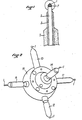
- Figure 1 which shows in section and at an enlargement of the order of 40 an elementary multidirectional light source according to the present invention, it includes a ball 1 frosted in non-expanded polystyrene with a diameter of 0.5 mm.
- the support for the transmission of the light flux necessary for the radiation of the ball 1 comprises an optical fiber 2 with a diameter of 0.2 mm fitted and glued at 7 to the center of the ball 1.
- the rigidity of the optical fiber 2 is obtained thanks to the adding a peripheral metal tube 3 of small thickness and an external plastic body 5 machined after molding.
- FIG. 2 shows in perspective another embodiment of a multidirectional light source according to the present invention, namely a composite multidirectional light source comprising five elementary light sources 10, 11, 12, 13 and 14, each being identical to the illustrated light source in Figure 1.
- a composite multidirectional light source comprising five elementary light sources 10, 11, 12, 13 and 14, each being identical to the illustrated light source in Figure 1.
- Four of the five previous sources, 10, 11, 12 and 13 are in the same plane and are located in this plane two by two along two axes of rectangular coordinates: for example, sources 10 and 12 are arranged on an axis XOX 'and the sources 11 and 13 are arranged on an axis YOY' perpendicular to the axis XOX '.
- the fifth source elementary 14 is arranged on an axis OZ forming a triangular trihedron with the axes XOX 'and YOY' previously defined.
- the light energy generator 4 of FIG. 3 which supplies the five elementary light sources 10 to 14 can be easily housed inside a movable cylindrical dome 15 which supports the five light sources.
- FIG. 4 illustrates an example of application according to which the position and the orientation of the end of a polyarticulated assembly such as a robot 22 are measured.
- the measurement is carried out using two theodolites 20, 21 which allow, after an appropriate calculation, to give the position x, y, z, in a chosen reference frame, of a light point such as the ball 1 of the multidirectional light source 14 carried by the movable dome 15 constituting the end of the robot 22 as shown in Figure 4, light source located in the measurement space.
Landscapes
- Physics & Mathematics (AREA)
- General Physics & Mathematics (AREA)
- Optics & Photonics (AREA)
- Investigating Or Analysing Materials By Optical Means (AREA)
- Length Measuring Devices By Optical Means (AREA)
- Optical Couplings Of Light Guides (AREA)
- Light Guides In General And Applications Therefor (AREA)
Abstract
Description
- La présente invention se rapporte aux sources d'énergie rayonnante ponctuelle et plus particulièrement à la création de cibles lumineuses ponctuelles utilisées en métrologie optique dans le domaine des mesures tridimensionnelles à l'aide de théodolites.
- Toute surface ou volume qui émet un rayonnement constitue une source d'énergie rayonnante. Cette source est considérée comme ponctuelle si ses dimensions sont très petites par rapport à la distance qui la sépare du récepteur ou de l'observateur.
- Actuellement les impératifs de réalisation ou de fabrication des systèmes existants obligent à observer le compromis suivant :
- - quand la source est considérée comme ponctuelle, elle ne rayonne que suivant un très faible angle solide ;
- - le fait d'augmenter cet angle solide impose à la source des dimensions telle qu'elle ne peut plus être considérée comme ponctuelle.
- La présente invention permet d'éviter ces inconvénients.
- La source lumineuse multidirectionnelle élémentaire suivant la présente invention est remarquable en ce qu'elle comprend une fibre optique contenue sur au moins une partie de sa longueur dans un tube métallique de faible épaisseur mais suffisamment rigide et une bille dépolie faite en une substance capable de transmettre dans de bonnes conditions les rayons lumineux d'une gamme de longueurs d'onde déterminée, emmanchée et collée sur l'extrémité libre de ladite fibre optique.
- Suivant un mode de réalisation préféré, larbille dépolie qui est en polystyrène non expansé à un diamètre de l'ordre de 0,5 mm et le diamètre de la fibre optique est de l'ordre de 0,2 mm.
- Suivant un deuxième aspect la présente invention concerne une source lumineuse multidirectionnelle composite composée de cinq sources lumineuses élémentaires présentant les caractéristiques rappelées ci- dessus, remarquable en ce que quatre de ces sources élémentaires sont situées dans un plan suivant deux axes de coordonnées rectangulaires et en ce que la cinquième source élémentaire est disposée suivant l'axe perpendiculaire aux deux axes de coordonnées précédents en leur point d'intersection.
- Suivant un troisième aspect de la présente invention, qu'il s'agisse d'une source lumineuse multidirectionnelle élémentaire ou composite, celle-ci est utilisée à la mesure de la position et de l'orientation de l'extrémité d'un ensemble polyarticulé tel qu'un robot, et la mesure s'effectue à l'aide de deux théodolites.
- D'autres caractéristiques ressortiront de la description qui suit et qui n'est donnée qu'à titre d'exemple. A cet effet on se reportera aux dessins joints dans lesquels : .
- - la figure 1 représente en coupe et à un agrandissement de l'ordre de 40 un mode de réalisation d'une source lumineuse multidirectionnelle élémentaire suivant la présente invention ;
- - la figure 2 représente en perspective une source lumineuse multidirectionnelle composite comprenant cinq sources lumineuses élémentaires suivant la présente invention ;
- - la figure 3 représente schématiquement un générateur d'énergie lumineuse susceptible d'être associé à l'une ou à l'autre des sources lumineuses multidirectionnelles mentionnées précédemment ; et,
- - la figure 4 illustre une méthode de mesure tridimensionnelle à l'aide de deux théodolites faisant usage de l'une ou de l'autre des sources lumineuses-multidirectionnelles mentionnées précédemment.
- Suivant le mode de réalisation de la figure 1 qui représente en coupe et à un agrandissement de l'ordre de 40 une source lumineuse multidirectionnelle élémentaire suivant la présente invention, celle-ci comprend une bille 1 dépolie en polystyrène non expansé de diamètre 0,5 mm. Le support à la transmission du flux lumineux nécessaire au rayonnement de la bille 1 comprend une fibre optique 2 de diamètre 0,2 mm emmanchée et collée en 7 au centre de la bille 1. La rigidité de la fibre optique 2 est obtenue grâce à l'adjonction d'un tube métallique périphérique 3 de faible épaisseur et d'un corps en plastique extérieur 5 usiné après moulage.
- Un générateur d'énergie lumineuse 4 susceptible d'être associé à la source lumineuse multidirectionnelle de la figure 1 est représenté schématiquement à la figure 3. Il possède selon les besoins une ou plusieurs sorties par lesquelles passent les fibres optiques 2 de raccordement. Du fait que le générateur d'énergie lumineuse 4 peut être situé à une distance appréciable de la bille dépolie 1, il peut être d'un type classique et offrir les avantages suivants :
- - puissance grâce à des dimensions importantes ;
- - réglage en intensité en fonction des besoins spécifiques ;
- - refroidissement ;
- - possibilité d'alimenter plusieurs sources à la fois ;
- - possibilité de créer différents types de rayonnements tels que monochromatique, modulé, etc.
- La figure 2 représente en perspective un autre mode de réalisation de source lumineuse multidirectionnelle suivant la présente invention, à savoir une source lumineuse multidirectionnelle composite comprenant cinq sources lumineuses élémentaires 10, 11, 12, 13 et 14, chacune étant identique à la source lumineuse illustrée à la figure 1. Quatre des cinq sources précédentes, 10, 11, 12 et 13 sont dans un même plan et sont situées dans ce plan deux à deux suivant deux axes de coordonnées rectangulaires : par exemple, les sources 10 et 12 sont disposées sur un axe XOX' et les sources 11 et 13 sont disposées sur un axe YOY' perpendiculaire à l'axe XOX'. Dans ces conditions la cinquième source élémentaire 14 est disposée sur un axe OZ formant un trièdre trirectangle avec les axes XOX' et YOY' précédemment définis. Le générateur d'énergie lumineuse 4 de la figure 3 qui alimente les cinq sources lumineuses élémentaires 10 à 14 peut être aisément logé à l'intérieur d'une coupole cylindrique mobile 15 qui supporte les cinq sources lumineuses.
- La figure 4 illustre un exemple d'application suivant lequel on mesure la position et l'orientation de l'extrémité d'un ensemble polyarticulé tel qu'un robot 22. A cet effet la mesure s'effectue à l'aide de deux théodolites 20, 21 qui permettent, après un calcul approprié, de donner la position x, y, z, dans un référentiel choisi, d'un point lumineux tel que la bille 1 de la source lumineuse multidirectionnelle 14 portée par la-coupole mobile 15 constituant l'extrémité du robot 22 suivant la représentation de la figure 4, source lumineuse située dans l'espace de mesure.
- Pour cette opération, il faut, en plus de la position, déterminer l'orientation. Pour celà on utilise une cible multisources 15 à cinq sources dont trois seulement sont nécessaires. Mais, étant donné que suivant les positions de l'extrémité mobile 15, les zones ne sont pas toutes visables à chaque instant par les théodolites, il est nécessaire d'augmenter le nombre de sources. Une cible multisources 15 à cinq sources donne entière satisfaction.
Claims (4)
Applications Claiming Priority (2)
| Application Number | Priority Date | Filing Date | Title |
|---|---|---|---|
| FR8100938A FR2498338A1 (fr) | 1981-01-20 | 1981-01-20 | Source lumineuse multidirectionnelle et son application aux mesures de position et d'orientation |
| FR8100938 | 1981-01-20 |
Publications (3)
| Publication Number | Publication Date |
|---|---|
| EP0057626A2 true EP0057626A2 (fr) | 1982-08-11 |
| EP0057626A3 EP0057626A3 (en) | 1982-08-25 |
| EP0057626B1 EP0057626B1 (fr) | 1985-05-29 |
Family
ID=9254307
Family Applications (1)
| Application Number | Title | Priority Date | Filing Date |
|---|---|---|---|
| EP82400097A Expired EP0057626B1 (fr) | 1981-01-20 | 1982-01-19 | Cible lumineuse prévue pour être utilisée en métrologie optique dans le domaine des mesures tridimensionnelles et méthode de mesure |
Country Status (5)
| Country | Link |
|---|---|
| US (1) | US4407012A (fr) |
| EP (1) | EP0057626B1 (fr) |
| JP (1) | JPS57137804A (fr) |
| DE (1) | DE3263807D1 (fr) |
| FR (1) | FR2498338A1 (fr) |
Cited By (3)
| Publication number | Priority date | Publication date | Assignee | Title |
|---|---|---|---|---|
| CN105866149A (zh) * | 2016-04-08 | 2016-08-17 | 中国工程物理研究院核物理与化学研究所 | 一种类椭球形构件的定位方法 |
| CN105953771A (zh) * | 2016-06-14 | 2016-09-21 | 西安中科光电精密工程有限公司 | 一种主动式经纬仪系统及测量方法 |
| CN108007332A (zh) * | 2017-11-07 | 2018-05-08 | 中国核工业二三建设有限公司 | 多管径管口尺寸测量辅助工具 |
Families Citing this family (4)
| Publication number | Priority date | Publication date | Assignee | Title |
|---|---|---|---|---|
| US5000535A (en) * | 1989-11-28 | 1991-03-19 | Churchill David L | Fiber optics light bar |
| US6453568B1 (en) * | 1998-11-21 | 2002-09-24 | Jeff Hymer | Laser protractor |
| JP7374195B2 (ja) * | 2018-08-24 | 2023-11-06 | トリナミクス ゲゼルシャフト ミット ベシュレンクテル ハフツング | 少なくとも1つの物体の位置を決定するための検出器 |
| CN109870151B (zh) * | 2019-04-15 | 2023-06-23 | 湖南科技大学 | 曲率可调型曲线投线仪及用法 |
Family Cites Families (7)
| Publication number | Priority date | Publication date | Assignee | Title |
|---|---|---|---|---|
| US3018362A (en) * | 1959-07-16 | 1962-01-23 | Taylor C Joyce | Decorative light fixture |
| US3439157A (en) * | 1966-02-11 | 1969-04-15 | Singer General Precision | Point light source |
| US3644725A (en) * | 1969-09-11 | 1972-02-22 | Robert L Lochridge Jr | Light display apparatus |
| US3813514A (en) * | 1972-10-16 | 1974-05-28 | J Canty | Light piping unit for supplying radiant energy to the interior of a pressure vessel |
| US4097917A (en) * | 1976-06-07 | 1978-06-27 | Mccaslin Robert E | Rotatable light display |
| US4060722A (en) * | 1976-09-08 | 1977-11-29 | Foley Robert A | Fibre optics display |
| JPS54116258A (en) * | 1978-03-01 | 1979-09-10 | Nippon Aviotronics Kk | Apparatus for measuring multiidimensional moving position |
-
1981
- 1981-01-20 FR FR8100938A patent/FR2498338A1/fr active Granted
-
1982
- 1982-01-19 DE DE8282400097T patent/DE3263807D1/de not_active Expired
- 1982-01-19 EP EP82400097A patent/EP0057626B1/fr not_active Expired
- 1982-01-19 JP JP57005477A patent/JPS57137804A/ja active Pending
- 1982-01-20 US US06/341,138 patent/US4407012A/en not_active Expired - Fee Related
Cited By (6)
| Publication number | Priority date | Publication date | Assignee | Title |
|---|---|---|---|---|
| CN105866149A (zh) * | 2016-04-08 | 2016-08-17 | 中国工程物理研究院核物理与化学研究所 | 一种类椭球形构件的定位方法 |
| CN105866149B (zh) * | 2016-04-08 | 2018-04-10 | 中国工程物理研究院核物理与化学研究所 | 一种类椭球形构件的定位方法 |
| CN105953771A (zh) * | 2016-06-14 | 2016-09-21 | 西安中科光电精密工程有限公司 | 一种主动式经纬仪系统及测量方法 |
| CN105953771B (zh) * | 2016-06-14 | 2018-02-13 | 西安中科光电精密工程有限公司 | 一种主动式经纬仪系统及测量方法 |
| CN108007332A (zh) * | 2017-11-07 | 2018-05-08 | 中国核工业二三建设有限公司 | 多管径管口尺寸测量辅助工具 |
| CN108007332B (zh) * | 2017-11-07 | 2021-01-05 | 中国核工业二三建设有限公司 | 多管径管口尺寸测量辅助工具 |
Also Published As
| Publication number | Publication date |
|---|---|
| EP0057626B1 (fr) | 1985-05-29 |
| US4407012A (en) | 1983-09-27 |
| FR2498338A1 (fr) | 1982-07-23 |
| DE3263807D1 (en) | 1985-07-04 |
| EP0057626A3 (en) | 1982-08-25 |
| FR2498338B1 (fr) | 1984-10-26 |
| JPS57137804A (en) | 1982-08-25 |
Similar Documents
| Publication | Publication Date | Title |
|---|---|---|
| EP0487385B1 (fr) | Dispositif de visualisation collimaté à miroir sphérique hors d'axe pour simulateur | |
| EP0310493B1 (fr) | Dispositif optoélectrique de détection et de localisation d'une source rayonnante | |
| EP0712009A1 (fr) | Ecartomètre intégré | |
| EP0767925B1 (fr) | Jumelle compacte de vision nocturne | |
| EP0072840B1 (fr) | Procede de multiplexage de voies de transmission au sein d'une fibre optique a saut d'indice et dispositif de mise en oeuvre | |
| EP0057626B1 (fr) | Cible lumineuse prévue pour être utilisée en métrologie optique dans le domaine des mesures tridimensionnelles et méthode de mesure | |
| EP0778958B1 (fr) | Systeme de reperage d'orientation d'un instrument d'observation | |
| EP0196980B1 (fr) | Système de collimatage pour télémétrie optique | |
| EP0321048B1 (fr) | Illuminateur de forte puissance pour caméra | |
| WO1993020416A1 (fr) | Dispositif optique du type deflectometre, notamment a detection de phase, a grand domaine de mesure | |
| GB2027931A (en) | Geodesic lens for waveguides and optical processor of unidimensional signals employing the same | |
| CH328493A (fr) | Dispositif pour augmenter la profondeur du champ d'un objectif | |
| EP4291935B1 (fr) | Système et procédé d'observation et procédé de fabrication d'un tel système | |
| FR3006759A1 (fr) | Systeme optique de mesure d'orientation et de position a source ponctuelle, masque central, capteur matriciel photosensible et coin de cube | |
| EP0005705A1 (fr) | Lunette optique et son application à la réalisation de jumelles | |
| FR2661518A1 (fr) | Procede d'harmonisation entre l'axe d'une lunette de visee et celui d'une camera thermique. | |
| FR2709557A1 (fr) | Dispositif optique de mesure à distance des variations d'orientation d'un objet. | |
| EP1998208A2 (fr) | Jumelle bioculaire de vision nocturne | |
| JPH10141946A (ja) | セオドライト対向ミラー及び指向角測定方法 | |
| FR2653905A1 (fr) | Dispositif optique de correction des defauts introduits par un hublot spherique utilise hors d'axe. | |
| McGraw et al. | Lens systems for sky surveys and space surveillance | |
| US20060203360A1 (en) | Imaging system and optical components thereof | |
| EP1376101A1 (fr) | Dispositif de mesure de caractéristiques photométriques d'un matériau | |
| Geary et al. | Dragonfly directional sensor | |
| FR2925176A1 (fr) | Miroir d'imagerie, procede de fabrication et application a un systeme d'imagerie laser. |
Legal Events
| Date | Code | Title | Description |
|---|---|---|---|
| PUAI | Public reference made under article 153(3) epc to a published international application that has entered the european phase |
Free format text: ORIGINAL CODE: 0009012 |
|
| PUAL | Search report despatched |
Free format text: ORIGINAL CODE: 0009013 |
|
| 17P | Request for examination filed |
Effective date: 19820122 |
|
| AK | Designated contracting states |
Designated state(s): DE GB IT SE |
|
| AK | Designated contracting states |
Designated state(s): DE GB IT SE |
|
| ITF | It: translation for a ep patent filed | ||
| GRAA | (expected) grant |
Free format text: ORIGINAL CODE: 0009210 |
|
| AK | Designated contracting states |
Designated state(s): DE GB IT SE |
|
| REF | Corresponds to: |
Ref document number: 3263807 Country of ref document: DE Date of ref document: 19850704 |
|
| PLBE | No opposition filed within time limit |
Free format text: ORIGINAL CODE: 0009261 |
|
| STAA | Information on the status of an ep patent application or granted ep patent |
Free format text: STATUS: NO OPPOSITION FILED WITHIN TIME LIMIT |
|
| 26N | No opposition filed | ||
| PGFP | Annual fee paid to national office [announced via postgrant information from national office to epo] |
Ref country code: SE Payment date: 19890131 Year of fee payment: 8 Ref country code: GB Payment date: 19890131 Year of fee payment: 8 |
|
| PGFP | Annual fee paid to national office [announced via postgrant information from national office to epo] |
Ref country code: DE Payment date: 19891227 Year of fee payment: 9 |
|
| PG25 | Lapsed in a contracting state [announced via postgrant information from national office to epo] |
Ref country code: GB Effective date: 19900119 |
|
| PG25 | Lapsed in a contracting state [announced via postgrant information from national office to epo] |
Ref country code: SE Effective date: 19900120 |
|
| GBPC | Gb: european patent ceased through non-payment of renewal fee | ||
| PG25 | Lapsed in a contracting state [announced via postgrant information from national office to epo] |
Ref country code: DE Effective date: 19911001 |
|
| EUG | Se: european patent has lapsed |
Ref document number: 82400097.0 Effective date: 19901106 |