EP0057641A2 - Ölgewinnung durch Verbrennung an Ort und Stelle - Google Patents
Ölgewinnung durch Verbrennung an Ort und Stelle Download PDFInfo
- Publication number
- EP0057641A2 EP0057641A2 EP82400150A EP82400150A EP0057641A2 EP 0057641 A2 EP0057641 A2 EP 0057641A2 EP 82400150 A EP82400150 A EP 82400150A EP 82400150 A EP82400150 A EP 82400150A EP 0057641 A2 EP0057641 A2 EP 0057641A2
- Authority
- EP
- European Patent Office
- Prior art keywords
- water
- oxidant gas
- oxygen
- inner conduit
- injected
- Prior art date
- Legal status (The legal status is an assumption and is not a legal conclusion. Google has not performed a legal analysis and makes no representation as to the accuracy of the status listed.)
- Granted
Links
Images

Classifications
-
- E—FIXED CONSTRUCTIONS
- E21—EARTH OR ROCK DRILLING; MINING
- E21B—EARTH OR ROCK DRILLING; OBTAINING OIL, GAS, WATER, SOLUBLE OR MELTABLE MATERIALS OR A SLURRY OF MINERALS FROM WELLS
- E21B43/00—Methods or apparatus for obtaining oil, gas, water, soluble or meltable materials or a slurry of minerals from wells
- E21B43/16—Enhanced recovery methods for obtaining hydrocarbons
- E21B43/24—Enhanced recovery methods for obtaining hydrocarbons using heat, e.g. steam injection
- E21B43/243—Combustion in situ
-
- E—FIXED CONSTRUCTIONS
- E21—EARTH OR ROCK DRILLING; MINING
- E21B—EARTH OR ROCK DRILLING; OBTAINING OIL, GAS, WATER, SOLUBLE OR MELTABLE MATERIALS OR A SLURRY OF MINERALS FROM WELLS
- E21B36/00—Heating, cooling or insulating arrangements for boreholes or wells, e.g. for use in permafrost zones
- E21B36/001—Cooling arrangements
-
- E—FIXED CONSTRUCTIONS
- E21—EARTH OR ROCK DRILLING; MINING
- E21B—EARTH OR ROCK DRILLING; OBTAINING OIL, GAS, WATER, SOLUBLE OR MELTABLE MATERIALS OR A SLURRY OF MINERALS FROM WELLS
- E21B41/00—Equipment or details not covered by groups E21B15/00 - E21B40/00
- E21B41/0078—Nozzles used in boreholes
Definitions
- the oxygen pipe as described in U.S. Patent 3,208,519 may reach a temperature where destruction of the pipe may occur.
- the pipe could be deformed or attacked by the heat. It can also be subjected to a sand blasting caused by the turbulence of the unconsolidated sand surrounding the injection well, this agitation caused by the high flow of oxidizing gas.
- the unprotected oxygen pipe, as described in U.S. Patent 3,208,519, is thus exposed to numerous hazards.
- an apparatus has the following characteristics.
- Terminal means closes the lower end of the outer conduit and provides a restricted passage in communication with the inner conduit for injecting oxygen or water or both into the formation.
- Means is provided for supplying oxidant gas under pressure to the upper end of the inner conduit.
- Means is also provided for supplying water to circulate within the cooling jacket.
- the inner conduit is connected to the injection passage and the cooling jacket isolated from it so that only oxygen is injected through the injection passage.
- the conduit is connected to the injection passage and there is a communication between the jacket and the injection passage so that both water and oxidizing gas may be injected.
- a water conduit leads from the surface to near the bottom of the water jacket so that water is introduced at the bottom to circulate upwards.
- a method according to the invention employs an apparatus, as described, in recovering oil in which there are a number of potential variations including the following.
- the oxidant gas may be supplied at a pressure such that the velocity at the injection passage is greater than the maximum possible flame velocity.
- the oxidant gas velocity at the injection passage may be greater than 90 feet per second.
- water may be injected at a reduced flow rate. Water may be injected at a rate less than 25% of the average normal requirement based on a unit of injected.oxygen gas.
- the oxidant gas may be injected at a reduced flow rate. The oxidant gas may be injected at a rate less than 25% of the average normal requirement based on a unit of water.
- the oxidant gas will be molecular oxygen containing more than 30% by.volume of oxygen gas. Commercial oxygen may be employed.
- the invention makes it possible to introduce the oxygen and /or water safely through a single opening at the outlet of the injection pipe into the oil bearing formation.
- the invention overcomes the hazards by placing the oxygen pipe concentrically inside a larger pipe, and using the resulting annular space for conveying the injected water.
- This water also serves to cool the large outer pipe and hence minimizes the effects of any severe thermal conditions.
- this outer pipe serves to protect the oxygen inner pipe from any sand blasting.
- Another feature of the present invention is the design of the oxygen outlet from the pipe into the reservoir.
- the velocity of oxygen is maintained sufficiently great to prevent flame propagation back into the pipe. This is achieved by constricting the oxygen outlet to maintain a minimum velocity of greater than 90 .ft/sec.
- Still another feature of the invention is the simultaneous injection of water and molecular oxygen into the formation from the same opening, whereby the oxygen atomizes the water to obtain a mist, thereby uniformly mixing the oxygen and water as the mixture flows from the production well into the formation.
- the molar ratio of water/oxygen is generally about 9. As long as a flame front can be sustained, the high ratio is the safest method to introduce molecular oxygen into the formation.
- a feature of this invention eliminates another hazard.
- the pipe conveying the air down the well terminates within the casing creating a confined annular space where explosive mixtures can be contained and where the casing is subjected to the possible hostile environment.
- the present invention requires that the concentric water cooled injection configuration extends beyond the end of the casing by a substantial distance.
- the well casing can be terminated at the top of the oil bearing zone and the injection pipe configuration can extend to the base of the oil zone.
- the injection cycle could be, for example, two-thirds of the time on oxygen and one-third of the time on water.
- the injection technique is most securely carried out by using the same and only outlet for both the injected fluids.
- the opening is designed to maintain an oxygen velocity of at least 90 ft/sec.
- water is injected into the reservoir through the same opening. At all times, either oxygen or water is flowing through said opening into the reservoir. This practice ensures that the oxygen pipe cannot become contaminated with hydrocarbon, neither liquid or gaseous.
- the oxygen is flowing continuously and always diluted with some water in the form of a spray or mist. Again, a continuous water flow through the annulus is useful in keeping the outside pipe from overheating.
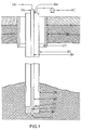
- the drawings merely show the input well which is used to supply oxygen to cause combustion of a portion of the oil in the oil recovery site to cause oil to flow toward an output well (not shown) spaced from the input well.
- the combustion front is propagated from the input well towards the output well.
- molecular oxygen and water are simultaneously, continuously and uniformly injected from the well into the formation, where molecular oxygen flowrate is 200,000 scf/day at 800 psig and the water flowrate is 200 barrel/day.
- the central tube (b) for the oxygen flow (a) is made of mild steel or stainless steel, schedule 80, 1/2" nominal pipe size.
- the last 10 feet of this pipe (g) at the bottom of the well is schedule 160, 1/2" nominal pipe, either, stainless steel, nickel, monel or other oxidation and heat resistant alloy.
- An annular steel pipe (d), schedule 80, 2" nominal size is concentrically placed over the central oxygen pipe for the full length of the well, where the lowest portion, which is within the oil bearing zone, say for.example, about 40 ft, is schedule 160, stainless, nickel, monel or other resistant alloys.
- a bottom plate (k) constructed with an opening (1) with a throat (i) which gives the molecular oxygen a velocity greater than 90 ft/sec.
- a throat (i) which gives the molecular oxygen a velocity greater than 90 ft/sec.
- the gas pressure is 800 psig and the throat is 0.2" diameter
- the velocity is 200 ft/sec.
- the throat is 0.28" diameter
- the oxygen velocity is about 100 ft/sec.
- Opening (1) the only opening for the injected fluids to enter the formation.
- Water is injected into the oxygen stream through a connecting passage (i) which is designed with an orifice of 1/4" diameter to obtain a pressure drop of about 5 to 10 psi ensuring that oxygen cannot flow back into the annular space.
- this component (k) is constructed of material resistant to the exposed environment at the injection well.
- This example corresponds to Case II and Figure II, where oxygen and water are alternately injected into the formation.
- molecular oxygen is to be injected at a rate of 30 0,000 cf/day for two days, followed by injection of 600 barrels of water/day for one day, to complete a three day cycle.
- the velocity of the molecular oxygen at the throat (k) be greater than 90 ft/sec.
- the throat (j) is 0.24 in diameter.
- the throat is 0.34 in diameter.
- the opening (1) is also used for the injected water into the formation, the water being introduced by the same pipe (b) as for the oxygen.
- the 0.24" diameter results in a pressure drop of about 250 psi across the opening (1).
- a pressure drop of about 65 psig occurs across the throat.
- the cooling water in the annular space (m) at the bottom of the well may be circulated by introducing the cooling water to the bottom via pipe (o) and overflowing the return cooling water at the top of the well at outlet (p).
- molecular oxygen or any reactive oxidant including air, and oxygen enriched air can also employ the invention to minimize the hazards and to protect the oxygen pipe against the possible hostile environment surrounding the injection well.
Landscapes
- Geology (AREA)
- Life Sciences & Earth Sciences (AREA)
- Engineering & Computer Science (AREA)
- Mining & Mineral Resources (AREA)
- Environmental & Geological Engineering (AREA)
- Fluid Mechanics (AREA)
- Physics & Mathematics (AREA)
- General Life Sciences & Earth Sciences (AREA)
- Geochemistry & Mineralogy (AREA)
- Lubricants (AREA)
- Removal Of Floating Material (AREA)
- Air Supply (AREA)
- Spray-Type Burners (AREA)
- Nozzles For Spraying Of Liquid Fuel (AREA)
Priority Applications (1)
| Application Number | Priority Date | Filing Date | Title |
|---|---|---|---|
| AT82400150T ATE13214T1 (de) | 1981-01-28 | 1982-01-28 | Oelgewinnung durch verbrennung an ort und stelle. |
Applications Claiming Priority (2)
| Application Number | Priority Date | Filing Date | Title |
|---|---|---|---|
| CA369497 | 1981-01-28 | ||
| CA000369497A CA1170979A (en) | 1981-01-28 | 1981-01-28 | In situ combustion for oil recovery |
Publications (3)
| Publication Number | Publication Date |
|---|---|
| EP0057641A2 true EP0057641A2 (de) | 1982-08-11 |
| EP0057641A3 EP0057641A3 (en) | 1982-08-25 |
| EP0057641B1 EP0057641B1 (de) | 1985-05-08 |
Family
ID=4119024
Family Applications (1)
| Application Number | Title | Priority Date | Filing Date |
|---|---|---|---|
| EP82400150A Expired EP0057641B1 (de) | 1981-01-28 | 1982-01-28 | Ölgewinnung durch Verbrennung an Ort und Stelle |
Country Status (7)
| Country | Link |
|---|---|
| US (1) | US4509595A (de) |
| EP (1) | EP0057641B1 (de) |
| AT (1) | ATE13214T1 (de) |
| BR (1) | BR8200488A (de) |
| CA (1) | CA1170979A (de) |
| DE (1) | DE3263614D1 (de) |
| MX (1) | MX159540A (de) |
Cited By (3)
| Publication number | Priority date | Publication date | Assignee | Title |
|---|---|---|---|---|
| FR2548207A1 (fr) * | 1983-06-30 | 1985-01-04 | Air Liquide | Procede d'oxydation de couches sedimentaires souterraines contenant des matieres hydrocarbonees |
| CN101818637A (zh) * | 2010-04-26 | 2010-09-01 | 胡士清 | 一种通过控制火烧注气速度提高厚层块状稠油油藏采收率的方法 |
| CN104122295A (zh) * | 2014-07-25 | 2014-10-29 | 中国石油大学(北京) | 燃烧池实验装置、能够测定活化能的实验装置和测量方法 |
Families Citing this family (5)
| Publication number | Priority date | Publication date | Assignee | Title |
|---|---|---|---|---|
| CA1289868C (en) * | 1987-01-13 | 1991-10-01 | Robert Lee | Oil recovery |
| US4778010A (en) * | 1987-03-18 | 1988-10-18 | Union Carbide Corporation | Process for injection of oxidant and liquid into a well |
| US4834178A (en) * | 1987-03-18 | 1989-05-30 | Union Carbide Corporation | Process for injection of oxidant and liquid into a well |
| CN102486085B (zh) * | 2010-12-01 | 2015-06-17 | 新奥气化采煤有限公司 | 一种用于含碳有机质地下气化的气化剂输配系统及工艺 |
| CN103742121B (zh) * | 2014-01-14 | 2017-01-25 | 新奥气化采煤有限公司 | 地下气化注气装置和方法 |
Family Cites Families (24)
| Publication number | Priority date | Publication date | Assignee | Title |
|---|---|---|---|---|
| US3126960A (en) * | 1964-03-31 | Method for the completion of a well bore | ||
| US2148717A (en) * | 1937-01-21 | 1939-02-28 | Alvin M Whitney | Process of extracting oil from oil sands |
| US2722277A (en) * | 1950-01-27 | 1955-11-01 | Socony Mobil Oil Co Inc | Recovery by combustion of petroleum oil from partially depleted subterranean reservoirs |
| US2906337A (en) * | 1957-08-16 | 1959-09-29 | Pure Oil Co | Method of recovering bitumen |
| US3007520A (en) * | 1957-10-28 | 1961-11-07 | Phillips Petroleum Co | In situ combustion technique |
| US2994375A (en) * | 1957-12-23 | 1961-08-01 | Phillips Petroleum Co | Recovery of hydrocarbons by in situ combustion |
| US3019838A (en) * | 1959-12-30 | 1962-02-06 | Texaco Inc | Well bore completion method |
| US3208519A (en) * | 1961-07-17 | 1965-09-28 | Exxon Production Research Co | Combined in situ combustion-water injection oil recovery process |
| US3160208A (en) * | 1961-10-06 | 1964-12-08 | Shell Oil Co | Production well assembly for in situ combustion |
| US3180411A (en) * | 1962-05-18 | 1965-04-27 | Phillips Petroleum Co | Protection of well casing for in situ combustion |
| US3196945A (en) * | 1962-10-08 | 1965-07-27 | Pan American Petroleum Company | Method of forward in situ combustion with water injection |
| US3343598A (en) * | 1965-02-03 | 1967-09-26 | Phillips Petroleum Co | Protection of production well equipment in in situ combustion operation |
| FR1473669A (fr) * | 1966-03-31 | 1967-03-17 | Deutsche Erdoel Ag | Procédé pour l'épuisement intégral des gisements de pétrole |
| US3438437A (en) * | 1966-07-11 | 1969-04-15 | Carl Edward Christofferson | Convector type heat exchanger |
| DE1247238B (de) * | 1966-08-12 | 1967-08-17 | Erdoel Ag Hamburg Deutsche | Verfahren zum Foerdern von Bitumina aus Lagerstaetten |
| US3456722A (en) * | 1966-12-29 | 1969-07-22 | Phillips Petroleum Co | Thermal-operated valve |
| US3457995A (en) * | 1967-01-03 | 1969-07-29 | Phillips Petroleum Co | Igniting an underground formation |
| US3441083A (en) * | 1967-11-09 | 1969-04-29 | Tenneco Oil Co | Method of recovering hydrocarbon fluids from a subterranean formation |
| US3456734A (en) * | 1968-01-05 | 1969-07-22 | Phillips Petroleum Co | Protection of well casing from thermal overstressing |
| US4042026A (en) * | 1975-02-08 | 1977-08-16 | Deutsche Texaco Aktiengesellschaft | Method for initiating an in-situ recovery process by the introduction of oxygen |
| US4058164A (en) * | 1976-04-12 | 1977-11-15 | Stoddard Xerxes T | Heating mine water for recovery of immobile hydrocarbons |
| US4099567A (en) * | 1977-05-27 | 1978-07-11 | In Situ Technology, Inc. | Generating medium BTU gas from coal in situ |
| US4147213A (en) * | 1978-02-22 | 1979-04-03 | Standard Oil Company (Indiana) | Combustion air injection well |
| US4274487A (en) * | 1979-01-11 | 1981-06-23 | Standard Oil Company (Indiana) | Indirect thermal stimulation of production wells |
-
1981
- 1981-01-28 CA CA000369497A patent/CA1170979A/en not_active Expired
-
1982
- 1982-01-22 US US06/341,677 patent/US4509595A/en not_active Expired - Lifetime
- 1982-01-27 MX MX191167A patent/MX159540A/es unknown
- 1982-01-28 AT AT82400150T patent/ATE13214T1/de not_active IP Right Cessation
- 1982-01-28 EP EP82400150A patent/EP0057641B1/de not_active Expired
- 1982-01-28 BR BR8200488A patent/BR8200488A/pt unknown
- 1982-01-28 DE DE8282400150T patent/DE3263614D1/de not_active Expired
Cited By (6)
| Publication number | Priority date | Publication date | Assignee | Title |
|---|---|---|---|---|
| FR2548207A1 (fr) * | 1983-06-30 | 1985-01-04 | Air Liquide | Procede d'oxydation de couches sedimentaires souterraines contenant des matieres hydrocarbonees |
| EP0131499A1 (de) * | 1983-06-30 | 1985-01-16 | L'air Liquide, Societe Anonyme Pour L'etude Et L'exploitation Des Procedes Georges Claude | Verfahren zur Oxydation von kohlenwasserstoffhaltigen untertägigen sedimentären Lagerstätten |
| CN101818637A (zh) * | 2010-04-26 | 2010-09-01 | 胡士清 | 一种通过控制火烧注气速度提高厚层块状稠油油藏采收率的方法 |
| CN101818637B (zh) * | 2010-04-26 | 2012-11-21 | 中国石油天然气股份有限公司 | 一种通过控制火烧注气速度提高厚层块状稠油油藏采收率的方法 |
| CN104122295A (zh) * | 2014-07-25 | 2014-10-29 | 中国石油大学(北京) | 燃烧池实验装置、能够测定活化能的实验装置和测量方法 |
| CN104122295B (zh) * | 2014-07-25 | 2016-10-12 | 中国石油大学(北京) | 燃烧池实验装置、能够测定活化能的实验装置和测量方法 |
Also Published As
| Publication number | Publication date |
|---|---|
| CA1170979A (en) | 1984-07-17 |
| ATE13214T1 (de) | 1985-05-15 |
| EP0057641A3 (en) | 1982-08-25 |
| EP0057641B1 (de) | 1985-05-08 |
| MX159540A (es) | 1989-06-29 |
| US4509595A (en) | 1985-04-09 |
| BR8200488A (pt) | 1982-11-30 |
| DE3263614D1 (en) | 1985-06-13 |
Similar Documents
| Publication | Publication Date | Title |
|---|---|---|
| US4398604A (en) | Method and apparatus for producing a high pressure thermal vapor stream | |
| CN104204669B (zh) | 具有多个喷射器的沉浸式燃烧器 | |
| CA1254505A (en) | Exploitation method for reservoirs containing hydrogen sulphide | |
| EP0051127B1 (de) | Tiefloch-Dampferzeuger mit direkter Feuerung | |
| US6096261A (en) | Coherent jet injector lance | |
| CA1064385A (en) | Combustion chamber and thermal vapor stream producing apparatus and method | |
| EP0057641A2 (de) | Ölgewinnung durch Verbrennung an Ort und Stelle | |
| AU644964B2 (en) | Electrical submersible pump for lifting heavy oils | |
| US8684072B2 (en) | Downhole gas generator | |
| CN106062307B (zh) | 产油系统和方法 | |
| CA2038649A1 (en) | Catalytic downhole reactor and steam generator | |
| US20110036095A1 (en) | Thermal vapor stream apparatus and method | |
| US3545903A (en) | Burner for preheating a refractory lined vessel | |
| RU2030569C1 (ru) | Способ разрыва пласта и устройство для его осуществления | |
| CN102527308A (zh) | 用于高温工业过程的具有改进的安全特征的装置 | |
| US2294168A (en) | Gas burner for heating the interior of circular vessels | |
| JPS6150630A (ja) | ガスを接触させる方法と装置 | |
| US3817332A (en) | Method and apparatus for catalytically heating wellbores | |
| US5832999A (en) | Method and assembly for igniting a burner assembly | |
| US5165483A (en) | Direct contact vapor generator fire suppression apparatus | |
| US3343598A (en) | Protection of production well equipment in in situ combustion operation | |
| US3127156A (en) | Figure | |
| US3604698A (en) | Apparatus and process for the gaseous deoxidation of anode copper | |
| NO821883L (no) | Varmebehandlingsapparat | |
| US3712375A (en) | Method for catalytically heating wellbores |
Legal Events
| Date | Code | Title | Description |
|---|---|---|---|
| PUAI | Public reference made under article 153(3) epc to a published international application that has entered the european phase |
Free format text: ORIGINAL CODE: 0009012 |
|
| PUAL | Search report despatched |
Free format text: ORIGINAL CODE: 0009013 |
|
| 17P | Request for examination filed |
Effective date: 19820219 |
|
| AK | Designated contracting states |
Designated state(s): AT BE CH DE FR GB IT LU NL SE |
|
| AK | Designated contracting states |
Designated state(s): AT BE CH DE FR GB IT LU NL SE |
|
| ITF | It: translation for a ep patent filed | ||
| GRAA | (expected) grant |
Free format text: ORIGINAL CODE: 0009210 |
|
| AK | Designated contracting states |
Designated state(s): AT BE CH DE FR GB IT LI LU NL SE |
|
| REF | Corresponds to: |
Ref document number: 13214 Country of ref document: AT Date of ref document: 19850515 Kind code of ref document: T |
|
| REF | Corresponds to: |
Ref document number: 3263614 Country of ref document: DE Date of ref document: 19850613 |
|
| ET | Fr: translation filed | ||
| PLBE | No opposition filed within time limit |
Free format text: ORIGINAL CODE: 0009261 |
|
| STAA | Information on the status of an ep patent application or granted ep patent |
Free format text: STATUS: NO OPPOSITION FILED WITHIN TIME LIMIT |
|
| 26N | No opposition filed | ||
| PGFP | Annual fee paid to national office [announced via postgrant information from national office to epo] |
Ref country code: NL Payment date: 19890131 Year of fee payment: 10 |
|
| PGFP | Annual fee paid to national office [announced via postgrant information from national office to epo] |
Ref country code: CH Payment date: 19901217 Year of fee payment: 10 |
|
| PGFP | Annual fee paid to national office [announced via postgrant information from national office to epo] |
Ref country code: SE Payment date: 19901220 Year of fee payment: 10 |
|
| PGFP | Annual fee paid to national office [announced via postgrant information from national office to epo] |
Ref country code: BE Payment date: 19901221 Year of fee payment: 10 |
|
| PGFP | Annual fee paid to national office [announced via postgrant information from national office to epo] |
Ref country code: LU Payment date: 19910108 Year of fee payment: 10 |
|
| EPTA | Lu: last paid annual fee | ||
| PG25 | Lapsed in a contracting state [announced via postgrant information from national office to epo] |
Ref country code: LU Free format text: LAPSE BECAUSE OF NON-PAYMENT OF DUE FEES Effective date: 19920128 |
|
| PG25 | Lapsed in a contracting state [announced via postgrant information from national office to epo] |
Ref country code: SE Effective date: 19920129 |
|
| PG25 | Lapsed in a contracting state [announced via postgrant information from national office to epo] |
Ref country code: LI Effective date: 19920131 Ref country code: CH Effective date: 19920131 Ref country code: BE Effective date: 19920131 |
|
| BERE | Be: lapsed |
Owner name: CANADIAN LIQUID AIR LTD AIR LIQUIDE CANADA LTEE Effective date: 19920131 |
|
| PG25 | Lapsed in a contracting state [announced via postgrant information from national office to epo] |
Ref country code: NL Effective date: 19920801 |
|
| NLV4 | Nl: lapsed or anulled due to non-payment of the annual fee | ||
| REG | Reference to a national code |
Ref country code: CH Ref legal event code: PL |
|
| PGFP | Annual fee paid to national office [announced via postgrant information from national office to epo] |
Ref country code: AT Payment date: 19921210 Year of fee payment: 12 |
|
| PGFP | Annual fee paid to national office [announced via postgrant information from national office to epo] |
Ref country code: GB Payment date: 19921216 Year of fee payment: 12 |
|
| ITTA | It: last paid annual fee | ||
| PG25 | Lapsed in a contracting state [announced via postgrant information from national office to epo] |
Ref country code: AT Effective date: 19940128 Ref country code: GB Effective date: 19940128 |
|
| GBPC | Gb: european patent ceased through non-payment of renewal fee |
Effective date: 19940128 |
|
| EUG | Se: european patent has lapsed |
Ref document number: 82400150.7 Effective date: 19920806 |
|
| PGFP | Annual fee paid to national office [announced via postgrant information from national office to epo] |
Ref country code: FR Payment date: 19991213 Year of fee payment: 19 |
|
| PGFP | Annual fee paid to national office [announced via postgrant information from national office to epo] |
Ref country code: DE Payment date: 19991227 Year of fee payment: 19 |
|
| PG25 | Lapsed in a contracting state [announced via postgrant information from national office to epo] |
Ref country code: FR Free format text: LAPSE BECAUSE OF NON-PAYMENT OF DUE FEES Effective date: 20010928 |
|
| PG25 | Lapsed in a contracting state [announced via postgrant information from national office to epo] |
Ref country code: DE Free format text: LAPSE BECAUSE OF NON-PAYMENT OF DUE FEES Effective date: 20011101 |
|
| REG | Reference to a national code |
Ref country code: FR Ref legal event code: ST |