EP0057646A2 - Ensemble de microscope éléctronique à balayage à fonctionnement in situ - Google Patents
Ensemble de microscope éléctronique à balayage à fonctionnement in situ Download PDFInfo
- Publication number
- EP0057646A2 EP0057646A2 EP82400176A EP82400176A EP0057646A2 EP 0057646 A2 EP0057646 A2 EP 0057646A2 EP 82400176 A EP82400176 A EP 82400176A EP 82400176 A EP82400176 A EP 82400176A EP 0057646 A2 EP0057646 A2 EP 0057646A2
- Authority
- EP
- European Patent Office
- Prior art keywords
- column
- assembly according
- interior chamber
- microscope
- peripheral
- Prior art date
- Legal status (The legal status is an assumption and is not a legal conclusion. Google has not performed a legal analysis and makes no representation as to the accuracy of the status listed.)
- Granted
Links
Images
Classifications
-
- H—ELECTRICITY
- H01—ELECTRIC ELEMENTS
- H01J—ELECTRIC DISCHARGE TUBES OR DISCHARGE LAMPS
- H01J37/00—Discharge tubes with provision for introducing objects or material to be exposed to the discharge, e.g. for the purpose of examination or processing thereof
- H01J37/02—Details
- H01J37/18—Vacuum locks ; Means for obtaining or maintaining the desired pressure within the vessel
-
- H—ELECTRICITY
- H01—ELECTRIC ELEMENTS
- H01J—ELECTRIC DISCHARGE TUBES OR DISCHARGE LAMPS
- H01J2237/00—Discharge tubes exposing object to beam, e.g. for analysis treatment, etching, imaging
- H01J2237/26—Electron or ion microscopes
- H01J2237/2602—Details
- H01J2237/2605—Details operating at elevated pressures, e.g. atmosphere
Definitions
- the present invention relates to scanning electron microscopes and, more particularly, to a scanning electron microscope with in situ operation.
- scanning electron microscopes has known, in recent years, a lightning development because of their flexibility of use, in association in particular with cathode-ray display screens, and of their extremely appreciable performances of observation, in particular in which concerns the depth of field. These characteristics make scanning electron microscopes particularly advantageous, industrially, for the control of surfaces of structural or operational parts, in particular for the control of manufacturing processes or the study of surface deformations during stress tests. Until now, the study of such surfaces has been done by conventional optical methods using magnifying glasses or optical microscopes, with the associated drawbacks. low magnification, and especially limited depth of field. It therefore appears particularly plausible to use scanning electron microscopes for such checks because of their advantages mentioned above.
- an observation technique has been proposed using an electron microscope, using a small vacuum intermediate enclosure connected to a powerful pumping device and opening out to the right of the area to be observed by a very small aperture diaphragm. (of the order of 30 microns) and of small thickness, in order to limit as much as possible the air leakage rate to be permanently compensated by the pumping device.
- the technique thus proposed suffers from numerous limitations, notably due to the very limited field of observation, due to the microscopic dimension of the diaphragm, to the non-homogeneity of the vacuum at the level of the optical axis as well as to the diffusion of the electrons. backscattered by the object resulting in poor quality images.
- the object of the present invention is precisely to obviate these drawbacks by proposing a set of scanning electron microscope operating in situ, of light and transportable construction, which can be placed directly on the object to be examined without any particular preparation thereof. , by allowing direct observation of the object in question in its natural environment, by making it possible to obtain strong magnifications with a significant depth of field (for example of the order of a thousand times greater than with an optical microscope) for a fast, flexible and non-destructive study in situ, for example of airplane wings, or for the control of parts machined or worked with precision, such as glass lenses or mirrors of optical systems.
- a significant depth of field for example of the order of a thousand times greater than with an optical microscope
- the set of electron microscope to scanning in situ operation comprising a column of unitary electron microscope, means of connection to an installation for command and control of the microscope and to a pumping installation, comprises a support means for the column, connected to the lower part of the latter, and defining an interior chamber having a lower open part intended to be placed in sealed abutment on a peripheral surface integral with the zone to be observed, means being provided for placing the interior chamber in communication with a transportable pumping installation.
- the support means comprises a pressure-resistant peripheral wall or skirt defining the interior chamber and flexible sealing means delimiting the lower open part of the chamber and intended to be applied to the support surface to be observed.
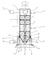
- the scanning electron microscope assembly with in situ operation essentially comprises an electron microscope column 1, of small dimensions and of reduced weight, connected to an electronic command and control installation. adequate 2, a column support means 3 defining an interior chamber 4, connected as well as the column 1, to a powerful and portable pumping device 40.
- the column 1 comprises a hermetic tubular frame 5 containing, successively , an electron gun 6, a stage 7 of two condensers 7 1 and 7 a stage of objective lens 8 with a stigmator 9 and coils ie scanning 10 in a tubular conduit 11 extending to the vicinity of the bottom of a frustoconical cover 12 converging downwards, closing the column 1 and provided with a central opening 13 for passage of the electron beam around which the annular electron detector 14 concentric to the optical axis 15 of column 1.
- the support means 3 of the column 1 comprises a wall or peripheral skirt with resistance in shape 16, pressure resistant, for example a stainless steel ferrule, defining the interior chamber 4, in which the cover projects frustoconical lower 12 and on the edge of the open end of which is fixed a peripheral elastic seal 17, for example of solid or selectively inflatable elastomeric material.
- the support means further comprises a height adjustment system or jacks 18, 18 ′, making it possible to precisely adjust the distance between the detector 14 and the area to be observed A from the surface 19 ′ of the surface over a determined range. body 19 to be studied.
- a connector 20, mounted in the wall 16, allows the connection of the detector 14 to the command and control installation 2.
- the wall 16 also comprises, laterally, a sleeve 21 for connection to the pumping device 4.
- the column 1 is connected to the upper end of the support wall 16 by a ball joint system 22, for example with cooperating teflon toroidal surfaces, the sealing at the level of the ball joint 22 being ensured by a flexible membrane 23 of a metal alloy known under the name "Tombac" sealingly connecting the upper part of the wall 16 to a adjacent crown of the frustoconical cover 12.
- a ball joint system 22 for example with cooperating teflon toroidal surfaces, the sealing at the level of the ball joint 22 being ensured by a flexible membrane 23 of a metal alloy known under the name "Tombac" sealingly connecting the upper part of the wall 16 to a adjacent crown of the frustoconical cover 12.
- the microscope column 1 with its support 16 is brought into line with the area A to be studied, the assembly resting on the part to be studied 19 by the joint flexible 17, the application of the vacuum in the interior chamber 4 of the support means by the pumping device 40 ensuring in the latter, the degree of vacuum (of the order of 10 -4 mm of mercury) necessary for the operation of the microscope while also placing the seal 17 perfectly on the surface 19 ′, thus ensuring the required seal for the time necessary for observation.
- This device thus allows the study, on site, without prior preparation, of airplane wings or other surfaces with a resolving power of the order of 10 to 20 nanometers.
- the microscope column 1 is for example of the MIEL bis type developed by the electronic optics laboratory of the CNRS in Seattle, operating under a low voltage of the order of 10 to 15 kilovolts.
- the wall 16 of the support means can be extended radially inwards by a crown, itself terminated by the watertight seal 17, to limit the opening of the interior chamber 4.
Landscapes
- Chemical & Material Sciences (AREA)
- Analytical Chemistry (AREA)
- Analysing Materials By The Use Of Radiation (AREA)
Abstract
Description
- La présente invention concerne les microscopes électroniques à balayage et, plus particulièrement, un microscope électronique à balayage à fonctionnement in situ.
- L'utilisation des microscopes électroniques à balayage a connu, ces dernières années, un développement foudroyant en raison de leur souplesse d'utilisation, en association notamment avec des écrans cathodiques de visualisation, et de leurs performances extrêmement appréciables d'observation, notamment en ce qui concerne la profondeur de champ. Ces caractéristiques rendent les microscopes électroniques à balayage particulièrement avantageux, au plan industriel, pour le contrôle de surfaces de pièces structurelles ou opérationnelles, notamment pour le contrôle de procédés de fabrication ou l'étude de déformations de surfaces lors d'essais de contraintes. Jusqu'à présent,l`étude de telles surfaces était faite par des procédés optiques classiques utilisant des loupes ou des microscopes optiques, avec les inconvénients afférents. de faible grandissement, et surtout de profondeur de champ limitée. Il apparaît donc particulièrement tentant de mettre en oeuvre,pour de tels contrôles, des microscopes électroniques à balayage en raison de leurs avantages évoqués ci-dessus.Or, on le sait,en microscopie électronique, il est nécessaire d'introduire l'objet à observer sur un support spécial pour le placer dans une enceinte sous vide formant chambre d'observation pour le microscope.De ce fait, l'utilisation de microscopes électroniques imposait jusqu'à présent le recours à des techniques de préparation destructive des pièces,nécessitant le prélèvement d'un échantillon susceptible d'être placé dans la chambre d'observation,au prix, le plus souvent, d'une détérioration ou d'une déformation rédhibitoire de la zone à étudier.
- Pour obvier cet inconvénient, il a été proposé une technique d'observation au microscope électronique, utilisant une enceinte sous vide intermédiaire de faibles dimensions reliée à un dispositif de pompage puissant et débouchant au droit de la zone à observer par un diaphragme de très petite ouverture (de l'ordre de 30 microns) et de faible épaisseur, afin de limiter autant que faire se peut le débit de fuite d'air à compenser en permanence par le dispositif de pompage. La technique ainsi proposée souffre de nombreuses limitations, tenant notamment au champ très limité d'observation, du fait de la dimension microscopique du diaphragme, à la non-homogénéité du vide au niveau de l'axe optique ainsi qu'à la diffusion des électrons rétrodiffusés par l'objet entraînant des images de qualité médiocre.
- La présente invention a précisément pour objet d'obvier à ces inconvénients en proposant un ensemble de microscope électronique à balayage fonctionnant in situ, de construction légère et transportable, qui puisse être posé directement sur l'objet à examiner sans préparation particulière de celui- ci, en autorisant une observation directe de l'objet en question dans son environnement naturel, en permettant d'obtenir de forts grandissements avec une profondeur de champ importante (par exemple de l'ordre de mille fois plus grande qu'avec un microscope optique) pour une étude rapide, souple et non destructive in situ par exemple d'ailes d'avion,ou pour le contrôle de pièces usinées ou travaillées avec précision, telles que des lentilles de verre ou des miroirs de systèmes optiques.
- Pour ce faire, selon une caractéristique de la présente invention, l'ensemble de microscope électronique à balayage à fonctionnement in situ, comprenant une colonne de microscope électronique unitaire, des moyens de connexion à une installation de commande et de contrôle du microscope et à ùne installation de pompage, comporte un moyen de support de la colonne, relié à la partie inférieure de celle-ci, et définissant une chambre intérieure présentant une partie ouverte inférieure destinée à être placée en appui étanche sur une surface périphérique solidaire de la zone à observer, des moyens étant prévus pour mettre en communication la chambre intérieure avec une installation de pompage transportable.
- Selon une caractéristique plus particulière de l'invention, le moyen de support comprend une paroi ou jupe périphérique résistant à la pression définissant la chambre intérieure et des moyens d'étanchéité souples délimitant la partie ouverte inférieure de la chambre et destinés à être appliqués sur la surface support à observer.
- D'autres caractéristiques et avantages de la présente invention ressortiront de la description suivante d'un mode de réalisation, donné à titre illustratif mais nullement limitatif, faite en relation avec le dessin annexé sur lequel:
- La figure unique est une vue schématique d'un ensemble de microscope électronique à balayage à fonctionnement in situ selon la présente invention positionné en appui étanche sur une surface à observer.
- Comme représenté sur la figure 1, l'ensemble de microscope électronique à balayage à fonctionnement in situ selon l'invention comprend essentiellement une colonne de microscope électronique 1, de faibles dimensions et de poids réduit, reliée à une installation de commande et de contrôle électronique adéquate 2, un moyen de support de colonne 3 définissant une chambre intérieure 4, reliée ainsi que la colonne 1, à un dispositif de pompage puissant et portatif 40. De façon plus spécifique, la colonne 1 comprend un châssis tubulaire hermétique 5 renfermant, successivement, un canon à électron 6,un étage 7 de deux condenseurs 71 et 7 un étage de lentille objectif 8 avec un stigmateur 9 et des bobines ie balayage 10 dans un conduit tubulaire 11 se prolongeant jusqu'au voisinage du fond d'un capot tronconique 12 convergeant vers le bas, fermant la colonne 1 et muni d'une ouverture centrale 13 de passage du faisceau électronique autour de laquelle est disposé le détecteur d'électron annulaire 14 concentrique à l'axe optique 15 de la colonne 1.
- Conformément à la présente invention, le moyen support 3 de la colonne 1 comprend une paroi ou jupe périphérique à résistance de forme 16, résistant à la pression par exemple une virole en acier inoxydable, définissant la chambre intérieure 4, dans laquelle fait saillie le capot tronconique inférieur 12 et sur le bord de l'extrémité ouverte de laquelle est fixé un joint élastique périphérique 17, par exemple en matériau élastomère plein ou sélectivement gonflable. Le moyen de support comprend, en outre, un système de réglage en hauteur ou de vérins 18, 18', permettant de régler avec précision sur une plage déterminée la distance entre le détecteur 14 et la zone à observer A de la surface 19' du corps 19 à étudier. Un connecteur 20,monté dans la paroi 16, permet le raccordement du détecteur 14 à l'installation de commande et de contrôle 2. La paroi 16 comporte en outre,latéralement, un manchon 21 de raccordement au dispositif de pompage 4.
- Dans un mode de réalisation particulier, pour permettre un débattement angulaire de la colonne 1 et couvrir ainsi une surface d'observation A plus grande, la colonne 1 est reliée à l'extrémité supérieure de la paroi support 16 par un système à rotule 22, par exemple à surfaces toriques coopérantes en téflon, l'étanchéité au niveau de la rotule 22 étant assurée par une membrane souple 23 en un alliage métallique connu sous l'appellation "Tombac" reliant de façon étanche la partie supérieure de la paroi 16 à une couronne adjacente du capot tronconique 12.
- On comprendra donc que, pour l'observation in situ d'une pièce quelconque, on amène la colonne de microscope 1 avec son support 16 à l'aplomb de la zone A à étudier, l'ensemble prenant appui sur la pièce à étudier 19 par le joint souple 17, l'application du vide dans la chambre intérieure 4 du moyen de support par le dispositif de pompage40 assurant dans celle-ci, le degré de vide (de l'ordre de 10-4 mm de mercure) nécessaire pour le fonctionnement du microscope tout en plaquant en outre de façon parfaite le joint 17 sur la surface 19', assurant ainsi l'étanchéité requise pendant le temps nécessaire à l'observation. Ce dispositif permet ainsi l'étude, sur place, sans préparation préalable, d'ailes d'avion ou d'autres surfaces avec un pouvoir de résolution de l'ordre de 10 à 20 nanomètres.,
- La colonne de microscope 1, d'une hauteur approximative de 50 centimètres, est par exemple du type MIEL bis mis au point par le laboratoire d'optique électronique du-CNRS à Toulouse, fonctionnant sous une basse tension de l'ordre de 10 à 15 kilovolts.
- Quoique la présente invention ait été décrite en relation avec des modes de réalisation particuliers, elle ne s'en trouve pas limitée mais est au contraire susceptible de modifications et de variantes qui apparaîtront à l'homme de l'art. En particulier, pour l'observation de détails sur des surfaces d'aires limitées, la paroi 16 du moyen support peut être prolongée radialement vers l'intérieur par une couronne, elle-même terminée par le joint étanche 17, pour limiter l'ouverture de la chambre intérieure 4.
Claims (8)
Applications Claiming Priority (2)
| Application Number | Priority Date | Filing Date | Title |
|---|---|---|---|
| FR8102152 | 1981-02-04 | ||
| FR8102152A FR2499314A1 (fr) | 1981-02-04 | 1981-02-04 | Ensemble de microscope electronique a balayage a fonctionnement in situ |
Publications (3)
| Publication Number | Publication Date |
|---|---|
| EP0057646A2 true EP0057646A2 (fr) | 1982-08-11 |
| EP0057646A3 EP0057646A3 (en) | 1982-08-25 |
| EP0057646B1 EP0057646B1 (fr) | 1985-08-28 |
Family
ID=9254838
Family Applications (1)
| Application Number | Title | Priority Date | Filing Date |
|---|---|---|---|
| EP19820400176 Expired EP0057646B1 (fr) | 1981-02-04 | 1982-02-02 | Ensemble de microscope éléctronique à balayage à fonctionnement in situ |
Country Status (6)
| Country | Link |
|---|---|
| US (1) | US4516026A (fr) |
| EP (1) | EP0057646B1 (fr) |
| JP (1) | JPS58500386A (fr) |
| DE (1) | DE3265695D1 (fr) |
| FR (1) | FR2499314A1 (fr) |
| WO (1) | WO1982002796A1 (fr) |
Cited By (3)
| Publication number | Priority date | Publication date | Assignee | Title |
|---|---|---|---|---|
| WO1989007330A1 (fr) * | 1988-01-29 | 1989-08-10 | Karl Heinz Stellmann | Microscope electronique a balayage |
| DE4030242A1 (de) * | 1990-09-25 | 1992-04-02 | Raith Gmbh | Vakuum-korpuskularstrahlgeraete |
| EP0546305A1 (fr) * | 1991-12-10 | 1993-06-16 | ICT Integrated Circuit Testing Gesellschaft für HalbleiterprÀ¼ftechnik mbH | Dispositif d'analyse et/ou de traitement d'échantillons de matériaux en optique corpusculaire |
Families Citing this family (13)
| Publication number | Priority date | Publication date | Assignee | Title |
|---|---|---|---|---|
| US4725736A (en) * | 1986-08-11 | 1988-02-16 | Electron Beam Memories | Electrostatic electron gun with integrated electron beam deflection and/or stigmating system |
| US4766372A (en) * | 1987-02-10 | 1988-08-23 | Intel Corporation | Electron beam tester |
| JP2919170B2 (ja) * | 1992-03-19 | 1999-07-12 | 株式会社日立製作所 | 走査電子顕微鏡 |
| DE10135119B4 (de) * | 2001-07-19 | 2005-02-03 | Steigerwald Strahltechnik Gmbh | Nachführbare Düse für eine Elektronenstrahl-Schweißeinrichtung |
| US6897443B2 (en) * | 2003-06-02 | 2005-05-24 | Harald Gross | Portable scanning electron microscope |
| FR2867558B1 (fr) * | 2004-03-11 | 2006-06-30 | Sagem | Dispositif de releve de la topograhie d'une surface optique |
| US20070145267A1 (en) * | 2005-12-12 | 2007-06-28 | Adler David L | Portable scanning electron microscope |
| WO2007070475A2 (fr) * | 2005-12-12 | 2007-06-21 | Kla-Tencor Technologies Corporation | Microscope electronique a balayage a optique electronique de type tube a rayons cathodiques (crt) |
| US8598524B2 (en) * | 2006-06-07 | 2013-12-03 | Fei Company | Slider bearing for use with an apparatus comprising a vacuum chamber |
| CN101461026B (zh) * | 2006-06-07 | 2012-01-18 | Fei公司 | 与包含真空室的装置一起使用的滑动轴承 |
| US9564291B1 (en) * | 2014-01-27 | 2017-02-07 | Mochii, Inc. | Hybrid charged-particle beam and light beam microscopy |
| CN106783493B (zh) | 2016-12-01 | 2018-07-10 | 聚束科技(北京)有限公司 | 一种真空气氛处理装置、样品观测系统及方法 |
| US12437965B1 (en) * | 2022-08-01 | 2025-10-07 | Mochil, Inc. | Charged-particle beam microscope with differential vacuum pressures |
Family Cites Families (6)
| Publication number | Priority date | Publication date | Assignee | Title |
|---|---|---|---|---|
| FR1367468A (fr) * | 1962-04-02 | 1964-07-24 | United Aircraft Corp | Joint pour canon à électrons mobile |
| US3346736A (en) * | 1964-09-22 | 1967-10-10 | Applied Res Lab Inc | Electron probe apparatus having an objective lens with an aperture for restricting fluid flow |
| FR1480912A (fr) * | 1966-05-24 | 1967-05-12 | Inst Polygraphische Maschinen | Procédé et dispositif pour la fabrication de formes d'imprimerie |
| FR2046833B1 (fr) * | 1969-06-17 | 1973-01-12 | Ass Elect Ind | |
| AU534811B2 (en) * | 1979-07-03 | 1984-02-16 | Unisearch Limited | Atmospheric scanning electron microscope |
| JPS5676151A (en) * | 1979-11-26 | 1981-06-23 | Mitsubishi Heavy Ind Ltd | Scanning electron microscope |
-
1981
- 1981-02-04 FR FR8102152A patent/FR2499314A1/fr active Granted
-
1982
- 1982-02-02 US US06/432,918 patent/US4516026A/en not_active Expired - Fee Related
- 1982-02-02 WO PCT/FR1982/000021 patent/WO1982002796A1/fr not_active Ceased
- 1982-02-02 EP EP19820400176 patent/EP0057646B1/fr not_active Expired
- 1982-02-02 DE DE8282400176T patent/DE3265695D1/de not_active Expired
- 1982-02-02 JP JP57500480A patent/JPS58500386A/ja active Pending
Cited By (3)
| Publication number | Priority date | Publication date | Assignee | Title |
|---|---|---|---|---|
| WO1989007330A1 (fr) * | 1988-01-29 | 1989-08-10 | Karl Heinz Stellmann | Microscope electronique a balayage |
| DE4030242A1 (de) * | 1990-09-25 | 1992-04-02 | Raith Gmbh | Vakuum-korpuskularstrahlgeraete |
| EP0546305A1 (fr) * | 1991-12-10 | 1993-06-16 | ICT Integrated Circuit Testing Gesellschaft für HalbleiterprÀ¼ftechnik mbH | Dispositif d'analyse et/ou de traitement d'échantillons de matériaux en optique corpusculaire |
Also Published As
| Publication number | Publication date |
|---|---|
| WO1982002796A1 (fr) | 1982-08-19 |
| FR2499314B1 (fr) | 1983-04-22 |
| DE3265695D1 (en) | 1985-10-03 |
| FR2499314A1 (fr) | 1982-08-06 |
| EP0057646A3 (en) | 1982-08-25 |
| EP0057646B1 (fr) | 1985-08-28 |
| JPS58500386A (ja) | 1983-03-10 |
| US4516026A (en) | 1985-05-07 |
Similar Documents
| Publication | Publication Date | Title |
|---|---|---|
| EP0057646B1 (fr) | Ensemble de microscope éléctronique à balayage à fonctionnement in situ | |
| DE69325841T2 (de) | Rasterkraftmikroskop mit integrierter Optik und Auslegerhalterung, sowie Methode zu dessen Gebrauch | |
| US7041985B1 (en) | Manipulator for microscopy sample preparation and methods for making and use thereof | |
| CA2402618A1 (fr) | Dispositif d'acquisition d'image panoramique | |
| EP0370912A1 (fr) | Machine à microfaisceau laser d'intervention sur des objets à couche mince, en particulier pour la gravure ou le dépôt de matière par voie chimique en présence d'un gaz réactif | |
| KR102493760B1 (ko) | 보상 렌즈를 갖는 광학 시스템 | |
| EP2577706B1 (fr) | Systeme de detection de cathodoluminescence souple et microscope mettant en oeuvre un tel systeme | |
| FR2814551A3 (fr) | Dispositif de saisie d'images | |
| US7456413B2 (en) | Apparatus for evacuating a sample | |
| WO2019000021A1 (fr) | Moyen de gestion d'échantillon pour microscopie à faisceau de particules | |
| JPH0232251A (ja) | 超音波顕微鏡装置のフォーカシング機構 | |
| FR2458892A1 (fr) | Procede et dispositif pour monter des pieces a l'interieur de la chambre a vide d'un microscope electronique | |
| FR2528987A1 (fr) | Dispositif de deviation optique | |
| CS267642B1 (en) | Portable rastering electron microscope | |
| WO1997044809A1 (fr) | Enveloppe pour source de rayonnement electromagnetique et procede pour l'elimination du rayonnement electromagnetique extrafocal | |
| FR2786023A1 (fr) | Lentille magnetique pour focaliser un faisceau de particules chargees | |
| CN104236709A (zh) | NEA GaAs光电阴极用的悬臂式监测光源装置 | |
| US9991091B1 (en) | Optical column for focused ion beam workstation | |
| JP2854466B2 (ja) | 荷電粒子線装置 | |
| FR2551227A1 (fr) | Microscope adapte a observer des objets sensibles au milieu ambiant | |
| JPS59166838A (ja) | 光フアイバ−の屈折率を測定する装置 | |
| FR3143754A1 (fr) | Procédé de réglage d’un système d’analyse d’un échantillon par faisceau laser | |
| GB2322032A (en) | Camera system for a transmission electron microscope | |
| DE102023120394A1 (de) | Objektiv zur Projektion und Detektion von Licht, MEMS-Projektor, Augmented-Reality-Brille sowie Kamera | |
| JPH07140393A (ja) | 顕微鏡用ガラス層厚み補正器 |
Legal Events
| Date | Code | Title | Description |
|---|---|---|---|
| PUAI | Public reference made under article 153(3) epc to a published international application that has entered the european phase |
Free format text: ORIGINAL CODE: 0009012 |
|
| PUAL | Search report despatched |
Free format text: ORIGINAL CODE: 0009013 |
|
| AK | Designated contracting states |
Designated state(s): DE GB NL |
|
| AK | Designated contracting states |
Designated state(s): DE GB NL |
|
| 17P | Request for examination filed |
Effective date: 19830128 |
|
| GRAA | (expected) grant |
Free format text: ORIGINAL CODE: 0009210 |
|
| AK | Designated contracting states |
Designated state(s): DE GB NL |
|
| REF | Corresponds to: |
Ref document number: 3265695 Country of ref document: DE Date of ref document: 19851003 |
|
| PLBE | No opposition filed within time limit |
Free format text: ORIGINAL CODE: 0009261 |
|
| STAA | Information on the status of an ep patent application or granted ep patent |
Free format text: STATUS: NO OPPOSITION FILED WITHIN TIME LIMIT |
|
| 26N | No opposition filed | ||
| PGFP | Annual fee paid to national office [announced via postgrant information from national office to epo] |
Ref country code: GB Payment date: 19891231 Year of fee payment: 9 |
|
| PGFP | Annual fee paid to national office [announced via postgrant information from national office to epo] |
Ref country code: DE Payment date: 19900223 Year of fee payment: 9 |
|
| PGFP | Annual fee paid to national office [announced via postgrant information from national office to epo] |
Ref country code: NL Payment date: 19900228 Year of fee payment: 9 |
|
| PG25 | Lapsed in a contracting state [announced via postgrant information from national office to epo] |
Ref country code: GB Effective date: 19910202 |
|
| PG25 | Lapsed in a contracting state [announced via postgrant information from national office to epo] |
Ref country code: NL Effective date: 19910901 |
|
| GBPC | Gb: european patent ceased through non-payment of renewal fee | ||
| NLV4 | Nl: lapsed or anulled due to non-payment of the annual fee | ||
| PG25 | Lapsed in a contracting state [announced via postgrant information from national office to epo] |
Ref country code: DE Effective date: 19911101 |