EP0057732B1 - Method and apparatus for the separation of liquids from heterogeneous liquid-solid material mixtures, e.g. methods for the dehydration or thickening of communal or industrial sludges - Google Patents
Method and apparatus for the separation of liquids from heterogeneous liquid-solid material mixtures, e.g. methods for the dehydration or thickening of communal or industrial sludges Download PDFInfo
- Publication number
- EP0057732B1 EP0057732B1 EP81100792A EP81100792A EP0057732B1 EP 0057732 B1 EP0057732 B1 EP 0057732B1 EP 81100792 A EP81100792 A EP 81100792A EP 81100792 A EP81100792 A EP 81100792A EP 0057732 B1 EP0057732 B1 EP 0057732B1
- Authority
- EP
- European Patent Office
- Prior art keywords
- pressure
- container
- sludge
- whereat
- filtrate
- Prior art date
- Legal status (The legal status is an assumption and is not a legal conclusion. Google has not performed a legal analysis and makes no representation as to the accuracy of the status listed.)
- Expired
Links
Images
Classifications
-
- C—CHEMISTRY; METALLURGY
- C02—TREATMENT OF WATER, WASTE WATER, SEWAGE, OR SLUDGE
- C02F—TREATMENT OF WATER, WASTE WATER, SEWAGE, OR SLUDGE
- C02F11/00—Treatment of sludge; Devices therefor
- C02F11/12—Treatment of sludge; Devices therefor by de-watering, drying or thickening
- C02F11/121—Treatment of sludge; Devices therefor by de-watering, drying or thickening by mechanical de-watering
- C02F11/128—Treatment of sludge; Devices therefor by de-watering, drying or thickening by mechanical de-watering using batch processes
-
- B—PERFORMING OPERATIONS; TRANSPORTING
- B01—PHYSICAL OR CHEMICAL PROCESSES OR APPARATUS IN GENERAL
- B01D—SEPARATION
- B01D29/00—Filters with filtering elements stationary during filtration, e.g. pressure or suction filters, not covered by groups B01D24/00 - B01D27/00; Filtering elements therefor
- B01D29/01—Filters with filtering elements stationary during filtration, e.g. pressure or suction filters, not covered by groups B01D24/00 - B01D27/00; Filtering elements therefor with flat filtering elements
- B01D29/05—Filters with filtering elements stationary during filtration, e.g. pressure or suction filters, not covered by groups B01D24/00 - B01D27/00; Filtering elements therefor with flat filtering elements supported
-
- B—PERFORMING OPERATIONS; TRANSPORTING
- B01—PHYSICAL OR CHEMICAL PROCESSES OR APPARATUS IN GENERAL
- B01D—SEPARATION
- B01D29/00—Filters with filtering elements stationary during filtration, e.g. pressure or suction filters, not covered by groups B01D24/00 - B01D27/00; Filtering elements therefor
- B01D29/50—Filters with filtering elements stationary during filtration, e.g. pressure or suction filters, not covered by groups B01D24/00 - B01D27/00; Filtering elements therefor with multiple filtering elements, characterised by their mutual disposition
- B01D29/52—Filters with filtering elements stationary during filtration, e.g. pressure or suction filters, not covered by groups B01D24/00 - B01D27/00; Filtering elements therefor with multiple filtering elements, characterised by their mutual disposition in parallel connection
-
- B—PERFORMING OPERATIONS; TRANSPORTING
- B01—PHYSICAL OR CHEMICAL PROCESSES OR APPARATUS IN GENERAL
- B01D—SEPARATION
- B01D29/00—Filters with filtering elements stationary during filtration, e.g. pressure or suction filters, not covered by groups B01D24/00 - B01D27/00; Filtering elements therefor
- B01D29/60—Filters with filtering elements stationary during filtration, e.g. pressure or suction filters, not covered by groups B01D24/00 - B01D27/00; Filtering elements therefor integrally combined with devices for controlling the filtration
- B01D29/606—Filters with filtering elements stationary during filtration, e.g. pressure or suction filters, not covered by groups B01D24/00 - B01D27/00; Filtering elements therefor integrally combined with devices for controlling the filtration by pressure measuring
-
- B—PERFORMING OPERATIONS; TRANSPORTING
- B01—PHYSICAL OR CHEMICAL PROCESSES OR APPARATUS IN GENERAL
- B01D—SEPARATION
- B01D29/00—Filters with filtering elements stationary during filtration, e.g. pressure or suction filters, not covered by groups B01D24/00 - B01D27/00; Filtering elements therefor
- B01D29/96—Filters with filtering elements stationary during filtration, e.g. pressure or suction filters, not covered by groups B01D24/00 - B01D27/00; Filtering elements therefor in which the filtering elements are moved between filtering operations; Particular measures for removing or replacing the filtering elements; Transport systems for filters
-
- B—PERFORMING OPERATIONS; TRANSPORTING
- B01—PHYSICAL OR CHEMICAL PROCESSES OR APPARATUS IN GENERAL
- B01D—SEPARATION
- B01D2201/00—Details relating to filtering apparatus
- B01D2201/10—Filtration under gravity in large open drainage basins
Definitions
- the invention relates to a method and an apparatus for separating liquids from heterogeneous liquid solid structures as a dewatering or thickening process for municipal or industrial sludges, in which sludge is pumped into a container at a low and then at a relatively higher pressure and from which Container pressure space or a mud cake within the container, a filtrate is withdrawn.
- Such sludges have been accumulating in sewers in municipalities and cities as well as in various industrial companies for years. Before these sludges are economically transported to landfills or even subjected to a post-treatment stage in order to give the sludges a consistency that can be landfilled, the sludges are more or less dewatered.
- the advantages achieved by the invention are that now heterogeneous liquid solid structure, in particular thin sludges, are faster than before, and filtered, depending on the nature of the sludge, erfotge predrying in individual cases' i can. It can be used in particular for containers which can be transported by truck, the adaptation of the container in terms of device being inexpensive. Another advantage is that now for the first time large containers can be used as drainage containers, including containers that can be transported by ship, because the significantly increased filtrate removal for the large containers achieves the required economy.
- the large-capacity container can also be used in the form of a sliding frame and / or as a semi-trailer or the like, depending on the individually appropriate mode of transport. Round containers with a closed design on all sides can also be used.
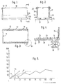
- a container 10 of rectangular shape made of sheet steel has on one side, preferably an end face, a fitting, for example a threaded connector 11, which is firmly inserted, for example screwed, into an upper opening of the container 10.
- the fitting has a flange 12 for connection to a hose, not shown.
- the valve 11 can be sealed to the container opening by one or more sealing rings made of polytetrafluoroethylene or rubber.
- a connection element for example also a flange of the hose which conveys the sludge into the container 10 with the aid of a pump, is connected to the flange 12.
- the pump (not shown) is an eccentric screw pump, diaphragm pump or a pressure hose pump, the latter being provided with a component which intermittently acts on a hose wall with a squeezing effect, for example rotating rollers.
- the container 10 has one or more fittings 14, 15 in the region of the bottom 13 for draining off the filtrate.
- the drain fittings are designed as cone or slide valves.
- At least one flexible rubber 0-ring seal or the like can be inserted between the container wall and the fitting neck.
- the container 10 designed as a pressure container can have a lid.
- the container is preferably provided on the bottom 13 with rails 20, which can be steel profile parts. These serve as sliding components in order to slide the container 10 onto a supporting floor 21 of a truck, a semi-trailer or even a transport barge or ship. Instead of the rails 20, equivalent, friction-reducing components, such as rollers or rollers, can be used, depending on the individual case.
- the transport vehicle known as such is not shown.
- the filter element 23, the protective net 24, the coarse net 25 extends (as only indicated) along the inner surface of the side walls 17, 18 and the other walls.
- the filter element can also be a fine sieve.
- the filtrate is drained off via the outlet connection 14 or 15 via a drain valve 28 controlled by a pressure manometer 27.
- the pressure gauge 27 can be set to an overpressure of 0.3 to 1.2 bar or higher, depending on the design of the container as a pressure container .
- the manometer 27 can also be connected via a control or control line (not shown) to the pump connected to the fitting 11 and conveying the sludge into the container 10.
- the pressure-time diagram according to FIG. 5 shows an embodiment according to the invention for loading the container 10 with the sludge to be filtered. This shows the intermittent variant. After a gradual, here linear pressure increase in curve branch a, valve 28 opens at time t1, the filtrate is drained off, and this results in a pressure drop according to branch b.
- the method according to the invention makes it possible to increase the efficiency of the dewatering, depending on the type of sludge, the construction of the container, the desired puncture resistance or another operating characteristic of the cake and / or filtrate.
- the non-linear pressure increase in the container, curve c can increase the possible effects on cake and / or filtrate throughput.
- This can also be done by means of a pulse-like pressure curve, curve d, or by intermittently increasing the sludge supply into the container 16, curve b. In individual cases, the advantageous effect on cake and filtrate is increased by this pressure build-up being carried out in different periods of time or pressure.
Landscapes
- Chemical & Material Sciences (AREA)
- Chemical Kinetics & Catalysis (AREA)
- Engineering & Computer Science (AREA)
- Environmental & Geological Engineering (AREA)
- Life Sciences & Earth Sciences (AREA)
- Hydrology & Water Resources (AREA)
- Mechanical Engineering (AREA)
- Water Supply & Treatment (AREA)
- Organic Chemistry (AREA)
- Treatment Of Sludge (AREA)
- Extraction Or Liquid Replacement (AREA)
- Organic Low-Molecular-Weight Compounds And Preparation Thereof (AREA)
- Pharmaceuticals Containing Other Organic And Inorganic Compounds (AREA)
- Steroid Compounds (AREA)
Abstract
Description
Die Erfindung bezieht sich auf ein Verfahren und eine Vorrichtung zur Ausscheidung von Flussigkeiten aus heterogenen Flüssigkeitsfeststoffgefügen als Entwässerungs- bzw. Eindickverfahren für kommunale oder industrielle Schlämme, bei dem in einen Behälter Schlamm bei einem niedrigen und danach bei einem relativ höheren Druck zugepumpt wird und aus dem Behälterdruckraum bzw. einem Schlammkuchen innerhalb des Behälters ein Filtrat abgezogen wird.The invention relates to a method and an apparatus for separating liquids from heterogeneous liquid solid structures as a dewatering or thickening process for municipal or industrial sludges, in which sludge is pumped into a container at a low and then at a relatively higher pressure and from which Container pressure space or a mud cake within the container, a filtrate is withdrawn.
Solche Schlämme fallen in der Kanalisation von Gemeinden und Städten sowie bei verschiedenen Industriebetrieben seit Jahren in wachsender Anzahl an. Bevor diese Schlämme in wirtschaftlicher Weise zu Deponien befördert bzw. überhaupt einer Nachbehandlungsstufe ausgesetzt werden, um den Schlämmen eine deponiefähige Konsistenz zu geben, werden die Schlämme mehr oder weniger entwässert.Such sludges have been accumulating in sewers in municipalities and cities as well as in various industrial companies for years. Before these sludges are economically transported to landfills or even subjected to a post-treatment stage in order to give the sludges a consistency that can be landfilled, the sludges are more or less dewatered.
Hierzu gehören auch Rieselfelder, Schlammabsetzteiche und Schlammtrockenbeete, deren Anlage, Wartung und Räumung allerdings zeitaufwendig und lohnintensiv ist.This also includes trickle fields, sludge settling ponds and sludge dry beds, the installation, maintenance and clearing of which, however, is time-consuming and labor-intensive.
Bekannte Verfahren nach dem Prinzip der Schwerkraftfiltration ermöglichen nur eine begrentze Entwässerungsleistung, aber nicht, die für den Schlammkuchen erforderliche gute Stichfestigkeit zu erreichen, deren Güte für eine Ablagerung auf Deponien unumgänglich ist und die bei einem Einlauffeststoffgehalt im Dünnschlamm ab ca. 15% TS (absolute Trockensubstanz) erreicht ist. (GB-A Nr. 153335, US-A Nrn. 1537818, 3317047, DE-U Nr. 1975690 und DE-C Nr. 2320350.)Known methods based on the principle of gravity filtration only allow a limited drainage performance, but not to achieve the good puncture resistance required for the sludge cake, the quality of which is unavoidable for deposition on landfills and which with an intake solids content in the thin sludge from approx. 15% TS (absolute Dry matter) is reached. (GB-A No. 153335, US-A No. 1537818, 3317047, DE-U No. 1975690 and DE-C No. 2320350.)
Gemäss letzterer DE-PS Nr. 2320350 sind bereits transportierbare Behälter mit schrägen siebartigen Entwässerungswänden bekannt, bei denen diese Wände durch eine Stützkonstruktion im Abstand zu den geschlossen ausgebildeten Behälterwänden gehalten sind. Allerdings ist auch hier die Entwässerungsleistung durch das Prinzip der Schwerkraftfiltration vorgegeben und entsprechend beschränkt.According to the latter DE-PS No. 2320350, transportable containers with inclined sieve-like drainage walls are already known, in which these walls are held at a distance from the closed container walls by a support structure. However, the drainage capacity is also predetermined and limited accordingly by the principle of gravity filtration.
Bekannte Verfahren sind auch insoweit verbesserungsbedürftig, als sie nur Schlammengen bis maximal ca. 10 m3/h in einen offenen Behälter oder Filtersack im Zulauf einzubringen gestatten. Aus der Praxis ergeben sich dann zumeist noch geringere Einlaufmengen, da die Schlammwucht die Poren oder Filtersieböffnung in kurzer Zeit verschliesst und eine Flüssigkeitsableitung weitgehend verhindert, zum anderen nur eine Füllgrösse zulässt, die durch eine Gegenprallwirkung, in Abhängigkeit von der Höhe des Behälters, weitgehend beeinflusst wird.Known methods are also in need of improvement insofar as they only allow sludge quantities of up to a maximum of approximately 10 m 3 / h to be introduced into an open container or filter bag in the inlet. In practice, there are usually even lower intake quantities because the sludge balances the pores or filter screen opening in a short time and largely prevents liquid drainage, and on the other hand only allows a filling size that is largely influenced by a counter-impact effect, depending on the height of the container becomes.
So können in der Praxis lediglich zur Entwässerung dienende Behälter bzw. Container bis zu ca. 2,0 m Höhe und 4,0 m obere Kantelänge - die Breite wird durch die Bodenabmessungen des Lastkraftwagens eingegrenzt - eingesetzt werden. In etwa können Dünnschlammengen bis 40 m3 innerhalb 5 bis 7h in einen 12-m3-Entwäs- serungscontainer eingebracht und bis gerade zur beginnenden Stichfestigkeit nach ca. 12 h entwässert werden. Hierbei ist die Konstanz noch immer gelartig bis dickbreiähnlich. Die Schwerkraft bei 2 m Füllhöhe ergibt in Bodenhöhe eine derartige Verdickung, dass die nach 12 bis 20 h noch minimale Abtropfmenge auf die gesamte Entwässerungsleistung, insbesondere auf die Stichfestigkeit des Schlammkuchens, kaum einen Einfluss zeigt.In practice, only containers or containers up to approx. 2.0 m high and 4.0 m upper edge length can be used for drainage - the width is limited by the floor dimensions of the truck. Approximately, thin sludge quantities of up to 40 m 3 can be placed in a 12 m 3 drainage container within 5 to 7 hours and dewatered until the puncture resistance begins after about 12 hours. The constancy is still gel-like to porridge-like. Gravity at a filling height of 2 m results in such a thickening at ground level that the minimal amount of dripping after 12 to 20 hours has hardly any influence on the overall drainage performance, in particular on the puncture resistance of the mud cake.
Zwar sind bereits ein Verfahren und zugehörige Vorrichtung bekannt, um biologische bzw. aerobische Schlämme in eine Flüssigkeit (Filtrat) und feste Schlammbestandteile zu trennen, bei dem in einem geschlossenen Behälter mit Überdruck gearbeitet wird. Allerdings soll hier unter einer Zwischenschicht ein Schlammkonzentrat und über der Zwischenschicht das Filtrat sich bilden und ferner das Filtrat vertikal nach oben, das Schlammkonzentratvertikal nach unten abgezogen werden. Hier wirkt die Schwerkraft des Filtrates entgegen seiner Abzugrichtung, unterstützt das letztere somit nicht. Die Einwirkung des Überdruckes bezwecktvorallem die Bildung derZwischenschicht, des Überdruck wirkt nicht ständig auf ein Filtratschlammfestkörperchengemisch ein. Für die Absonderung des Schlammes als Trockensubstanz sind nicht die üblichen Siebe vorgesehen. Es wird kontinuierlich gearbeitet; sofern eine unterbrochene (intermittierende) Arbeitsweise für die Behandlung des Schlammes vorgesehen ist, soll der Filtratabzug entfallen. Der zugehörige Behälter ist stationär mit aus Beton bestehendem zylindrischem Körper mit vertikaler Achse hergestellt, so dass ein Filtratabzug im unteren Bereich, wie bei fahrbaren Behältern üblich, nicht nahegelegt ist. Mittel zur Entnahme des Schlammkuchens sind nicht angegeben (CH-A Nr. 379417).A method and associated device are already known for separating biological or aerobic sludges into a liquid (filtrate) and solid sludge constituents, in which overpressure is used in a closed container. However, a sludge concentrate should form here under an intermediate layer and the filtrate should form above the intermediate layer and furthermore the filtrate should be drawn off vertically upwards, the sludge concentrate vertically downwards. Here the gravity of the filtrate acts counter to its withdrawal direction, so it does not support the latter. The effect of the overpressure primarily aims at the formation of the intermediate layer, the overpressure does not constantly act on a filtrate sludge solid mixture. The usual screens are not provided for the separation of the sludge as dry matter. It is worked continuously; if there is an intermittent (intermittent) procedure for the treatment of the sludge, the filtrate discharge should be omitted. The associated container is made stationary with a cylindrical body made of concrete with a vertical axis, so that a filtrate discharge in the lower area, as is customary with mobile containers, is not suggested. Means for removing the mud cake are not specified (CH-A No. 379417).
Bei einem anderen bekannten Filtrationsverfahren wird der sich auf Filterflächen ansammelnde Schlamm, teilweise in Förderrichtung, ausser der Schwerkraft einem Gasdruck ausgesetzt. Allerdings ist hier die Art der Druckverteilung nicht genauer angegeben, soll aber ein stetig steigender Druckzustand sein. Es kann aber auch mit konstantem Unterdruck gearbeitet werden. Allerdings handelt es sich um einen stationären Schlammverdichter aufwendiger Bauart, bei welchem auch Rührer bzw. schneckenartige Schlammverdichter mit Antrieb notwendig sind. Das bekannte Verfahren ist für Dünnschlämme bzw. biologische Schlämme schon aus diesem Grunde nicht oder nur durch besondere Flockenmittelzugabe einsetzbar (DE-A Nr. 2217558).In another known filtration method, the sludge accumulating on filter surfaces is exposed to gas pressure, partly in the direction of conveyance, apart from gravity. However, the type of pressure distribution is not specified here, but should be a steadily increasing pressure condition. However, it is also possible to work with constant negative pressure. However, it is a stationary sludge compactor of complex design, in which stirrers or screw-type sludge compactors with drive are also necessary. For this reason alone, the known method cannot be used for thin sludges or biological sludges, or only by adding special flocculants (DE-A No. 2217558).
Ein bekanntes Filtrierverfahren dient zum Auspressen vor Klärschlämmen mit Hilfe von Kammerfilterpressen (DE-A Nr. 2750028). Hierwird in der Regel mit einem oberen und einem unteren Grenzdruckwert gearbeitet. Der obere Druckgrenzwert dient dazu, einen möglichst hohen Feststoffgehalt in einem ausgepressten Schlammkuchen zu erzielen. Diese Druckgrenzwerte werden nicht unmittelbar, sondern über Aniaufpressphasen erreicht. Diesen schliesst sich eine Vielzahl von Presszyklen an, bei denen gleichzeitig Schlamm den Kammern wieder zugeführt wird. Hierdurch soll der Druck schrittweise erhöht werden. Es ist hierbei bekannt, beim Übergang von der einen auf die andere Pressphase den Kammerdruck abzusenken, z.B. um 1 bar, sowie zwischen der Nachbeschickungsphase und der Endpressphase mit einer Zeitverzögerung von 6 ± 2 min zu arbeiten. Dem auszupressenden Nassschlamm kann Kalk (CaO) oder Kalkmilch zugesetzt werden, und man überwacht durch Druckfühler, ob der obere bzw. untere Grenzwert erreicht wird, um 'dann durch ein Steuersignal die Förderpumpe entsprechend zu- bzw. abzuschalten. Die Grenzwerte sind somit einstellbar, und die Vorrichtung ist ferner mit einem Zyklenzähler für die Pressphasen oder mit dem Druckfühler gekoppelten Verzögerungsgliedern versehen. Die Pressenkammern sind auch über Ventile an der Saugseite einer Vakuumpumpe anschliessbarA known filtering method is used for pressing out of sewage sludge with the help of chamber filter presses (DE-A No. 2750028). As a rule, an upper and a lower limit pressure value are used here. The upper pressure limit serves to achieve the highest possible solids content in a pressed out mud cake. These pressure limit values are not reached directly, but rather via the press-on phases. This is followed by a large number of pressing cycles in which sludge is fed back into the chambers at the same time. This is supposed to pressure be gradually increased. It is known here to lower the chamber pressure during the transition from one to the other pressing phase, for example by 1 bar, and to work with a time delay of 6 ± 2 min between the refilling phase and the final pressing phase. The pressing out of slurry may be added to lime (CaO) or lime milk, and is monitored by pressure sensor whether the upper or lower limit is reached, then supply 'by a control signal corresponding to the feed pump on and off. The limit values can thus be set, and the device is also provided with a cycle counter for the pressing phases or with delay elements coupled to the pressure sensor. The press chambers can also be connected via valves on the suction side of a vacuum pump
Allerdings handelt es sich bei einer Kammerfilterpresse um eine stationäre Maschine, bei der eine Vielzahl von einzelnen hintereinander angeordneten Presskammern, die zwischen einem feststehenden Pressentisch und einem beweglichen, stempelartigen Pressenkopf lösbar, aber fest eingespannt sind, eine Art Plattenstapel bilden. Eine Einwirkung der Schwerkraft auf den Filtriervorgang ist hier ganz unerheblich. Es wird zwangsläufig, besonders in der Druckenphase, mit ausserordentlich hohen, mindestens 12 bar betragenden Drücken gearbeitet.However, a chamber filter press is a stationary machine in which a multiplicity of individual press chambers arranged one behind the other, which are detachable but firmly clamped between a fixed press table and a movable, stamp-like press head, form a type of plate stack. The influence of gravity on the filtering process is completely irrelevant here. It is inevitable, especially in the printing phase, to work with extraordinarily high pressures of at least 12 bar.
Bei einem bekannten Filtrierverfahren werden Filterpressen eingesetzt. Hier wird zwar in der Leitung zwischen Pumpe und Presse ein Überdruck aufgebaut. Filterpressen, nämlich Kammerfilterpressen oder Schraubenverdichter, sind jedoch schwere Maschinen und nur schlecht an transportablen Behältern und zugehörigen Fahrzeuge installierbar. Ferner kann bei biologischen Dünnschlämmen keine mit Hochdruck arbeitende Schlammpumpe bzw. Filterpresse deshalb eingesetzt werden, weil bei letzteren Schlämmen bekanntlich bei relativ niedrigen Drucken gearbeitet werden muss, deshalb, weil der Dünnschlamm zart strukturiert ist, bei biologischen Schlämmen ganz überwiegend aus Bakterien besteht und diese auch schon bei einem Rührvorgang, geschweige beim Hochdruck, aufplatzen und somit das Absetzvolumen sich in kurzer Zeit nachteiligerweise vergrössert. Volumenvergrösserungen von 50 bis 60% innerhalb weniger Minuten sind bekannt. Das bekannte Verfahren eignet sich somit nicht für Dünnschlämme nach dem Oberbegriff des Anspruches 1 (DE-A Nr. 1461443).In a known filtration process, filter presses are used. Here, an overpressure is built up in the line between the pump and the press. However, filter presses, namely chamber filter presses or screw compressors, are heavy machines and are difficult to install on transportable containers and associated vehicles. Furthermore, biological thin sludge cannot be operated with a high-pressure sludge pump or filter press because, as is well known, the latter sludge has to be operated at relatively low pressures, because the thin sludge is delicately structured, biological sludges consist predominantly of bacteria and these too Even during a stirring process, let alone high pressure, it bursts open and the sedimentation volume increases disadvantageously in a short time. Volume increases of 50 to 60% within a few minutes are known. The known method is therefore not suitable for thin sludges according to the preamble of claim 1 (DE-A No. 1461443).
Der Erfindung liegt die Aufgabe zugrunde, die Entwässerungsleistung, d.h. den Filtratabzug, pro Zeiteinheit, bei Verwendung einfacher mit Filtergeweben oder Feinsieben versehenertransportabler Entwässerungsbehälter, insbesondere bei transportablen Dünnschlammbehältern, wesentlich zu erhöhen.The object of the invention is to improve the drainage capacity, i.e. to significantly increase the filtrate discharge per unit of time when using simple transportable drainage tanks provided with filter fabrics or fine sieves, especially with portable thin sludge tanks.
Diese Aufgabe löst die Erfindung so, wie sie in den Ansprüchen gekennzeichnet ist.This object is achieved by the invention as characterized in the claims.
Die durch die Erfindung erreichten Vorteile bestehen darin, dass nunmehr heterogene Flüssigkeitsfeststoffgefüge, insbesondere Dünnschlämme, schneller als bisher filtriert werden und, je nach Art des Schlammes, auch im Einzelfall eine Vortrocknung erfotge'i kann. Sie ist insbesondere für mit Lastkraftwagen transportierbare Behälter anwendbar, wobei die vorrichtungsmässige Anpassung des Behälters billig ist. Ein weiterer Vorteil besteht darin, dass nun erstmals Grossraumcontainer als Entwässerungsbehälter nutzbar gemacht werden können, einschliesslich von durch Schiffe transportablen Containern, weil durch den wesentlich erhöhten Filtratentzug für die Grosscontainer die erforderliche Wirtschaftlichkeit erreicht wird. Der Grossraumcontainer kann auch in Gleitrahmenbauart und/oder als Sattelschlepper Auflieger od. dgl. eingesetzt werden, je nach der einzeln zweckmässigen Transportart. Es können auch Rundbehälter mit allseitig geschlossener Bauform eingesetzt werden.The advantages achieved by the invention are that now heterogeneous liquid solid structure, in particular thin sludges, are faster than before, and filtered, depending on the nature of the sludge, erfotge predrying in individual cases' i can. It can be used in particular for containers which can be transported by truck, the adaptation of the container in terms of device being inexpensive. Another advantage is that now for the first time large containers can be used as drainage containers, including containers that can be transported by ship, because the significantly increased filtrate removal for the large containers achieves the required economy. The large-capacity container can also be used in the form of a sliding frame and / or as a semi-trailer or the like, depending on the individually appropriate mode of transport. Round containers with a closed design on all sides can also be used.
Im folgenden wird die Erfindung anhand von lediglich einen Ausführungsweg darstellenden Zeichnungen näher erläutert. Es zeigt:
- Fig. 1 einen Behälter mit einem schematisch dargestellten Einflussstutzen und einem Stutzen für Filtratabfluss,
- Fig. 2 einen Schnitt nach Linie A-A der Fig. 1,
- Fig. 3 eine Draufsicht auf Fig. 1, wobei die obere Wandung entfernt ist,
- Fig. 4 eine vergrösserte Darstellung eines Eckbereichs des Behälters, markiert in Fig. 3 mit B, und
- Fig. 5 ein Druck-Zeit-Diagramm für einen Ausführungsweg der Druckverteilung im Behälter während des Betriebes.
- 1 shows a container with a schematically illustrated inlet connection and a connection for filtrate outflow,
- 2 shows a section along line AA of FIG. 1,
- 3 is a top view of FIG. 1 with the top wall removed;
- Fig. 4 is an enlarged view of a corner region of the container, marked in Fig. 3 with B, and
- Fig. 5 is a pressure-time diagram for an embodiment of the pressure distribution in the container during operation.
Ein aus Stahlblech bestehender Behälter 10 von rechteckiger Form (vgl. Fig. 1) weist an einer Seite, vorzugsweise einer Stirnseite, eine Armatur, z.B. einen Gewindestutzen 11 auf, der in eine obere Öffnung des Behälters 10 fest eingesetzt, z.B. verschraubt wird. Die Armatur weist einen zum Anschluss für einen nicht dargestellten Schlauch vorhandenen Flansch 12 auf. Zur Behälteröffnung kann die Armatur 11 durch einen oder mehrer Dichtringe aus Polytetrafluoräthylen oder Kautschuk abgedichtet sein. An den Flansch 12 wird ein Anschlusselement, z.B. ebenfalls ein Flansch des den Schlamm in den Behälter 10 mit Hilfe einer Pumpe fördernden Schlauches, angeschlossen. Die (nicht dargestellte) Pumpe ist eine Exzenterschneckenpumpe, Membanpumpe oder eine Druckschlauchpumpe, wobei letztere mit intermittierend an einer Schlauchwandung mit Quetschwirkung angreifende Bauelement, z.B. umlaufende Rollen, versehen ist. Der Behälter 10 hat im Bereich des Bodens 13 eine oder mehrere Armaturen 14,15 zum Ablassen des Filtrats. Die Ablassarmaturen sind in ihrer einfachsten Bauweise als Kegel- oder Schieberventile ausgebildet. Zwischen Behälterwandung und Armaturhals kann mindestens eine nachgiebige 0-Ringdichtung aus Kautschuk od. dgl. eingesetzt sein. Der als Druckbehälter ausgebildete Behälter 10 kann einen Deckel aufweisen. Zwischen der oberen Stirnkante der Seitenwände 17, 18 und der Innenfläche des Dekkels kann eine umlaufende Profildichtung aus Kautschuk oder, bei aggressiveren Schlämmen, aus Polytetrafluoräthylen dichtend im Randbereich eingesetzt sein. Des Behälter ist vorzugsweise am Boden 13 mit Schienen 20 versehen, die Stahlprofilteile sein können. Diese dienen als Gleitbauteile, um den Behälter 10 auf einen tragenden Boden 21 eines Lastkraftwagens, eines Sattelschleppers oder auch eines Transportkahnes bzw. -schiffes gleitend aufzuschieben. Statt der Schienen 20 können äquivalente, die Reibung verringernde Bauteile, wie Rollen oder Walzen, je nach Einzelfall, benutzt werden. Das als solches bekannte Transportfahrzeug ist nicht dargestellt.A
Sofern Behälter 10 mit einer abnehmbaren Wand, insbesondere dem Deckel, gebaut wird, sind im Bereich der Kanten oder Ecken (vgl. Fig. 2) zwischen Deckel und den Stirnwänden und/oder den Seitenwänden 17, 18 mechanische, manuell betätigbare Verschlüsse 32 vorhanden, z.B. Spann-, Haken-, Scharnierverschlüsse. Hier greift z.B. eine an einem Kniehebel vorhandede Öse, befestigt an der Seitwand 17 bzw. 18 in ein am Dekkel starr befestigtes Maul oder einen Haken, ein. Die Dicke und/oder Anordnung der Behälterwände ist nach einer Ausführungsform der Erfindung so ausgelegt, dass sie bei dem zu erwartenden Höchstüberdruck in Behälter, der bei 4,4 bar liegen kann, zuzüglich eines aus der Wöhlerkurve bekannten Sicherheitskoeffizienten für die Dauerbelastung eines Metalles, vollständig ausserhalb einer Rissgefahr liegen. Ferner können verstärkende Segmente, wie Rippen oder Stege, über den Dekkel bzw. den Boden 13 als auch über die Seitenwände geführt und festgemacht sein, z.B. Rippen 22 in Fig. 3. Solche Stützelemente können die gesamte Wandhöhe ausnutzen. Vorzugsweise bilden solche Stützelemente an den Längsseiten der Wände im Inneren des Behälters zugleich Abstandshalter, die eine Tragkonstruktion aus einem ausreichend stark dimensionierten Lochblech und/oder einer starren, kräftigen Drahtgitterunterlage darstellen. Dies ist in Fig. 4 dargestellt. Hier ist das eigentliche Filterelement 23 (Gewebewand oder ein Polymergitter) dargestellt. Das Filterelement 23 kann am oberen Ende überstehend ausgebildet und an der Wand anliegend und mit einer Abdichtung gegen evt. aufspritzende Schlämme und/oder sonstige zu entwässernde feststoffhaltige Flüssigkeiten ausgebildet sein. Dieses Element 23 kann auch an einer Versteifungswinkelkonstruktion 24 anliegend angeordnet sein. Erfindungsgemäss ist es vorteilhaft, das Filterelement 23 in gesamter Länge und bis auf die obere Umbiegekante desselben auch in der Höhe mit einer groben Schutznetzkonstruktion zu bedecken. In Fig. 4 ist das Schutznetz 24 schematisch dargestellt. Unter dem Filterelement 23 befindet sich eine Tragkonstruktion für dieses in Form eines Lochbleches oder Grobgitters 25. Zwischen dem Boden 13 und dem Grobgitter 25 angeordnete Halteelemente 26 dienen als Abstandshalter für das Filterelement 23. Diese Halteteile 26 sind gemäss Erfindung gleichzeitig als Stütz- und Versteifungselemente für die Behälterwände vorgesehen.If
Die Anordnung des Filterelementes 23, des Schutznetzes 24, des Grobnetzes 25 erstreckt sich (wie nur angedeutet) weiter entlang der Innenfläche der Seitenwände 17, 18 und der anderen Wände. Das Filterelement kann ausser einem Filtergewebe auch ein Feinsieb sein.The arrangement of the
Das Ablassen des Filtrats über den Ablaufstutzen 14 oder 15 erfolgt über durch ein Druckmanometer 27 gesteurtes Ablaufventil 28. Das Manometer 27 kann auf einen Überdruck von 0,3 bis 1,2 bar, oder höher, je nach Auslegung des Behälters als Druckbehälter, eingestellt sein. Auch kann das Manometer 27 über eine nicht dargestellte Steuer- oder Regelleitung mit der an der Armatur 11 angeschlossenen, den Schlamm in den Behälter 10 fördernden Pumpe in Verbindung stehen. In dem Druck- Zeit-Diagramm gemäss Fig. 5 ist ein erfindungsgemässer Ausführungsweg für die Beschickung des Behälters 10 mit dem zu filtrierenden Schlamm dargestellt. Diese zeigt die intermittierende Ausführungsvariante. Nach einem allmählichen, hier linearen Druckanstieg im Kurvenzweig a erfolgt zum Zeitpunkt t1 das Öffnen des Ventils 28, das Filtrat wird abgelassen und hieraus ergibt sich ein Druckabfall gemäss Zweig b. Dieser Ablauf wiederholt sich sinngemäss für die weitere Betriebszeit. Der in Fig. 1 angedeutete Schlammkuchen 29, der später durch eine verschliessbare Klappe 30 od. dgl. abführbar ist, gibt somit in jedem Arbeitszyklus ein a-t1-b-Filtrat ab, bzw. der sich entwässernde Kuchen vergrössert sich nacheinander in vertikaler Richtung.The filtrate is drained off via the
Das erfindungsgemässe Verfahren gestattet, die Effizienz der Entwässerung zu steigern, in Abhängigkeit von der Art des Schlammes, der Bauweise des Behälters, der erwünschten Stichfestigkeit oder einer anderen Betriebseigenschaft des Kuchens und/oder Filtrats. Dies kann durch quadratisch ansteigende (nicht dargestellt) Druckkurvenwerte erreicht werden. In dem Zweig bis zum Punkt t1 erfolgt zunächst der Druckanstieg geringer, danach aber wesentlich steiler, etwa nach der Formel b=f (t2). Es ist erkannt worden, dass durch nicht linearen Druckanstieg im Behälter, Kurve c, die Einwirkungsmöglichkeiten auf Kuchen und/ oder Filtratdurchsatz vergrössert werden können. Dies kann auch durch einen impulsartigen Druckverlauf, Kurve d, bzw. durch stossweise Erhöhung der Schlammzufuhr in den Behälter 16 erfolgen, Kurve b. Im Einzellfall vergrössert sich die vorteilhafte Einwirkung auf Kuchen und Filtrat, indem dieser Druckaufbau in unterschiedlich langen Zeit- bzw. Druckperioden durchgeführt wird.The method according to the invention makes it possible to increase the efficiency of the dewatering, depending on the type of sludge, the construction of the container, the desired puncture resistance or another operating characteristic of the cake and / or filtrate. This can be achieved by increasing the pressure curve (not shown) by a square. In the branch up to point t1, the pressure rise initially occurs less, but then much steeper, for example according to the formula b = f (t 2 ). It has been recognized that the non-linear pressure increase in the container, curve c, can increase the possible effects on cake and / or filtrate throughput. This can also be done by means of a pulse-like pressure curve, curve d, or by intermittently increasing the sludge supply into the container 16, curve b. In individual cases, the advantageous effect on cake and filtrate is increased by this pressure build-up being carried out in different periods of time or pressure.
Claims (6)
Priority Applications (7)
| Application Number | Priority Date | Filing Date | Title |
|---|---|---|---|
| EP81100792A EP0057732B1 (en) | 1981-02-05 | 1981-02-05 | Method and apparatus for the separation of liquids from heterogeneous liquid-solid material mixtures, e.g. methods for the dehydration or thickening of communal or industrial sludges |
| DE8181100792T DE3165144D1 (en) | 1981-02-05 | 1981-02-05 | Method and apparatus for the separation of liquids from heterogeneous liquid-solid material mixtures, e.g. methods for the dehydration or thickening of communal or industrial sludges |
| AT81100792T ATE8769T1 (en) | 1981-02-05 | 1981-02-05 | METHOD AND DEVICE FOR SEPARATING LIQUIDS FROM HETEROGENEOUS LIQUID MASS VESSELS, FOR EXAMPLE DRAINAGE RESPECTIVELY. THICKENING PROCESS FOR MUNICIPAL OR INDUSTRIAL SLUDGE. |
| DK145681A DK149305C (en) | 1981-02-05 | 1981-03-31 | METHOD AND APPARATUS FOR SEPARATING LIQUIDS FROM THE HETEROGENIC LIQUID MASS STRUCTURES, e.g. BY DRAINAGE OR THICKENING METHODS FOR COMMUNAL OR INDUSTRIAL SLUDGE |
| FI813416A FI73955C (en) | 1981-02-05 | 1981-10-30 | FOERFARANDE OCH ANORDNING FOER AVSKILJNING AV VAETSKOR UR HETEROGENA STRUKTURER AV VAETSKOR OCH FAST MATERIAL, SAOSOM URVATTNINGS- ELLER FOERTJOCKNINGSFOERFARANDE FOER KOMMUNALT ELLER INDUSTRIELLT SLAM. |
| NO814313A NO155436C (en) | 1981-02-05 | 1981-12-16 | PROCEDURE AND APPARATUS FOR THE SEPARATION OF LIQUIDS FROM THE HETEROGENIC LIQUID / SOLID MIXTURES, INTENDED TO DETAIL OR CONCENTRATE COMMUNAL OR INDUSTRIAL SLUES. |
| BE0/209321A BE894798A (en) | 1981-02-05 | 1982-10-25 | PROCESS AND DEVICE FOR SEPARATING LIQUIDS OF HETEROGENEOUS STRUCTURES FOR DEHYDRATION OR THICKENING OF SLUDGE |
Applications Claiming Priority (1)
| Application Number | Priority Date | Filing Date | Title |
|---|---|---|---|
| EP81100792A EP0057732B1 (en) | 1981-02-05 | 1981-02-05 | Method and apparatus for the separation of liquids from heterogeneous liquid-solid material mixtures, e.g. methods for the dehydration or thickening of communal or industrial sludges |
Publications (2)
| Publication Number | Publication Date |
|---|---|
| EP0057732A1 EP0057732A1 (en) | 1982-08-18 |
| EP0057732B1 true EP0057732B1 (en) | 1984-08-01 |
Family
ID=8187560
Family Applications (1)
| Application Number | Title | Priority Date | Filing Date |
|---|---|---|---|
| EP81100792A Expired EP0057732B1 (en) | 1981-02-05 | 1981-02-05 | Method and apparatus for the separation of liquids from heterogeneous liquid-solid material mixtures, e.g. methods for the dehydration or thickening of communal or industrial sludges |
Country Status (7)
| Country | Link |
|---|---|
| EP (1) | EP0057732B1 (en) |
| AT (1) | ATE8769T1 (en) |
| BE (1) | BE894798A (en) |
| DE (1) | DE3165144D1 (en) |
| DK (1) | DK149305C (en) |
| FI (1) | FI73955C (en) |
| NO (1) | NO155436C (en) |
Cited By (1)
| Publication number | Priority date | Publication date | Assignee | Title |
|---|---|---|---|---|
| AT384010B (en) * | 1984-05-28 | 1987-09-25 | Voest Alpine Ag | METHOD FOR DRAINING SLUDGE AND / OR ORGANIC SUBSTANCES |
Families Citing this family (2)
| Publication number | Priority date | Publication date | Assignee | Title |
|---|---|---|---|---|
| FR2696954A1 (en) * | 1992-10-20 | 1994-04-22 | Inst Textile De France | Storage device and sludge detoxification installation. |
| US8476794B2 (en) * | 2009-05-27 | 2013-07-02 | Empire Technology Development Llc | Wheel motor with rotating outer rotor |
Citations (1)
| Publication number | Priority date | Publication date | Assignee | Title |
|---|---|---|---|---|
| DE2750028A1 (en) * | 1977-11-09 | 1979-05-10 | Rolf Flach | METHOD FOR EXPRESSION OF CLAIMS AND DEVICE FOR CARRYING OUT THE METHOD |
Family Cites Families (3)
| Publication number | Priority date | Publication date | Assignee | Title |
|---|---|---|---|---|
| GB934487A (en) * | 1959-08-21 | 1963-08-21 | Griffin Rhodesia Pvt Ltd | Improvements in or relating to the separation of the liquid and solid constituents of sludges |
| DE1461443C3 (en) * | 1963-10-21 | 1973-09-13 | Passavant-Werke Michelbacher Huette, 6209 Aarbergen | Process for filtering, in particular for dewatering sewage sludge |
| DE2217558A1 (en) * | 1972-04-12 | 1973-10-18 | Nemetz & Ruess Klaeranlagen | Digested sludge filter cone - with thickening action by revolving inner cone with helical turns |
-
1981
- 1981-02-05 EP EP81100792A patent/EP0057732B1/en not_active Expired
- 1981-02-05 DE DE8181100792T patent/DE3165144D1/en not_active Expired
- 1981-02-05 AT AT81100792T patent/ATE8769T1/en not_active IP Right Cessation
- 1981-03-31 DK DK145681A patent/DK149305C/en not_active IP Right Cessation
- 1981-10-30 FI FI813416A patent/FI73955C/en not_active IP Right Cessation
- 1981-12-16 NO NO814313A patent/NO155436C/en unknown
-
1982
- 1982-10-25 BE BE0/209321A patent/BE894798A/en not_active IP Right Cessation
Patent Citations (1)
| Publication number | Priority date | Publication date | Assignee | Title |
|---|---|---|---|---|
| DE2750028A1 (en) * | 1977-11-09 | 1979-05-10 | Rolf Flach | METHOD FOR EXPRESSION OF CLAIMS AND DEVICE FOR CARRYING OUT THE METHOD |
Cited By (1)
| Publication number | Priority date | Publication date | Assignee | Title |
|---|---|---|---|---|
| AT384010B (en) * | 1984-05-28 | 1987-09-25 | Voest Alpine Ag | METHOD FOR DRAINING SLUDGE AND / OR ORGANIC SUBSTANCES |
Also Published As
| Publication number | Publication date |
|---|---|
| DK149305C (en) | 1986-09-08 |
| FI73955C (en) | 1987-12-10 |
| NO814313L (en) | 1982-08-06 |
| DK149305B (en) | 1986-04-28 |
| FI813416L (en) | 1982-08-06 |
| EP0057732A1 (en) | 1982-08-18 |
| ATE8769T1 (en) | 1984-08-15 |
| FI73955B (en) | 1987-08-31 |
| DE3165144D1 (en) | 1984-09-06 |
| BE894798A (en) | 1983-04-25 |
| NO155436B (en) | 1986-12-22 |
| DK145681A (en) | 1982-08-06 |
| NO155436C (en) | 1987-04-01 |
Similar Documents
| Publication | Publication Date | Title |
|---|---|---|
| DE69826514T2 (en) | A MOBILE UNIT AND A METHOD FOR THE CLEANING OF MUD AND WASTE WATER | |
| DE69427874T2 (en) | Plant and method for filtering and thickening sludge | |
| WO1988003048A1 (en) | Process and installation for dewatering waste water sludge | |
| DE1436296A1 (en) | Filter press | |
| DE1172201B (en) | Pressure filter press and method for dewatering wet, fine-grained material, such as coal sludge and the like. like | |
| DE2320350C3 (en) | Device for dewatering and transporting sludge or the like. Crowds | |
| DE2750028C2 (en) | ||
| DE4013786C2 (en) | ||
| EP0264899A2 (en) | Dehydration device for muds and similar products | |
| DE3234560A1 (en) | FILTER DEVICE, ESPECIALLY FOR BEVERAGES | |
| EP2223723A1 (en) | Method and device for separating liquid | |
| DE10207451A1 (en) | Device and method for dewatering sludge | |
| DE4300709C2 (en) | Method for disposing of waste water from a motor vehicle car wash and device for carrying out the method | |
| DE2738239A1 (en) | DEVICE FOR THE PRODUCTION OF SHAPED BODIES, IN PARTICULAR ORE PELLETS FROM FILTER CAKE OF A SOLID LIQUID FILTER | |
| DE3240326A1 (en) | Apparatus for pressure-dewatering of aqueous sludges | |
| DE3736657C2 (en) | ||
| DE102005032736A1 (en) | Mobile unit for the collection and pre-treatment of waste water, in particular from non-collective sanitation, and corresponding procedure | |
| DE3211865C2 (en) | Slurry dewatering device | |
| EP0057732A1 (en) | Method and apparatus for the separation of liquids from heterogeneous liquid-solid material mixtures, e.g. methods for the dehydration or thickening of communal or industrial sludges | |
| DE2323082C3 (en) | Belt filter with a filter chamber | |
| DE2656886B2 (en) | Plant for dewatering and compacting sludge | |
| DE10220106B4 (en) | Sludge thickening process in mechanical biological wastewater treatment plants | |
| DE2614588C2 (en) | Clarification device for water treatment and treatment plant to do so | |
| DE2434943A1 (en) | DEVICE FOR REMOVING LIQUID FROM A SUSPENSION | |
| AT225720B (en) | Device and method for squeezing liquid from liquid-containing, fine-grained material such as coal sludge and. like |
Legal Events
| Date | Code | Title | Description |
|---|---|---|---|
| PUAI | Public reference made under article 153(3) epc to a published international application that has entered the european phase |
Free format text: ORIGINAL CODE: 0009012 |
|
| 17P | Request for examination filed |
Effective date: 19820208 |
|
| AK | Designated contracting states |
Designated state(s): AT CH DE FR GB NL SE |
|
| GRAA | (expected) grant |
Free format text: ORIGINAL CODE: 0009210 |
|
| AK | Designated contracting states |
Designated state(s): AT CH DE FR GB LI NL SE |
|
| PG25 | Lapsed in a contracting state [announced via postgrant information from national office to epo] |
Ref country code: NL Effective date: 19840801 Ref country code: FR Free format text: THE PATENT HAS BEEN ANNULLED BY A DECISION OF A NATIONAL AUTHORITY Effective date: 19840801 |
|
| REF | Corresponds to: |
Ref document number: 8769 Country of ref document: AT Date of ref document: 19840815 Kind code of ref document: T |
|
| REF | Corresponds to: |
Ref document number: 3165144 Country of ref document: DE Date of ref document: 19840906 |
|
| NLV1 | Nl: lapsed or annulled due to failure to fulfill the requirements of art. 29p and 29m of the patents act | ||
| PLBE | No opposition filed within time limit |
Free format text: ORIGINAL CODE: 0009261 |
|
| STAA | Information on the status of an ep patent application or granted ep patent |
Free format text: STATUS: NO OPPOSITION FILED WITHIN TIME LIMIT |
|
| 26N | No opposition filed | ||
| EN | Fr: translation not filed | ||
| GBPC | Gb: european patent ceased through non-payment of renewal fee | ||
| PG25 | Lapsed in a contracting state [announced via postgrant information from national office to epo] |
Ref country code: GB Effective date: 19881121 |
|
| EAL | Se: european patent in force in sweden |
Ref document number: 81100792.1 |
|
| REG | Reference to a national code |
Ref country code: CH Ref legal event code: PUE Owner name: MOOS HOLDING APS TRANSFER- SIMON MOOS MASKINFABRIK Ref country code: CH Ref legal event code: PFA Free format text: SIMON MOOS MASKINFABRIK APS TRANSFER- MOOS HOLDING APS Ref country code: CH Ref legal event code: NV Representative=s name: TROESCH SCHEIDEGGER WERNER AG |
|
| PGFP | Annual fee paid to national office [announced via postgrant information from national office to epo] |
Ref country code: SE Payment date: 19980219 Year of fee payment: 18 Ref country code: AT Payment date: 19980219 Year of fee payment: 18 |
|
| PGFP | Annual fee paid to national office [announced via postgrant information from national office to epo] |
Ref country code: DE Payment date: 19980220 Year of fee payment: 18 Ref country code: CH Payment date: 19980220 Year of fee payment: 18 |
|
| PG25 | Lapsed in a contracting state [announced via postgrant information from national office to epo] |
Ref country code: AT Free format text: LAPSE BECAUSE OF NON-PAYMENT OF DUE FEES Effective date: 19990205 |
|
| PG25 | Lapsed in a contracting state [announced via postgrant information from national office to epo] |
Ref country code: SE Free format text: LAPSE BECAUSE OF NON-PAYMENT OF DUE FEES Effective date: 19990206 |
|
| PG25 | Lapsed in a contracting state [announced via postgrant information from national office to epo] |
Ref country code: LI Free format text: LAPSE BECAUSE OF NON-PAYMENT OF DUE FEES Effective date: 19990228 Ref country code: CH Free format text: LAPSE BECAUSE OF NON-PAYMENT OF DUE FEES Effective date: 19990228 |
|
| REG | Reference to a national code |
Ref country code: CH Ref legal event code: PL |
|
| EUG | Se: european patent has lapsed |
Ref document number: 81100792.1 |
|
| PG25 | Lapsed in a contracting state [announced via postgrant information from national office to epo] |
Ref country code: DE Free format text: LAPSE BECAUSE OF NON-PAYMENT OF DUE FEES Effective date: 19991201 |