EP0057778A2 - Switchable permanent magnetic brake, having pole-pieces with changeable polarity, adjacent to fixed and rotatable permanent magnets - Google Patents
Switchable permanent magnetic brake, having pole-pieces with changeable polarity, adjacent to fixed and rotatable permanent magnets Download PDFInfo
- Publication number
- EP0057778A2 EP0057778A2 EP81201369A EP81201369A EP0057778A2 EP 0057778 A2 EP0057778 A2 EP 0057778A2 EP 81201369 A EP81201369 A EP 81201369A EP 81201369 A EP81201369 A EP 81201369A EP 0057778 A2 EP0057778 A2 EP 0057778A2
- Authority
- EP
- European Patent Office
- Prior art keywords
- pole
- permanent magnets
- pole pieces
- pieces
- fixed
- Prior art date
- Legal status (The legal status is an assumption and is not a legal conclusion. Google has not performed a legal analysis and makes no representation as to the accuracy of the status listed.)
- Granted
Links
Images
Classifications
-
- H—ELECTRICITY
- H02—GENERATION; CONVERSION OR DISTRIBUTION OF ELECTRIC POWER
- H02K—DYNAMO-ELECTRIC MACHINES
- H02K49/00—Dynamo-electric clutches; Dynamo-electric brakes
- H02K49/10—Dynamo-electric clutches; Dynamo-electric brakes of the permanent-magnet type
- H02K49/102—Magnetic gearings, i.e. assembly of gears, linear or rotary, by which motion is magnetically transferred without physical contact
-
- H—ELECTRICITY
- H02—GENERATION; CONVERSION OR DISTRIBUTION OF ELECTRIC POWER
- H02K—DYNAMO-ELECTRIC MACHINES
- H02K2213/00—Specific aspects, not otherwise provided for and not covered by codes H02K2201/00 - H02K2211/00
- H02K2213/09—Machines characterised by the presence of elements which are subject to variation, e.g. adjustable bearings, reconfigurable windings, variable pitch ventilators
Definitions
- Such brakes are used in rail vehicles as well as in motor vehicles as eddy current and also as friction brakes.
Landscapes
- Engineering & Computer Science (AREA)
- Power Engineering (AREA)
- Dynamo-Electric Clutches, Dynamo-Electric Brakes (AREA)
- Braking Arrangements (AREA)
- Permanent Field Magnets Of Synchronous Machinery (AREA)
- Toys (AREA)
- Escalators And Moving Walkways (AREA)
- Electron Beam Exposure (AREA)
Abstract
Bei dieser Bremse ist das wirksame Poleisen, das aus einem Polstück (1, 11) und aus je einem Polschuh (5, 15) der beiden angrenzenden verdrehbaren Dauermagnete (3,13) besteht, umgeben von Polen gleicher Polarität der anliegenden feststehenden und verdrehbaren Dauermagneten (1, 11 und 2, 12) in der Einschaltstellung. Zwecks Vermeidung der unerwünschten Streuflüsse aus dem wirksamen Poleisen an den Enden der Luftspalte stehen die Dauermagnete (2, 12 und 3, 13) in diesem Eckbereich über die Flächen (6,16 und 7,17) der anliegenden Polstücke (1, 11) bzw. Polschuhe (5, 15) hinaus.
Description
Diese Erfindung bezieht sich auf eine schaltbare, dauermagnetische Bremse mit Polstücken wechselnder Polarität, an denen feststehende und verdrehbare Dauermagnete angrenzen, wobei die feststehenden Dauermagnete an den Polstücken anliegen und die verdrehbaren Dauermagnete mit segmentförmigen Polschuhen versehen sind, welche in entsprechende Aussparungen der Polstücke eingreifen.This invention relates to a switchable, permanent magnetic brake with pole pieces of alternating polarity, which are adjoined by fixed and rotatable permanent magnets, the fixed permanent magnets abutting the pole pieces and the rotatable permanent magnets being provided with segment-shaped pole pieces which engage in corresponding recesses in the pole pieces.
Derartige Bremsen finden Verwendung bei Schienenfahrzeugen wie auch bei Kraftfahrzeugen als Wirbelstrom- und auch als Reibungsbremsen.Such brakes are used in rail vehicles as well as in motor vehicles as eddy current and also as friction brakes.
Es ist eine solche Bremse gemäss dem Oberbegriff des Patentanspruchs 1 bekannt (deutsche Patentanmeldungen Nr. 29 31 539 und Nr. 29 37 968), bei denen die wirksamen Poleisen (Polstücke und segmentförmige Polschuhe) im eingeschalteten Zustand einen geschlossenen viereckigen Querschnitt aufweisen.Such a brake is known according to the preamble of claim 1 (German patent applications No. 29 31 539 and No. 29 37 968), in which the effective pole irons (pole pieces and segment-shaped pole shoes) have a closed square cross section when switched on.
Bei einer derartigen Anordnung der wirksamen Poleisen und des umgebenden Dauermagnetmaterials gleicher Polarität treten aber im eingeschalteten Zustand aus.den Poleisen Streuflüsse im Bereich der Seitenlinien bzw. an den Enden der Luftspalte auf.With such an arrangement of the effective pole iron and the surrounding permanent magnet material of the same polarity, however, stray fluxes occur in the switched-on state. The pole iron in the region of the side lines or at the ends of the air gaps.
Die Erfindung, wie sie in den Ansprüchen gekennzeichnet ist, löst die Aufgabe, den aus den Poleisen austretenden Streufluss zurückzudrängen.The invention, as characterized in the claims, solves the problem of suppressing the leakage flux emerging from the pole iron.
Die durch die Erfindung erreichten Vorteile sind im wesentlichen darin zu sehen, dass das über die Polstücke und Polschuhe-vorstehende Dauermagnetmaterial gleicher Polarität in den Eckbereichen den Streufluss unterbindet und somit entsprechende Induktionsverluste vermieden werden.The advantages achieved by the invention are essentially to be seen in the fact that it projects beyond the pole pieces and pole shoes D except magnetic material of the same polarity in the corner regions prevents the leakage flux and thus corresponding induction losses are avoided.
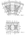
Im folgenden werden zwei Ausführungsbeispiele der Erfindung anhand der Zeichnung erläutert. Es zeigen:
- Fig. 1 + 2 je einen Ausschnitt aus einem horizontalen Teilschnitt durch eine Bremse in Aufsicht.
- Fig. 1 + 2 each a section of a horizontal partial section through a brake in supervision.
Die in den Figuren dargestellten Ausschnitte aus einer Bremse beziehen sich auf solche Bremsen, wie sie eingehend in den beiden in der Einleitung erwähnten Patentanmeldungen beschrieben sind. Der grundsätzliche Aufbau wird deshalb als bekannt vorausgesetzt. Deshalb beschränkt sich die anschliessende Erläuterung auf die erfindungsgemässen Konstruktionsteile.The sections of a brake shown in the figures relate to brakes such as are described in detail in the two patent applications mentioned in the introduction. The basic structure is therefore assumed to be known. The subsequent explanation is therefore limited to the construction parts according to the invention.
In Fig. 1 enthält die ringförmig angeordnete Bremse Polstücke 1, angeordnet zwischen zwei Dauermagneten 2, die ihrerseits je an Rückschlussteile 4 anliegen. In die segmentförmigen Aussparungen der Polstücke 1 greifen Dauermagnete 3, bzw. die an diesen befestigten Polschuhe 5 ein. Wie an sich bekannt, sind die Dauermagnete verdrehbar angeordnet und quer zur Drehachse, die senkrecht zur Bremsfläche stehen, magnetisiert. Im dargestellten, eingeschalteten Zustand weisen alle um das wirksame Poleisen, bestehend aus je einem Polstück 1 und den beiden angrenzenden Polschuhen 5, angeordneten feststehenden und drehbaren Dauermagnete 2 und 3 die gleiche Polarität auf. Die Polarität in den Polstücken 1 und den Polschuhen 5 wird bestimmt von der Polarität derjenigen Dauermagnete, an welche die Flächen 6 der Polstücke 1 bzw. die Flächen 7 der Polschuhe 5 angrenzen.In Fig. 1, the ring-shaped brake contains pole pieces 1, arranged between two
Wie aus der Zeichnung ersichtlich, weisen daher das wirksame Poleisen und auch die daran angrenzenden Dauermagnete gleiche Pole auf.As can be seen from the drawing, the effective pole iron and also the permanent magnets adjoining it have the same poles.
Um zu verhindern, dass an den Ecken des wirksamen Poleisens Streuflüsse daraus in den Luftraum austreten, weisen die Polstücke 1 und die Polschuhe 5 an ihren segmentförmigen Enden Absätze 8 und 9 auf. Damit wird erreicht, dass die angrenzenden Dauermagnete 2 und 3 über die Flächen 6 und 7 der Polstücke 1 und Polschuhe 5 vorstehen. Dies bewirkt die Zurückdrängung des aus dem Weicheisen austretenden Streuflusses, bzw. Streuflussverluste an diesen Stellen werden vermieden.In order to prevent stray fluxes from escaping into the air space at the corners of the effective pole iron, the pole pieces 1 and the
In Fig. 2 enthält die im Prinzip gleich aufgebaute gradlinige Bremse Polstücke 11, angeordnet zwischen je zwei feststehenden Dauermagneten 12, die wiederum an Rückschlussteile 14 angrenzen. Auch hier weisen verdrehbare Dauermagnete 13 je einen segmentförmigen Polschuh 15 an den beiden Polflächen auf. Wiederum greifen die Polschuhe 15 in gegenüberliegende segmentförmige Ausparungen der Polstücke 11 ein. Die Flächen 16 der Polstücke 11, bzw. die Grenzflächen zwischen den Polstücken 11 und den Dauermagneten 12 sind nun im Querschnitt innerhalb der segmentförmigen Linie angeordnet, sodass Dauermagnetmaterial den Endbereich des Luftspaltes bildet. Entsprechend sind auch Flächen 17, bzw. die Grenzflächen zwischen den verdrehbaren Dauermagneten 13 und den Polschuhen 15 angeordnet. Dadurch wird auch hier das Austreten von Streufluss aus dem Poleisen vermieden.In FIG. 2, the straight-line brake, which is constructed in principle in the same way, contains
Claims (2)
Priority Applications (1)
| Application Number | Priority Date | Filing Date | Title |
|---|---|---|---|
| AT81201369T ATE9633T1 (en) | 1981-02-10 | 1981-12-15 | SWITCHABLE, PERMANENT MAGNETIC BRAKE WITH ALTERNATING POLARITY POLES WHICH ARE FIXED AND ROTARY PERMANENT MAGNETS ADJOIN. |
Applications Claiming Priority (2)
| Application Number | Priority Date | Filing Date | Title |
|---|---|---|---|
| CH876/81 | 1981-02-10 | ||
| CH87681 | 1981-02-10 |
Publications (3)
| Publication Number | Publication Date |
|---|---|
| EP0057778A2 true EP0057778A2 (en) | 1982-08-18 |
| EP0057778A3 EP0057778A3 (en) | 1982-08-25 |
| EP0057778B1 EP0057778B1 (en) | 1984-09-26 |
Family
ID=4197228
Family Applications (1)
| Application Number | Title | Priority Date | Filing Date |
|---|---|---|---|
| EP81201369A Expired EP0057778B1 (en) | 1981-02-10 | 1981-12-15 | Switchable permanent magnetic brake, having pole-pieces with changeable polarity, adjacent to fixed and rotatable permanent magnets |
Country Status (8)
| Country | Link |
|---|---|
| EP (1) | EP0057778B1 (en) |
| AT (1) | ATE9633T1 (en) |
| CA (1) | CA1163663A (en) |
| DE (1) | DE3166371D1 (en) |
| FI (1) | FI69687C (en) |
| NO (1) | NO814381L (en) |
| PL (1) | PL132736B1 (en) |
| YU (1) | YU282281A (en) |
Cited By (2)
| Publication number | Priority date | Publication date | Assignee | Title |
|---|---|---|---|---|
| DE29506374U1 (en) * | 1995-04-13 | 1996-10-02 | FUNEX AG, Wollerau | Amusement device |
| US7057321B2 (en) * | 2002-05-28 | 2006-06-06 | Isuzu Motors Limited | Eddy current deceleration device |
Families Citing this family (1)
| Publication number | Priority date | Publication date | Assignee | Title |
|---|---|---|---|---|
| DE102009052447A1 (en) * | 2009-11-09 | 2011-05-12 | Flück, Anton | Device for braking and clutching wheel of motor vehicle, has fixed-bar and fixed-ball magnets, where distance between surface of specific magnets and surface of rotating ball and/or bar magnets is smaller than specific dimension |
Family Cites Families (3)
| Publication number | Priority date | Publication date | Assignee | Title |
|---|---|---|---|---|
| FR2295619A1 (en) * | 1974-12-16 | 1976-07-16 | Siemens Ag | DRIVE DEVICE WITH PERMANENT MAGNET EXCITATION AND INDUCED WITH COLLECTOR FOR DC CURRENT |
| DE2638133C2 (en) * | 1976-08-25 | 1986-05-22 | Baermann, Horst, 5064 Rösrath | Infinitely variable, wear-free permanent magnetic eddy current and / or hysteresis brake, preferably for rail vehicles |
| DE2931539A1 (en) * | 1979-08-03 | 1981-02-19 | Max Baermann | Permanent magnet based switched brake - creates eighteen kilo-gauss field using rotating ferrite magnets |
-
1981
- 1981-12-03 YU YU02822/81A patent/YU282281A/en unknown
- 1981-12-15 AT AT81201369T patent/ATE9633T1/en not_active IP Right Cessation
- 1981-12-15 EP EP81201369A patent/EP0057778B1/en not_active Expired
- 1981-12-15 DE DE8181201369T patent/DE3166371D1/en not_active Expired
- 1981-12-21 NO NO814381A patent/NO814381L/en unknown
-
1982
- 1982-01-25 FI FI820221A patent/FI69687C/en not_active IP Right Cessation
- 1982-01-27 CA CA000395025A patent/CA1163663A/en not_active Expired
- 1982-02-08 PL PL1982234991A patent/PL132736B1/en unknown
Cited By (2)
| Publication number | Priority date | Publication date | Assignee | Title |
|---|---|---|---|---|
| DE29506374U1 (en) * | 1995-04-13 | 1996-10-02 | FUNEX AG, Wollerau | Amusement device |
| US7057321B2 (en) * | 2002-05-28 | 2006-06-06 | Isuzu Motors Limited | Eddy current deceleration device |
Also Published As
| Publication number | Publication date |
|---|---|
| NO814381L (en) | 1982-08-11 |
| PL234991A1 (en) | 1982-09-13 |
| EP0057778B1 (en) | 1984-09-26 |
| PL132736B1 (en) | 1985-04-30 |
| CA1163663A (en) | 1984-03-13 |
| FI820221L (en) | 1982-08-11 |
| EP0057778A3 (en) | 1982-08-25 |
| ATE9633T1 (en) | 1984-10-15 |
| FI69687B (en) | 1985-11-29 |
| DE3166371D1 (en) | 1984-10-31 |
| FI69687C (en) | 1986-03-10 |
| YU282281A (en) | 1984-02-29 |
Similar Documents
| Publication | Publication Date | Title |
|---|---|---|
| EP0127741B2 (en) | Suspension system for a motor vehicle | |
| DE2504766A1 (en) | Eddy current absorbers | |
| DE2438889A1 (en) | VEHICLE WITH LINEAR SYNCHRONOUS MOTOR | |
| EP0057778B1 (en) | Switchable permanent magnetic brake, having pole-pieces with changeable polarity, adjacent to fixed and rotatable permanent magnets | |
| DD222745A1 (en) | PERMANENT MAGNETIC ROLLER FOR ELECTRICAL MACHINES | |
| DE2607197A1 (en) | MAGNETIC SYSTEM WITH A MAGNETIC CIRCUIT CONTAINING AT LEAST TWO MAGNETS | |
| DE967387C (en) | Stand iron body for electrical machines consisting of two concentric parts | |
| EP0114259B1 (en) | Aimant permanent commutable | |
| DE2931539C2 (en) | ||
| DE4314513C2 (en) | Transversal flux machine with combined permanent magnet excitation | |
| DE19838132B4 (en) | Synchronous linear motor | |
| DE2848388A1 (en) | STEEL IRON CORE TO BE FORMED FROM SHEET METAL LAMPS FOR STATIC OR DYNAMIC ELECTRICAL MACHINES, E.g. TRANSFORMERS | |
| EP0001802A1 (en) | Monostable elctromagnetic rotary armature relay | |
| CH409136A (en) | Magnet arrangement and use of the same | |
| DE1964660A1 (en) | Method and device for the orientation of electrically conductive bodies | |
| EP0224660B1 (en) | Commutable permanent-magnet system, in particular for a vehicle brake | |
| DE1174418B (en) | Permanent magnetic stator | |
| CH670535A5 (en) | ||
| DE2833394A1 (en) | ELECTROMAGNETIC RAIL BRAKE FOR RAIL VEHICLES | |
| DE3822842C2 (en) | ||
| DE8235610U1 (en) | MAGNETIC CENTRAL COUPLING | |
| DE874043C (en) | Magnet system for moving coil instruments | |
| DE666596C (en) | Electromagnetic light control device for sound recording | |
| DE2122556C3 (en) | DC machine | |
| DE1000850B (en) | Electromagnetic rail brake |
Legal Events
| Date | Code | Title | Description |
|---|---|---|---|
| PUAI | Public reference made under article 153(3) epc to a published international application that has entered the european phase |
Free format text: ORIGINAL CODE: 0009012 |
|
| PUAL | Search report despatched |
Free format text: ORIGINAL CODE: 0009013 |
|
| AK | Designated contracting states |
Designated state(s): AT BE CH DE FR GB IT NL SE |
|
| AK | Designated contracting states |
Designated state(s): AT BE CH DE FR GB IT NL SE |
|
| 17P | Request for examination filed |
Effective date: 19820920 |
|
| ITF | It: translation for a ep patent filed | ||
| GRAA | (expected) grant |
Free format text: ORIGINAL CODE: 0009210 |
|
| AK | Designated contracting states |
Designated state(s): AT BE CH DE FR GB IT LI NL SE |
|
| REF | Corresponds to: |
Ref document number: 9633 Country of ref document: AT Date of ref document: 19841015 Kind code of ref document: T |
|
| REF | Corresponds to: |
Ref document number: 3166371 Country of ref document: DE Date of ref document: 19841031 |
|
| ET | Fr: translation filed | ||
| PLBE | No opposition filed within time limit |
Free format text: ORIGINAL CODE: 0009261 |
|
| STAA | Information on the status of an ep patent application or granted ep patent |
Free format text: STATUS: NO OPPOSITION FILED WITHIN TIME LIMIT |
|
| 26N | No opposition filed | ||
| PGFP | Annual fee paid to national office [announced via postgrant information from national office to epo] |
Ref country code: FR Payment date: 19891108 Year of fee payment: 9 Ref country code: AT Payment date: 19891108 Year of fee payment: 9 |
|
| PGFP | Annual fee paid to national office [announced via postgrant information from national office to epo] |
Ref country code: SE Payment date: 19891115 Year of fee payment: 9 |
|
| PGFP | Annual fee paid to national office [announced via postgrant information from national office to epo] |
Ref country code: CH Payment date: 19891123 Year of fee payment: 9 Ref country code: BE Payment date: 19891123 Year of fee payment: 9 |
|
| PGFP | Annual fee paid to national office [announced via postgrant information from national office to epo] |
Ref country code: GB Payment date: 19891130 Year of fee payment: 9 Ref country code: DE Payment date: 19891130 Year of fee payment: 9 |
|
| ITTA | It: last paid annual fee | ||
| PGFP | Annual fee paid to national office [announced via postgrant information from national office to epo] |
Ref country code: NL Payment date: 19891231 Year of fee payment: 9 |
|
| PG25 | Lapsed in a contracting state [announced via postgrant information from national office to epo] |
Ref country code: GB Effective date: 19901215 Ref country code: AT Effective date: 19901215 |
|
| PG25 | Lapsed in a contracting state [announced via postgrant information from national office to epo] |
Ref country code: SE Effective date: 19901216 |
|
| PG25 | Lapsed in a contracting state [announced via postgrant information from national office to epo] |
Ref country code: LI Effective date: 19901231 Ref country code: CH Effective date: 19901231 Ref country code: BE Effective date: 19901231 |
|
| BERE | Be: lapsed |
Owner name: WERKZEUGMASCHINENFABRIK OERLIKON-BUHRLE A.G. Effective date: 19901231 |
|
| PG25 | Lapsed in a contracting state [announced via postgrant information from national office to epo] |
Ref country code: NL Effective date: 19910701 |
|
| GBPC | Gb: european patent ceased through non-payment of renewal fee | ||
| NLV4 | Nl: lapsed or anulled due to non-payment of the annual fee | ||
| PG25 | Lapsed in a contracting state [announced via postgrant information from national office to epo] |
Ref country code: FR Effective date: 19910830 |
|
| REG | Reference to a national code |
Ref country code: CH Ref legal event code: PL |
|
| PG25 | Lapsed in a contracting state [announced via postgrant information from national office to epo] |
Ref country code: DE Effective date: 19910903 |
|
| REG | Reference to a national code |
Ref country code: FR Ref legal event code: ST |
|
| EUG | Se: european patent has lapsed |
Ref document number: 81201369.6 Effective date: 19910910 |