EP0057832A2 - Funkentstöranordnung und Verfahren zur Herstellung - Google Patents
Funkentstöranordnung und Verfahren zur Herstellung Download PDFInfo
- Publication number
- EP0057832A2 EP0057832A2 EP82100380A EP82100380A EP0057832A2 EP 0057832 A2 EP0057832 A2 EP 0057832A2 EP 82100380 A EP82100380 A EP 82100380A EP 82100380 A EP82100380 A EP 82100380A EP 0057832 A2 EP0057832 A2 EP 0057832A2
- Authority
- EP
- European Patent Office
- Prior art keywords
- interference suppression
- radio interference
- container
- powder
- choke
- Prior art date
- Legal status (The legal status is an assumption and is not a legal conclusion. Google has not performed a legal analysis and makes no representation as to the accuracy of the status listed.)
- Granted
Links
Images
Classifications
-
- H—ELECTRICITY
- H04—ELECTRIC COMMUNICATION TECHNIQUE
- H04B—TRANSMISSION
- H04B15/00—Suppression or limitation of noise or interference
-
- H—ELECTRICITY
- H01—ELECTRIC ELEMENTS
- H01F—MAGNETS; INDUCTANCES; TRANSFORMERS; SELECTION OF MATERIALS FOR THEIR MAGNETIC PROPERTIES
- H01F17/00—Fixed inductances of the signal type
- H01F17/04—Fixed inductances of the signal type with magnetic core
- H01F17/06—Fixed inductances of the signal type with magnetic core with core substantially closed in itself, e.g. toroid
- H01F17/062—Toroidal core with turns of coil around it
-
- H—ELECTRICITY
- H03—ELECTRONIC CIRCUITRY
- H03H—IMPEDANCE NETWORKS, e.g. RESONANT CIRCUITS; RESONATORS
- H03H1/00—Constructional details of impedance networks whose electrical mode of operation is not specified or applicable to more than one type of network
- H03H1/0007—Constructional details of impedance networks whose electrical mode of operation is not specified or applicable to more than one type of network of radio frequency interference filters
-
- H—ELECTRICITY
- H03—ELECTRONIC CIRCUITRY
- H03H—IMPEDANCE NETWORKS, e.g. RESONANT CIRCUITS; RESONATORS
- H03H7/00—Multiple-port networks comprising only passive electrical elements as network components
- H03H7/42—Networks for transforming balanced signals into unbalanced signals and vice versa, e.g. baluns
- H03H7/425—Balance-balance networks
- H03H7/427—Common-mode filters
Definitions
- the invention relates to a radio interference suppression arrangement, which is arranged in a container encapsulated with insulating material, with a choke consisting of a toroidal core made of soft magnetic material, to which at least two windings through which the mains current flows are applied, magnetically conductive material being arranged in the vicinity of the choke .
- a radio interference suppressor arrangement which contains a current-compensated multiple choke.
- at least two windings are applied to an annular core.
- the operating current flows through these windings in such a way that the magnetic effects of the operating current flowing back and forth cancel each other out.
- This makes it possible to achieve a high level of attenuation for unbalanced interference currents, which is in connection with between the conductors and the earth arranged capacitors can still be improved.
- earth-symmetric interference currents cancel each other out in their magnetic effect like the operating currents, an increase in the leakage inductance of the radio interference suppression choke is provided to damp the earth-symmetrical currents.
- the choke is arranged in a container made of electrically conductive material and, if necessary, magnetically conductive parts are additionally provided below or in the center of the toroid.
- the object of the present invention is to achieve a radio interference suppression arrangement which is easier to manufacture and dimension and which, with the same output, permits a reduced overall volume.
- the solution to this problem is, according to the invention, that in the container there is at least in the vicinity of the throttle powder made of magnetically conductive material, which is embedded in the sealing compound.
- the leakage inductance can be reduced by using the embedding of the choke in powder made of magnetically conductive material by choosing the grain size of the powder or by the mixing ratio between the powder and the insulating casting compound. This requires a significant simplification in the manufacture. Furthermore As a result of the powder completely surrounding the choke, the thermal conductivity is effectively improved on all sides, so that the choke windings have a higher load capacity with the same dimensions. Furthermore, it is achieved with the arrangement according to the invention that the stray flux which is formed is distributed over a large cross section which encompasses the entire envelope surface of the winding. This also permits a higher current compared to the known arrangement, since the saturation induction is only achieved at higher operating currents because of the larger cross section available to the leakage flux.
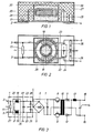
- FIG. 3 shows the circuit diagram of the radio interference suppression arrangement connected to a switching power supply.
- the radio interference suppression arrangement 1 is connected to the terminals 2 and 3 of an AC network and has output terminals 4 and 5 which are connected to a rectifier 6.
- the rectified current passes in a known manner to a chopper consisting of a capacitor 7, thyristors 8 and 9, a transformer 10 with downstream diodes 11 and 12 and a smoothing element consisting of a series choke 13 and a transverse capacitor 14.
- a chopper consisting of a capacitor 7, thyristors 8 and 9
- At the output terminals 15 and 16 of the switching power supply is then a rectified voltage of the desired size.
- the radio interference suppression arrangement 1 consists in particular of a discharge resistor 17, which is connected between the terminals 2 and 3, of the windings 18 and 19 of a current-compensating choke 20 with an annular core 21, on which the windings 18 and 19 are wound so that the compensate for the induction in the toroidal core 21 caused by the operating currents.
- the free ends of the windings 18 and 19 are guided via lines 22 and 23 to the output terminals 4 and 5 of the radio interference suppression arrangement 1.
- the radio interference suppression arrangement is in a potting compound, e.g. Cast resin, potted outer container 27 arranged. In this there can be another container 28, which only receives the throttle 20.
- the rapidly switchable thyristors 8 and 9 generate high-frequency currents and voltages which are to be kept away from the electrical network by the radio interference suppression arrangement.
- high-frequency interference currents coming from the network are to be suppressed by the radio interference suppression arrangement.
- the inductor 20 has a high leakage inductance within the radio interference suppression arrangement, without the inductance with respect to the asymmetrical interference current being reduced.
- the throttle 20 is embedded in iron powder 29 which is enclosed by the wall of the container 28 or the potting compound 30.
- the wound inductor can simply be embedded in a certain amount of iron powder according to the invention.
- the entire radio interference suppression arrangement is then cast with an insulating potting compound.
- the radio interference suppression arrangement is to withstand higher voltages, it is particularly advantageous to mix the potting compound for the inductor in the liquid state with iron powder or powder from other soft magnetic materials and use this mixture to encapsulate the entire radio interference suppression arrangement or only the container 28. In this case there are already insulation distances between the individual particles of the iron powder in the vicinity of the choke, so that the insulation of the windings can possibly also be reduced or even superfluous.
Landscapes
- Engineering & Computer Science (AREA)
- Power Engineering (AREA)
- Microelectronics & Electronic Packaging (AREA)
- Computer Networks & Wireless Communication (AREA)
- Signal Processing (AREA)
- Filters And Equalizers (AREA)
- Coils Or Transformers For Communication (AREA)
- Insulating Of Coils (AREA)
Abstract
Description
- Die Erfindung betrifft eine Funkentstöranordnung, die in einem mit Isoliermaterial vergossenen Behälter angeordnet ist, mit einer Drossel, bestehend aus einem Ringkern aus weichmagnetischem Material, auf den mindestens zwei vom Netzstrom durchflossene Wicklungen aufgebracht sind, wobei in der Nähe der Drossel magnetisch leitendes Material angeordnet ist.
- Beispielsweise aus dem deutschen Gebrauchsmuster Nr. 70 37 848 ist eine Funkentstöranordnung bekannt, die eine stromkompensierte Mehrfachdrossel enthält. Hier werden auf einem ringförmigen Kern mindestens zwei Wicklungen aufgebracht. Diese Wicklungen werden vom Betriebsstrom so durchflossen, daß sich die magnetischen Wirkungen des hin- und rückfließenden Betriebsstromes im Ringkern gegenseitig aufheben. Hierdurch läßt sich für erdunsymmetrische Störströme eine hohe Dämpfung erzielen, die in Verbindung mit zwischen den Leitern und der Erde angeordneten Kondensatoren noch verbessert werden kann. Da erdsymmetrische Störströme sich in ihrer magnetischen Wirkung im Kern wie die Betriebsströme aufheben, wird zur Dämpfung der erdsymmetrischen Ströme eine Erhöhung der Streuinduktivität der Funkentstördrossel vorgesehen. Zur Erhöhung dieser Streuinduktivität wird die Drossel in einem Behälter aus elektrisch leitendem Material angeordnet und es werden gegebenenfalls unterhalb oder im Mittelpunkt des Ringkernes zusätzlich magnetisch leitende Teile vorgesehen.
- Aufgabe der vorliegenden Erfindung ist es demgegenüber, eine Funkentstöranordnung zu erreichen, die einfacher herzustellen und zu dimensionieren ist und bei gleicher Leistung ein verringertes Bauvolumen zuläßt.
- Die Lösung dieser Aufgabe besteht erfindungsgemäß darin, daß sich im Behälter mindestens in der Nähe der Drossel Pulver aus magnetisch leitendem Material befindet, das in die Vergußmasse eingebettet ist.
- Während bei bekannten Funkentstöranordnungen zur Einstellung der Streuinduktivität zwischen die zusätzlich vorgesehenen Teile aus magnetisch leitendem Material und der Drossel ein definierter Abstand eingehalten werden muß, läßt sich die Streuinduktivität bei der Verwendung der Einbettung der Drossel in Pulver aus magnetisch leitendem Material durch Wahl der Korngröße des Pulvers bzw. durch das Mischungsverhältnis zwischen dem Pulver und der isolierenden Vergußmasse festlegen. Dies bedingt eine wesentliche Vereinfachung bei der Herstellung. Außerdem ergibt sich durch das die Drossel vollständig umgebende Pulver eine nach allen Seiten wirksam verbesserte Wärmeleitfähigkeit, so daß eine höhere Belastbarkeit der Drosselwicklungen bei gleichen Abmessungen gegeben ist. Weiterhin wird bei der erfindungsgemäßen Anordnung erreicht, daß der sich bildende Streufluß auf einen großen, die gesamte Hüllfläche der Wicklung umfassenden Querschnitt verteilt wird. Auch hierdurch ist ein höherer Strom gegenüber der bekannten Anordnung zulässig, da die Sättigungsinduktion wegen des größeren, dem Streufluß zur Verfügung stehenden Querschnittes erst bei höheren Betriebsströmen erreicht wird.
- Ein Ausführungsbeispiel ist in den Figuren 1 und 2 in zwei Schnitten dargestellt. Figur 3 zeigt das Schaltbild der an ein Schaltnetzteil angeschlossenen Funkentstöranordnung.
- Die Funkentstöranordnung 1 ist an die Klemmen 2 und 3 eines Wechselstromnetzes angeschlossen und besitzt Ausgangsklemmen 4 und 5, die mit einem Gleichrichter 6 in Verbindung stehen. Der gleichgerichtete Strom gelangt in bekannter Weise an einen Zerhacker, bestehend aus einem Kondensator 7, Thyristoren 8 und 9, einem Transformator 10 mit nachgeschalteten Dioden 11 und 12 und einem Glättungsglied, bestehend aus einer Längsdrossel 13 und einem Querkondensator 14. An den Ausgangsklemmen 15 und 16 des Schaltnetzteiles steht dann eine gleichgerichtete Spannung gewünschter Größe an.
- Die Funkentstöranordnung 1 besteht im einzelnen aus einem Entladewiderstand 17, der zwischen die Klemmen 2 und 3 geschaltet ist, aus den Wicklungen 18 und 19 einer stromkompensierenden Drossel 20 mit einem Ringkern 21, auf den die Wicklungen 18 und 19 so aufgewickelt sind, daß sich die durch die Betriebsströme hervorgerufenen Induktionen im Ringkern 21 kompensieren. Die freien Enden der Wicklungen 18 und 19 sind über Leitungen 22 und 23 an die Ausgangsklemmen 4 und 5 der Funkentstöranordnung 1 geführt. Zwischen den Leitungen 22 und 23 und zwischen diesen Leitungen und der Erde befindet sich je ein Kondensator 24 bis 26. Die Funkentstöranordnung ist in einem mit Vergußmasse, z.B. Gießharz, vergossenen Außenbehälter 27 angeordnet. In diesem kann sich ein weiterer Behälter 28 befinden, der nur die Drossel 20 aufnimmt.
- Durch die schnell ein- und ausschaltbaren Thyristoren 8 und 9 entstehen hochfrequente Ströme und Spannungen, die durch die Funkentstöranordnung vom elektrischen Netz ferngehalten werden sollen. Außerdem sollen durch die Funkentstöranordnung vom Netz herkommende, hochfrequente Störströme unterdrückt werden. Um auch die erdsymmetrischen Ströme gut zu dämpfen, die wie der Betriebsstrom zwischen den Leitungen 22 und 23 fließen, ist es vorteilhaft, wenn die Drossel 20 innerhalb der Funkentstöranordnung eine hohe Streuinduktivität besitzt, ohne daß die Induktivität bezüglich des unsymmetrischen Störstromes vermindert wird. Hierzu wird, wie Fig. 1 und Fig. 2 zeigen, die Drossel 20 in Eisenpulver 29 eingebettet, das von der Wand des Behälters 28 bzw. der Vergußmasse 30 umschlossen ist.
- Zur Herstellung der Drossel mit erhöhter Streuinduktivität kann die bewickelte Drossel erfindungsgemäß einfach in eine bestimmte Menge von Eisenpulver eingebettet werden. Anschließend wird die gesamte Funkentstöranordnung mit isolierender Vergußmasse vergossen.
- Für den Fall, daß die Funkentstöranordnung höhere Spannungen aushalten soll, kann man mit besonderem Vorteil die Vergußmasse für die Drossel in flüssigem Zustand mit Eisenpulver oder Pulver aus anderen weichmagnetischen Materialien mischen und dieses Gemisch zum Vergießen der gesamten Funkentstöranordnung oder nur des Behälters 28 verwenden. In diesem Fall sind auch bereits in der Nähe der Drossel Isolationsabstände zwischen den einzelnen Partikeln des Eisenpulvers vorhanden, so daß eventuell auch die Isolierung der Wicklungen vermindert werden kann, oder gar überflüssig ist.
Claims (5)
Applications Claiming Priority (2)
| Application Number | Priority Date | Filing Date | Title |
|---|---|---|---|
| DE3104270 | 1981-02-07 | ||
| DE19813104270 DE3104270A1 (de) | 1981-02-07 | 1981-02-07 | Funkentstoeranordnung und verfahren zur herstellung |
Publications (3)
| Publication Number | Publication Date |
|---|---|
| EP0057832A2 true EP0057832A2 (de) | 1982-08-18 |
| EP0057832A3 EP0057832A3 (en) | 1982-09-01 |
| EP0057832B1 EP0057832B1 (de) | 1985-01-02 |
Family
ID=6124257
Family Applications (1)
| Application Number | Title | Priority Date | Filing Date |
|---|---|---|---|
| EP82100380A Expired EP0057832B1 (de) | 1981-02-07 | 1982-01-21 | Funkentstöranordnung und Verfahren zur Herstellung |
Country Status (3)
| Country | Link |
|---|---|
| US (1) | US4543554A (de) |
| EP (1) | EP0057832B1 (de) |
| DE (2) | DE3104270A1 (de) |
Cited By (5)
| Publication number | Priority date | Publication date | Assignee | Title |
|---|---|---|---|---|
| DE4137685A1 (de) * | 1990-11-16 | 1992-05-21 | Mitsubishi Electric Corp | Drossel aus einer vielzahl von elementen |
| WO1998012718A1 (de) * | 1996-09-16 | 1998-03-26 | Vacuumschmelze Gmbh | Stromkompensierte funkentstördrossel mit erhöhter streuinduktivität |
| EP0848392A4 (de) * | 1995-09-01 | 1999-08-18 | Mitsui Chemicals Inc | Magnetkern in einem gehäuse |
| DE102004001255B4 (de) * | 2004-01-07 | 2006-04-27 | Vacuumschmelze Gmbh & Co. Kg | Entstörelement und Verfahren zu seiner Herstellung |
| WO2013061220A1 (en) * | 2011-10-25 | 2013-05-02 | Brusa Elektronik Ag | Inductive component and use |
Families Citing this family (40)
| Publication number | Priority date | Publication date | Assignee | Title |
|---|---|---|---|---|
| DE3211112C2 (de) * | 1982-03-26 | 1984-08-30 | Standard Elektrik Lorenz Ag, 7000 Stuttgart | An ein öffentliches Wechselspannungsversorgungsnetz anschließbares Gerät der Unterhaltungselektronik mit einem Entstörungsglied |
| DE3526047A1 (de) * | 1985-07-20 | 1987-01-22 | Vacuumschmelze Gmbh | Stromkompensierte funkentstoerdrossel |
| JPS6282709A (ja) * | 1985-10-07 | 1987-04-16 | Murata Mfg Co Ltd | ラインフイルタ |
| DE3735989A1 (de) * | 1987-10-23 | 1989-05-03 | Beme Electronic Gmbh | Schaltnetzgeraet |
| US5163181A (en) * | 1988-10-21 | 1992-11-10 | Harris Corporation | Multiple rf signal amplification method and apparatus |
| US5091707A (en) * | 1990-08-13 | 1992-02-25 | Wollmerschauser Steven M | Coaxial cable shield filter |
| US5222149A (en) * | 1991-11-15 | 1993-06-22 | Palmer Donald E | Damping terminator for high fidelity audio signals |
| US5594397A (en) * | 1994-09-02 | 1997-01-14 | Tdk Corporation | Electronic filtering part using a material with microwave absorbing properties |
| DE19515494A1 (de) * | 1995-04-27 | 1996-10-31 | Vacuumschmelze Gmbh | Stromkompensierte Funkentstördrossel mit erhöhter Streuinduktivität |
| KR0168961B1 (ko) * | 1995-06-07 | 1999-03-20 | 이형도 | 포면실장 부품용 라인필터 |
| US7034645B2 (en) * | 1999-03-16 | 2006-04-25 | Vishay Dale Electronics, Inc. | Inductor coil and method for making same |
| US6198375B1 (en) * | 1999-03-16 | 2001-03-06 | Vishay Dale Electronics, Inc. | Inductor coil structure |
| US7263761B1 (en) * | 1995-07-18 | 2007-09-04 | Vishay Dale Electronics, Inc. | Method for making a high current low profile inductor |
| CA2180992C (en) * | 1995-07-18 | 1999-05-18 | Timothy M. Shafer | High current, low profile inductor and method for making same |
| US7921546B2 (en) * | 1995-07-18 | 2011-04-12 | Vishay Dale Electronics, Inc. | Method for making a high current low profile inductor |
| US5739732A (en) * | 1996-01-23 | 1998-04-14 | Kit; Page Huie Man | AC noise spike suppression circuit with parallel back-to-back fast diodes |
| JP3295355B2 (ja) * | 1997-09-19 | 2002-06-24 | 東光株式会社 | 電子部品 |
| US6710673B1 (en) | 1998-06-26 | 2004-03-23 | Thomas Jokerst | Return path noise reducer |
| JP4579448B2 (ja) * | 2000-06-12 | 2010-11-10 | マスプロ電工株式会社 | 雑音除去装置 |
| US20030078005A1 (en) * | 2001-10-18 | 2003-04-24 | Airnet Ltd. | Apparatus and methods for noise suppression in communications systems |
| US9013259B2 (en) | 2010-05-24 | 2015-04-21 | Volterra Semiconductor Corporation | Powder core material coupled inductors and associated methods |
| US8416043B2 (en) | 2010-05-24 | 2013-04-09 | Volterra Semiconductor Corporation | Powder core material coupled inductors and associated methods |
| US8952776B2 (en) | 2002-12-13 | 2015-02-10 | Volterra Semiconductor Corporation | Powder core material coupled inductors and associated methods |
| US20080036566A1 (en) | 2006-08-09 | 2008-02-14 | Andrzej Klesyk | Electronic Component And Methods Relating To Same |
| JP5175843B2 (ja) * | 2007-04-17 | 2013-04-03 | 株式会社東芝 | インダクタンス素子とその製造方法、およびそれを用いたスイッチング電源 |
| US20090128276A1 (en) * | 2007-11-19 | 2009-05-21 | John Horowy | Light weight reworkable inductor |
| WO2009114872A1 (en) | 2008-03-14 | 2009-09-17 | Volterra Semiconductor Corporation | Magnetic components with m-phase coupling, and related inductor structures |
| CN101930821B (zh) * | 2009-06-25 | 2012-11-14 | 浙江三花股份有限公司 | 一种电磁线圈装置 |
| US8638187B2 (en) | 2009-07-22 | 2014-01-28 | Volterra Semiconductor Corporation | Low profile inductors for high density circuit boards |
| US8299882B2 (en) * | 2009-07-22 | 2012-10-30 | Volterra Semiconductor Corporation | Low profile inductors for high density circuit boards |
| US7994888B2 (en) | 2009-12-21 | 2011-08-09 | Volterra Semiconductor Corporation | Multi-turn inductors |
| US8174348B2 (en) | 2009-12-21 | 2012-05-08 | Volterra Semiconductor Corporation | Two-phase coupled inductors which promote improved printed circuit board layout |
| US8674802B2 (en) | 2009-12-21 | 2014-03-18 | Volterra Semiconductor Corporation | Multi-turn inductors |
| US8203410B2 (en) * | 2010-03-03 | 2012-06-19 | Honeywell International Inc. | Inductor assembly |
| WO2012108254A1 (ja) * | 2011-02-09 | 2012-08-16 | 株式会社村田製作所 | 高周波モジュール |
| US9373438B1 (en) | 2011-11-22 | 2016-06-21 | Volterra Semiconductor LLC | Coupled inductor arrays and associated methods |
| US10128035B2 (en) | 2011-11-22 | 2018-11-13 | Volterra Semiconductor LLC | Coupled inductor arrays and associated methods |
| KR102032791B1 (ko) * | 2013-06-03 | 2019-10-16 | 삼성전자주식회사 | 노이즈 필터 및 이를 포함하는 전자장치 |
| DE102015200666B4 (de) * | 2015-01-16 | 2024-10-10 | Vacuumschmelze Gmbh & Co. Kg | Magnetkern, Verfahren zur Herstellung eines solchen Magnetkerns und Verfahren zum Herstellen einer elektrischen oder elektronischen Baugruppe mit einem solchen Magnetkern |
| DE102022211604A1 (de) * | 2022-11-03 | 2024-05-08 | Zf Friedrichshafen Ag | Speicherdrossel für einen Gleichspannungswandler mit einer magnetischen Vergussmasse |
Family Cites Families (9)
| Publication number | Priority date | Publication date | Assignee | Title |
|---|---|---|---|---|
| FR1315581A (fr) * | 1961-02-24 | 1963-01-18 | Siemens Ag | Procédé pour fabriquer des corps frittés isolants tenant le vide |
| US3230488A (en) * | 1961-11-01 | 1966-01-18 | Ericsson Telefon Ab L M | Transformer with a carefully adjusted primary inductance |
| DE1439460A1 (de) * | 1964-10-19 | 1968-12-12 | Siemens Ag | Elektrisches Bauelement,insbesondere Halbleiterbauelement,mit einer aus isolierendemStoff bestehenden Huelle |
| AT301714B (de) * | 1968-10-15 | 1972-09-11 | Vacuumschmelze Gmbh | Ringkerndrossel, die aus zwei Magnetkernen zusammengesetzt ist |
| AT293566B (de) * | 1968-11-02 | 1971-10-11 | Vacuumschmelze Gmbh | Geräuscharme Funkentstördrossel |
| US3538472A (en) * | 1969-04-09 | 1970-11-03 | Westinghouse Electric Corp | Magnetic shielding for electrical transformer |
| DE2050312A1 (de) * | 1970-10-13 | 1972-04-20 | Siemens Ag | Mehrfachdrossel mit Dämpfung von symmetrischen Störströmen |
| DE7037848U (de) * | 1970-10-13 | 1971-07-29 | Siemens Ag | Mehrfachdrossel mit Dampfung von symmetrischen Storstromen |
| FR2218634A1 (en) * | 1973-02-16 | 1974-09-13 | Eurofarad | Electrical condensers of low thermal sensitivity - clad in insulation of relatively low thermal expansion |
-
1981
- 1981-02-07 DE DE19813104270 patent/DE3104270A1/de not_active Withdrawn
-
1982
- 1982-01-21 DE DE8282100380T patent/DE3261718D1/de not_active Expired
- 1982-01-21 EP EP82100380A patent/EP0057832B1/de not_active Expired
- 1982-01-26 US US06/342,850 patent/US4543554A/en not_active Expired - Fee Related
Cited By (7)
| Publication number | Priority date | Publication date | Assignee | Title |
|---|---|---|---|---|
| DE4137685A1 (de) * | 1990-11-16 | 1992-05-21 | Mitsubishi Electric Corp | Drossel aus einer vielzahl von elementen |
| EP0848392A4 (de) * | 1995-09-01 | 1999-08-18 | Mitsui Chemicals Inc | Magnetkern in einem gehäuse |
| WO1998012718A1 (de) * | 1996-09-16 | 1998-03-26 | Vacuumschmelze Gmbh | Stromkompensierte funkentstördrossel mit erhöhter streuinduktivität |
| DE102004001255B4 (de) * | 2004-01-07 | 2006-04-27 | Vacuumschmelze Gmbh & Co. Kg | Entstörelement und Verfahren zu seiner Herstellung |
| WO2013061220A1 (en) * | 2011-10-25 | 2013-05-02 | Brusa Elektronik Ag | Inductive component and use |
| CN104025213A (zh) * | 2011-10-25 | 2014-09-03 | 布鲁萨电子公司 | 电感性组件和使用 |
| EP2771891B1 (de) | 2011-10-25 | 2018-09-05 | BRUSA Elektronik AG | Induktives bauteil sowie verwendung |
Also Published As
| Publication number | Publication date |
|---|---|
| EP0057832B1 (de) | 1985-01-02 |
| DE3261718D1 (en) | 1985-02-14 |
| US4543554A (en) | 1985-09-24 |
| DE3104270A1 (de) | 1982-09-02 |
| EP0057832A3 (en) | 1982-09-01 |
Similar Documents
| Publication | Publication Date | Title |
|---|---|---|
| EP0057832B1 (de) | Funkentstöranordnung und Verfahren zur Herstellung | |
| DE2050312A1 (de) | Mehrfachdrossel mit Dämpfung von symmetrischen Störströmen | |
| DE2411246A1 (de) | Drehstromnetztransformator | |
| DE2245208A1 (de) | Funk-entstoerdrossel | |
| DE3590224T1 (de) | Leistungstransformator für integrierte Höchstgeschwindigkeitsschaltungen | |
| DE3833916A1 (de) | Wechselstromnetzfilter | |
| DE102017222664A1 (de) | Gleichtakt-Gegentakt-Drossel für ein elektrisch betreibbares Kraftfahrzeug | |
| EP0275499B1 (de) | Stromkompensierte Drossel zur Funk-Entstörung | |
| EP0066804A2 (de) | Zeilentransformator für Fernsehgeräte | |
| DE19637733C1 (de) | Stromkompensierte Funkentstördrossel mit erhöhter Streuinduktivität | |
| DE822571C (de) | Stromwandler | |
| WO1999016091A1 (de) | Geometrie für planare induktivitäten | |
| CH639225A5 (de) | Halbleiterschaltkreis mit mindestens einer in serie geschalteten drosselspule, insbesondere fuer elektrische umformer. | |
| DE4325056C1 (de) | Planar-Transduktor | |
| DE2609707A1 (de) | Transformator | |
| DE4340020A1 (de) | Induktiver elektrischer Wandler | |
| DE878983C (de) | Isoliertransformator fuer hohe Spannungen | |
| DE417887C (de) | Stromwandler mit einem die Primaerwicklung tragenden stabfoermigen Eisenkern, der in einem aussen die Sekundaerwicklung tragenden Isolierrohr eingeschlossen ist, insbesondere fuer den Anschluss von Messgeraeten | |
| DE3739554A1 (de) | Transformator | |
| DE767485C (de) | Drosselspulenanordnung, insbesondere zur Spannungsregelung von Wechselstromfernleitungen | |
| DE615699C (de) | Spule fuer Fernmeldezwecke, insbesondere fuer die Belastung von Fernmeldeleitungen | |
| DE1638521C3 (de) | Kombinierter Strom- und Spannungswandler | |
| AT320067B (de) | Regeltransformator bzw. -stabilisator | |
| DE424958C (de) | Elektromagnetische Induktanzspule | |
| DE338567C (de) | Wicklungsanordnung bei Nullpunkt-Erdschlussschaltungen von Hochspannungsnetzen |
Legal Events
| Date | Code | Title | Description |
|---|---|---|---|
| PUAI | Public reference made under article 153(3) epc to a published international application that has entered the european phase |
Free format text: ORIGINAL CODE: 0009012 |
|
| PUAL | Search report despatched |
Free format text: ORIGINAL CODE: 0009013 |
|
| AK | Designated contracting states |
Designated state(s): CH DE FR GB IT |
|
| AK | Designated contracting states |
Designated state(s): CH DE FR GB IT |
|
| 17P | Request for examination filed |
Effective date: 19830117 |
|
| ITF | It: translation for a ep patent filed | ||
| GRAA | (expected) grant |
Free format text: ORIGINAL CODE: 0009210 |
|
| AK | Designated contracting states |
Designated state(s): CH DE FR GB IT LI |
|
| REF | Corresponds to: |
Ref document number: 3261718 Country of ref document: DE Date of ref document: 19850214 |
|
| ET | Fr: translation filed | ||
| PLBE | No opposition filed within time limit |
Free format text: ORIGINAL CODE: 0009261 |
|
| STAA | Information on the status of an ep patent application or granted ep patent |
Free format text: STATUS: NO OPPOSITION FILED WITHIN TIME LIMIT |
|
| 26N | No opposition filed | ||
| PGFP | Annual fee paid to national office [announced via postgrant information from national office to epo] |
Ref country code: GB Payment date: 19901212 Year of fee payment: 10 |
|
| PGFP | Annual fee paid to national office [announced via postgrant information from national office to epo] |
Ref country code: FR Payment date: 19910123 Year of fee payment: 10 |
|
| ITTA | It: last paid annual fee | ||
| PGFP | Annual fee paid to national office [announced via postgrant information from national office to epo] |
Ref country code: DE Payment date: 19910308 Year of fee payment: 10 |
|
| PGFP | Annual fee paid to national office [announced via postgrant information from national office to epo] |
Ref country code: CH Payment date: 19910315 Year of fee payment: 10 |
|
| PG25 | Lapsed in a contracting state [announced via postgrant information from national office to epo] |
Ref country code: GB Effective date: 19920121 |
|
| PG25 | Lapsed in a contracting state [announced via postgrant information from national office to epo] |
Ref country code: LI Effective date: 19920131 Ref country code: CH Effective date: 19920131 |
|
| REG | Reference to a national code |
Ref country code: GB Ref legal event code: PCNP |
|
| PG25 | Lapsed in a contracting state [announced via postgrant information from national office to epo] |
Ref country code: FR Effective date: 19920930 |
|
| REG | Reference to a national code |
Ref country code: CH Ref legal event code: PL |
|
| PG25 | Lapsed in a contracting state [announced via postgrant information from national office to epo] |
Ref country code: DE Effective date: 19921001 |
|
| REG | Reference to a national code |
Ref country code: FR Ref legal event code: ST |