EP0057956A2 - Tête à écrire pour une imprimante à jet d'encre - Google Patents
Tête à écrire pour une imprimante à jet d'encre Download PDFInfo
- Publication number
- EP0057956A2 EP0057956A2 EP82200100A EP82200100A EP0057956A2 EP 0057956 A2 EP0057956 A2 EP 0057956A2 EP 82200100 A EP82200100 A EP 82200100A EP 82200100 A EP82200100 A EP 82200100A EP 0057956 A2 EP0057956 A2 EP 0057956A2
- Authority
- EP
- European Patent Office
- Prior art keywords
- nozzle
- channel
- drive elements
- channels
- nozzle channels
- Prior art date
- Legal status (The legal status is an assumption and is not a legal conclusion. Google has not performed a legal analysis and makes no representation as to the accuracy of the status listed.)
- Granted
Links
- 239000007788 liquid Substances 0.000 claims abstract description 29
- 238000009826 distribution Methods 0.000 claims abstract description 15
- 230000005499 meniscus Effects 0.000 claims abstract description 5
- 238000013016 damping Methods 0.000 claims description 10
- 238000004519 manufacturing process Methods 0.000 claims description 9
- 238000000034 method Methods 0.000 claims description 7
- 230000008569 process Effects 0.000 claims description 3
- 238000009966 trimming Methods 0.000 claims description 3
- 238000013022 venting Methods 0.000 claims description 2
- 238000005266 casting Methods 0.000 description 7
- 239000011159 matrix material Substances 0.000 description 4
- 239000011347 resin Substances 0.000 description 4
- 229920005989 resin Polymers 0.000 description 4
- 239000011521 glass Substances 0.000 description 3
- 230000008901 benefit Effects 0.000 description 2
- 230000008859 change Effects 0.000 description 2
- 239000000463 material Substances 0.000 description 2
- 230000007704 transition Effects 0.000 description 2
- 239000000969 carrier Substances 0.000 description 1
- 238000005520 cutting process Methods 0.000 description 1
- 230000005672 electromagnetic field Effects 0.000 description 1
- 238000005530 etching Methods 0.000 description 1
- 239000004744 fabric Substances 0.000 description 1
- 230000007246 mechanism Effects 0.000 description 1
- 230000004048 modification Effects 0.000 description 1
- 238000012986 modification Methods 0.000 description 1
- 239000013642 negative control Substances 0.000 description 1
- 239000013641 positive control Substances 0.000 description 1
- 239000003566 sealing material Substances 0.000 description 1
- 229920002379 silicone rubber Polymers 0.000 description 1
- 239000004945 silicone rubber Substances 0.000 description 1
- 238000005507 spraying Methods 0.000 description 1
- 239000000126 substance Substances 0.000 description 1
Images
Classifications
-
- B—PERFORMING OPERATIONS; TRANSPORTING
- B41—PRINTING; LINING MACHINES; TYPEWRITERS; STAMPS
- B41J—TYPEWRITERS; SELECTIVE PRINTING MECHANISMS, i.e. MECHANISMS PRINTING OTHERWISE THAN FROM A FORME; CORRECTION OF TYPOGRAPHICAL ERRORS
- B41J2/00—Typewriters or selective printing mechanisms characterised by the printing or marking process for which they are designed
- B41J2/005—Typewriters or selective printing mechanisms characterised by the printing or marking process for which they are designed characterised by bringing liquid or particles selectively into contact with a printing material
- B41J2/01—Ink jet
- B41J2/135—Nozzles
- B41J2/14—Structure thereof only for on-demand ink jet heads
- B41J2/14201—Structure of print heads with piezoelectric elements
- B41J2/1429—Structure of print heads with piezoelectric elements of tubular type
Definitions
- the invention relates to a write head for inkjet printers with a plurality of tubular nozzle channels, each of which is assigned a drive element for the drop-shaped ejection of ink droplets as required and to which the ink is supplied via a common distributor channel and separately assigned attenuators, the nozzle channels with their drive elements and the common distributor channel in separate blocks of preferably plastic are arranged, which are interconnected.
- Such a write head is known, for example, from DE-OS 26 59 398, which contains a plurality of channels and drive elements, in order to represent characters in the form of an ink drop matrix, in particular as an ink-jet writing mechanism.
- These print heads essentially consist of two plastic blocks.
- the tubular nozzle channels with their drive elements are cast into one plastic block.
- the channels are cast in a fan-shaped and straight line and open at their front ends in a separate nozzle plate, in which the nozzles are then aligned parallel to one another.
- each channel is shaped so that it has a parallel cross section in the area of the cylindrical drive elements, which is relatively large.
- the geometric arrangement of the nozzles in the nozzle plate is designed so that the spacing of the nozzles from one another corresponds to the conditions resulting from the grid-like structure of the characters to be printed speaks. For example, with a character height of 3.2 mm, the nozzle center distance for six nozzles is 0.53 mm. In order to meet this condition, the nozzle channels in the area between the drive elements and the nozzles must be conical. This means more work and materials.
- the second plastic block contains a trough-shaped recess into which the liquid is introduced. Both plastic blocks are firmly connected to each other at their edges.
- a further plate is provided between the plastic blocks, in which damping ducts (throttles) are arranged, the pipe cross-section of which is smaller than the cross-section of the nozzle ducts and which are parallel to one another.
- the known system is difficult to fill with liquid without trapping gas bubbles in the transition zones.
- Any misalignment between the pressure channel and the nozzle element promotes the inclusion of glass bubbles, not only when the liquid is filled for the first time, but also during operation because, for example, the liquid can flow back into the interior of the system due to vibrations and then air bubbles are trapped at the critical points when it is rushed forward .
- Any offset between pressure channel and nozzle element also in any case obstructs the pressure line and causes pressure losses.
- a writing element for inkjet printers is known from US Pat. No. 3,832,579, the tubular nozzle channel of which is made of glass and runs in a straight line from the area of the drive element to the outlet nozzle with the same, relatively large cross-section.
- Nozzle channel and nozzle consist of one Piece.
- a hose is attached to the end of the nozzle channel facing away from the nozzle, via which the ink is supplied from an ink reservoir.
- This hose has a smaller cross section than the nozzle channel, so that it acts as an attenuator.
- the electromechanical, preferably piezoelectric drive element is arranged in tubular form around the nozzle channel and, when electrically controlled, exerts a pressure on the liquid in the nozzle channel. This pressure is not only directed towards the outlet nozzle, but also towards the rear in the opposite direction. Since the ejection of the liquid is only desired towards the front of the nozzle, the damping element is provided on the rear nozzle channel.
- the object of the invention is to improve on the one hand the filling of the print head with ink liquid, to make the drop emission safer and to provide a simple manufacturing method for such a write head with several channels, and on the other hand to ensure the smallest possible center distances of the outlet nozzles even when the Nozzle channels all over their Length of constant cross-section.
- the nozzle channels are integrally formed both with their outlet nozzles and with their damping members, that the nozzle channels open vertically into the distribution channel and that the nozzle channels are deflected in the area between the drive elements and the outlet nozzles in such a way that they are deflected into the the remaining areas run parallel to one another, the distance in the area of the outlet nozzles being determined by the required distance of the mosaic-like ink droplets on the recording medium and in the rear area by the dimensions of the drive elements.
- the drive elements themselves are expediently kept freely accessible so that they can be adjusted subsequently and all the writing nozzles have the same drop emission.
- the distribution channel is tubular and has a larger cross section than the cross section of a nozzle channel.
- the routing of the distribution channel in the separate plastic block is insignificant. It can be guided in a U-shape or in a straight line. It is only essential that the actual feed area for the nozzle channels runs perpendicular to these.
- the material of the nozzle channels can also be any and depends essentially on the compatibility with the ink liquid and the art used fabric of the block. Nozzle channels made of glass are particularly advantageous.
- a write head designed in this way is also particularly simple to manufacture, the method of which is characterized in accordance with the invention in that each nozzle channel is first brought into the predetermined shape and provided with a drive element, then checked for proper function and drop emission, then in a holder is aligned and poured into a plastic block, that after this process the plastic block is cut at its rear end perpendicular to the ends of the nozzle channels and connected to the distributor channel, which is also cast in a plastic block.
- the drop emission of the individual nozzle channels is measured and coordinated with one another by trimming the drive elements. This trimming can take place in that one of the electrodes of the relevant drive elements, in the nozzle channel of which there is a drop emission deviating from a predetermined value, is more or less reduced until the predetermined value is reached.
- the write head according to the invention has the advantage that the individual nozzle channels with their drive elements can be checked individually for their functionality before being poured into the plastic block during its manufacture. This practically avoids rejects on finished print heads. It is also possible to trim the individual drive elements after the production of the write head and thereby to open all of its nozzle channels Set the same properties with the same drive pulses for all channels.
- the control electronics for the write head can thus be designed in a simple manner.
- the nozzle channels have the same cross-section over their entire length, which is kept relatively small, e.g. in the area of the damping members and the nozzles, e.g. 0.4 mm.
- the drive elements are controlled such that the liquid meniscus present in the nozzle is first drawn into the front part of the nozzle channel by the applied voltage pulse and the voltage is switched off as soon as the liquid meniscus has reached its maximum in the ejection direction. The fact that the liquid is drawn in first and then ejected results in a higher initial velocity of the ejected droplet.
- only a low control voltage is required to emit the liquid. This is a negative control in contrast to the known arrangements in which there is a positive control, i.e. the liquid meniscus is immediately moved in the direction of the discharge.
- the write head for an inkjet printer in which the individual ink droplets are ejected from the nozzles and then hit a recording medium in free flight, i.e. are not deflected in an electromagnetic field, consists of a tubular nozzle channel 1 with a drive element 2 surrounding it.
- the drive element is preferably glued to the nozzle channel.
- Each nozzle channel 1 is deflected or bent between the drive element 2 and the outlet nozzle 3 such that it runs parallel to the adjacent nozzle channels of the print head outside this area, the center distance of the nozzles in the front area being due to the required distance of the mosaic-like ink droplets on the Record carriers, e.g. 0.53 mm, and in the rear area is determined by the dimensions of the drive elements 2.
- a constriction is provided, which serves as an integrated damping 4 for the liquid vibrations.
- the cross section of the nozzle channel is the same over its entire length and is e.g. 0.4 mm.
- This relatively small cross-section allows several nozzle channels to be combined to form a write head made of e.g. six nozzles arranged one above the other or from a nozzle matrix, the center distance of the nozzles lying one above the other being 0.53 mm in the case of a character size on the recording medium of 3.2 mm high.
- the constant cross-section enables better control of the liquid discharge through the drive elements.
- the drive element 2 acts as an electromechanical transducer and is designed in particular as a piezoelectric transducer. It consists of an inner electrode 5 lying directly on the outer surface of the nozzle channel 1, an outer electrode 6 and a piezoelectric element 7 arranged in between. The inner electrode 5 is on one side around the end face of the piezoelectric element 7 up to the top thereof drawn and separated from the outer electrode 6 by an electrically non-conductive gap. This provides a simple connection of the connecting wires 8 and 9.
- This element shown in FIG. 1 is a functional drop generator and, if necessary, can be checked for its functionality before being assembled with other such drop generators. As a result, the reject head requirement can be kept low.
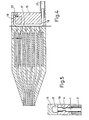
- a module is now produced, in which, for example, six nozzle channels 1 bent in a precisely defined manner, including their drive elements 2, outlet nozzles 3 and damping members 4, are combined in a block 10.
- the exemplary embodiment according to FIG. 2 shows that this can be done, for example, with a casting resin.
- the drive elements 2 themselves are not cast in, in order to keep free access to them, not to hinder their movements by casting resin or other fixings, and also to isolate them mechanically from one another.
- the drive elements can also be cast in the plastic block 10. Then, however, the change described later and the advantages mentioned must be dispensed with. It is therefore expedient to only summarize a module the nozzle channels themselves.
- the individual nozzle channels are poured in a mold.
- the holder in the region of the outlet nozzles 3 can be carried out in a known manner by means of a holding comb 12 or a perforated plate which ensures the required nozzle spacing.
- This bracket 12 is cast together with the individual nozzle channels 1.
- the nozzle channels 1 are placed in a divisible holder, not shown, of the casting mold in such a way that the drive elements 2 are located in the recess 14 formed by the holder and the nozzle channels protrude on both sides of this recess 14.
- the feedthroughs in the mold for the nozzle channels 10 must be tight so that no casting resin reaches the drive elements 2.
- nozzle channels 1 now held in the areas of the outlet nozzles 3 and the drive elements 2 are placed in a mold, not shown, which determines the shape of the module, care being taken that no casting resin can penetrate into the interior of the nozzle channels 1.
- This can be done in a known manner by flexible sealing materials, e.g. Silicone rubber, reach.
- the casting mold can also be designed such that it already ends at the section line 13.
- shrinkage tolerances cannot be ruled out, there is a risk that the edge will not be flat and the ends of the nozzle channels will protrude somewhat from this edge surface. As described later, this area must be sealed against the distribution channel.
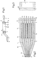
- the tubular distributor channel is produced in a separate operation (Fig. 3).
- a U-shaped channel .16 is formed in a plastic block 15, e.g. by casting a correspondingly shaped wire, which is then etched out, or in another suitable form.
- the mold not shown here is also kept somewhat larger.
- the plastic block 15 is then brought into the desired shape along the cutting line 20 in the region of this web.
- This section line 20 is to be laid so that the web of the distribution channel is open to the outside. At least in the area of the web, the distribution channel is larger in cross section than the cross section of the individual nozzle channels 1 and runs perpendicular to these.
- the U-shaped channel 16 consists of the web 17 as the actual distribution channel and of the legs 18 and 19.
- the feed line 21 for the writing liquid is connected to the leg 18.
- the leg 19 contains the venting device 22.
- This module is already a simple writing head with which characters can be constructed in a mosaic-like manner.
- the print head allows liquid to be filled in easily without trapping gas bubbles. This is achieved in that there are no disruptive edges in the course of the liquid paths.
- the ink supply can also take place in such a way that the distribution channel 17 is led straight up and down out of the block 15.
- the drive elements 2 are freely accessible on the finished write head. If at the same time one possibility is provided on each drive element 2 to trim it, the entire write head, i.e. set all of its nozzle channels 1 to the same properties with the same control impulses for all channels. When using piezoelectric transducers, this can be done in a simple manner by partially burning away or etching away one of the electrodes 5 or 6. The efficiency of the individual drive elements can thus be set so that all nozzle channels 1 react in the same way to the same control pulse.
- the module can be made as a plate-like element put. If several such modules are stacked and the outlet nozzles 3 of the one module are shifted in a suitable manner, multiple writing heads can be produced with many drop generators working simultaneously, which at the same time allow many matrix patterns determined by the arrangement of the outlet nozzles.
Landscapes
- Particle Formation And Scattering Control In Inkjet Printers (AREA)
Applications Claiming Priority (2)
| Application Number | Priority Date | Filing Date | Title |
|---|---|---|---|
| DE19813104077 DE3104077A1 (de) | 1981-02-06 | 1981-02-06 | "schreibkopf fuer tintenstrahldrucker" |
| DE3104077 | 1981-02-06 |
Publications (3)
| Publication Number | Publication Date |
|---|---|
| EP0057956A2 true EP0057956A2 (fr) | 1982-08-18 |
| EP0057956A3 EP0057956A3 (en) | 1983-08-03 |
| EP0057956B1 EP0057956B1 (fr) | 1986-04-23 |
Family
ID=6124173
Family Applications (1)
| Application Number | Title | Priority Date | Filing Date |
|---|---|---|---|
| EP82200100A Expired EP0057956B1 (fr) | 1981-02-06 | 1982-01-28 | Tête à écrire pour une imprimante à jet d'encre |
Country Status (5)
| Country | Link |
|---|---|
| US (1) | US4414552A (fr) |
| EP (1) | EP0057956B1 (fr) |
| JP (1) | JPS57148663A (fr) |
| CA (1) | CA1176689A (fr) |
| DE (2) | DE3104077A1 (fr) |
Families Citing this family (10)
| Publication number | Priority date | Publication date | Assignee | Title |
|---|---|---|---|---|
| DE3234408C2 (de) * | 1982-09-16 | 1986-01-09 | Siemens AG, 1000 Berlin und 8000 München | Schreibkopf mit piezoelektrischen Antriebselementen für Tintenschreibeinrichtungen |
| US4727012A (en) * | 1984-10-25 | 1988-02-23 | Siemens Aktiengesellschaft | Method of manufacture for print heads of ink jet printers |
| JPH03169636A (ja) * | 1989-11-30 | 1991-07-23 | Juki Corp | インク噴射ノズル装置 |
| IT1272050B (it) * | 1993-11-10 | 1997-06-11 | Olivetti Canon Ind Spa | Dispositivo stampante parallelo con struttura modulare e relativo procedimento di realizzazione. |
| US5958342A (en) * | 1996-05-17 | 1999-09-28 | Incyte Pharmaceuticals, Inc. | Jet droplet device |
| US5901425A (en) * | 1996-08-27 | 1999-05-11 | Topaz Technologies Inc. | Inkjet print head apparatus |
| US7163284B2 (en) * | 2001-12-12 | 2007-01-16 | Industrial Technology Research Institute | Multi-reagent inkjet cartridge |
| KR20060112870A (ko) * | 2005-04-28 | 2006-11-02 | 삼성전자주식회사 | 압전 소자 및 이를 갖는 프린터 헤드 |
| GB2549720A (en) * | 2016-04-25 | 2017-11-01 | Jetronica Ltd | Industrial printhead |
| CN109664616A (zh) * | 2018-11-29 | 2019-04-23 | 佛山市南海永恒头盔制造有限公司 | 异形物体表面印刷喷头 |
Family Cites Families (14)
| Publication number | Priority date | Publication date | Assignee | Title |
|---|---|---|---|---|
| US3832579A (en) * | 1973-02-07 | 1974-08-27 | Gould Inc | Pulsed droplet ejecting system |
| US4158847A (en) * | 1975-09-09 | 1979-06-19 | Siemens Aktiengesellschaft | Piezoelectric operated printer head for ink-operated mosaic printer units |
| DE2543397C3 (de) * | 1975-09-29 | 1982-07-15 | Siemens AG, 1000 Berlin und 8000 München | Vorrichtung zum Dämpfen von Flüssigkeitsschwingungen in Tintenversorgungssystemen von Tintenmosaikschreibeinrichtungen |
| SE7603784L (sv) * | 1975-09-29 | 1977-03-30 | Siemens Ag | Anordning for kontaktering av elektriska komponenter for ingjutning i arbetsstycken |
| DE2543452C3 (de) * | 1975-09-29 | 1980-06-12 | Siemens Ag, 1000 Berlin Und 8000 Muenchen | Entlüftungsvorrichtung für Tintenversorgungssysteme von Tintenstrahlschreibeinrichtungen |
| US4047186A (en) * | 1976-01-26 | 1977-09-06 | International Business Machines Corporation | Pre-aimed nozzle for ink jet recorder and method of manufacture |
| US4216477A (en) * | 1978-05-10 | 1980-08-05 | Hitachi, Ltd. | Nozzle head of an ink-jet printing apparatus with built-in fluid diodes |
| JPS54148533A (en) * | 1978-05-15 | 1979-11-20 | Seiko Epson Corp | Head of ink jet recorder |
| DE2835262C2 (de) * | 1978-08-11 | 1982-09-09 | Dr.-Ing. Rudolf Hell Gmbh, 2300 Kiel | Ansteuerung eines Tintenstrahl-Aufzeichnungsorgans |
| JPS5561474A (en) * | 1978-11-01 | 1980-05-09 | Ricoh Co Ltd | Multi-head recording apparatus |
| JPS55117665A (en) * | 1979-03-01 | 1980-09-10 | Ricoh Co Ltd | Ink jet integrated head |
| JPS55150376A (en) * | 1979-05-14 | 1980-11-22 | Canon Inc | Liquid ejection recording head |
| JPS5839069B2 (ja) * | 1979-05-29 | 1983-08-27 | セイコーエプソン株式会社 | インクジェットヘッドの製造方法 |
| JPS5677156A (en) * | 1979-11-28 | 1981-06-25 | Ricoh Co Ltd | Ink jet recorder |
-
1981
- 1981-02-06 DE DE19813104077 patent/DE3104077A1/de not_active Withdrawn
-
1982
- 1982-01-28 EP EP82200100A patent/EP0057956B1/fr not_active Expired
- 1982-01-28 DE DE8282200100T patent/DE3270704D1/de not_active Expired
- 1982-02-03 US US06/345,276 patent/US4414552A/en not_active Expired - Fee Related
- 1982-02-04 CA CA000395523A patent/CA1176689A/fr not_active Expired
- 1982-02-05 JP JP57016502A patent/JPS57148663A/ja active Pending
Also Published As
| Publication number | Publication date |
|---|---|
| DE3270704D1 (en) | 1986-05-28 |
| US4414552A (en) | 1983-11-08 |
| DE3104077A1 (de) | 1982-09-09 |
| EP0057956A3 (en) | 1983-08-03 |
| JPS57148663A (en) | 1982-09-14 |
| EP0057956B1 (fr) | 1986-04-23 |
| CA1176689A (fr) | 1984-10-23 |
Similar Documents
| Publication | Publication Date | Title |
|---|---|---|
| DE2532037C2 (de) | Tintentröpfchen-Aufzeichnungsvorrichtung | |
| DE2543451C2 (de) | Piezoelektrisch betriebener Schreibkopf für Tintenmosaikschreibeinrichtungen | |
| DE3877480T2 (de) | Verfahren zur herstellung von duesen fuer tintenstrahldrucker. | |
| DE60128506T2 (de) | Tintenstrahlkopf | |
| DE3524000B4 (de) | Flüssigkeitsstrahlaufzeichnungskopf | |
| DE3005394C2 (fr) | ||
| DE69623827T2 (de) | Antriebseinheit | |
| DE60220846T2 (de) | Kontinuierlich arbeitender Tintenstrahldruckkopf | |
| DE3012720C2 (fr) | ||
| DE3787922T2 (de) | Tintenstrahldrucker. | |
| DE68907434T2 (de) | Tintenstrahlkopf. | |
| DE69129159T2 (de) | Tintenstrahlkopf | |
| DE69424131T2 (de) | Tintenstrahlaufzeichnungskopf, Tintenstrahleinheit und Tintenstrahlgerät mit diesem Aufzeichnungskopf | |
| DE69514675T2 (de) | Tintenstrahlkopf und düsenplatte dafür | |
| DE69934469T2 (de) | Druckköpfe | |
| DE3311956A1 (de) | Farbstrahl-druckerkopf | |
| DE3248087A1 (de) | Fluessigkeitsstrahlkopf | |
| DE69402738T2 (de) | Verbindungsanordnung hoher Dichte für Tintenstrahldruckkopf | |
| EP0135197A1 (fr) | Système de génération de gouttelettes pour dispositifs d'écriture à encre | |
| EP0436047A1 (fr) | Tête d'imprimante à jets de liquide pour imprimante à jets d'encre | |
| EP0121894B1 (fr) | Tête d'écriture commandée par piézo-électricité pour dispositifs d'écriture à mosaique d'encre | |
| DE2808275C2 (de) | Tintenstrahldruckkopf | |
| EP0150348B1 (fr) | Tête d'impression à jet d'encre | |
| DE69217879T2 (de) | Tintenstrahldruckkopf | |
| DE69407821T2 (de) | Herstellung eines farbstrahldruckkopfes mit zweikanalig ausgerichteter innenanordnung |
Legal Events
| Date | Code | Title | Description |
|---|---|---|---|
| PUAI | Public reference made under article 153(3) epc to a published international application that has entered the european phase |
Free format text: ORIGINAL CODE: 0009012 |
|
| 17P | Request for examination filed |
Effective date: 19820218 |
|
| AK | Designated contracting states |
Designated state(s): DE FR GB IT SE |
|
| RAP1 | Party data changed (applicant data changed or rights of an application transferred) |
Owner name: N.V. PHILIPS' GLOEILAMPENFABRIEKEN Owner name: PHILIPS PATENTVERWALTUNG GMBH |
|
| PUAL | Search report despatched |
Free format text: ORIGINAL CODE: 0009013 |
|
| AK | Designated contracting states |
Designated state(s): DE FR GB IT SE |
|
| GRAA | (expected) grant |
Free format text: ORIGINAL CODE: 0009210 |
|
| AK | Designated contracting states |
Kind code of ref document: B1 Designated state(s): DE FR GB IT SE |
|
| REF | Corresponds to: |
Ref document number: 3270704 Country of ref document: DE Date of ref document: 19860528 |
|
| ITF | It: translation for a ep patent filed | ||
| ET | Fr: translation filed | ||
| PLBE | No opposition filed within time limit |
Free format text: ORIGINAL CODE: 0009261 |
|
| STAA | Information on the status of an ep patent application or granted ep patent |
Free format text: STATUS: NO OPPOSITION FILED WITHIN TIME LIMIT |
|
| 26N | No opposition filed | ||
| PG25 | Lapsed in a contracting state [announced via postgrant information from national office to epo] |
Ref country code: GB Effective date: 19890128 |
|
| PG25 | Lapsed in a contracting state [announced via postgrant information from national office to epo] |
Ref country code: SE Effective date: 19890129 |
|
| GBPC | Gb: european patent ceased through non-payment of renewal fee | ||
| PG25 | Lapsed in a contracting state [announced via postgrant information from national office to epo] |
Ref country code: FR Free format text: LAPSE BECAUSE OF NON-PAYMENT OF DUE FEES Effective date: 19890929 |
|
| PG25 | Lapsed in a contracting state [announced via postgrant information from national office to epo] |
Ref country code: DE Effective date: 19891003 |
|
| REG | Reference to a national code |
Ref country code: FR Ref legal event code: ST |
|
| EUG | Se: european patent has lapsed |
Ref document number: 82200100.4 Effective date: 19891204 |