EP0058020B1 - Endoskope - Google Patents
Endoskope Download PDFInfo
- Publication number
- EP0058020B1 EP0058020B1 EP82300434A EP82300434A EP0058020B1 EP 0058020 B1 EP0058020 B1 EP 0058020B1 EP 82300434 A EP82300434 A EP 82300434A EP 82300434 A EP82300434 A EP 82300434A EP 0058020 B1 EP0058020 B1 EP 0058020B1
- Authority
- EP
- European Patent Office
- Prior art keywords
- eyepiece
- endoscope
- optical axis
- camera
- eccentricity
- Prior art date
- Legal status (The legal status is an assumption and is not a legal conclusion. Google has not performed a legal analysis and makes no representation as to the accuracy of the status listed.)
- Expired
Links
- 230000003287 optical effect Effects 0.000 claims abstract description 54
- 230000002093 peripheral effect Effects 0.000 claims description 3
- 230000004438 eyesight Effects 0.000 description 8
- IJGRMHOSHXDMSA-UHFFFAOYSA-N Atomic nitrogen Chemical compound N#N IJGRMHOSHXDMSA-UHFFFAOYSA-N 0.000 description 2
- 238000006073 displacement reaction Methods 0.000 description 2
- 239000011230 binding agent Substances 0.000 description 1
- 230000015572 biosynthetic process Effects 0.000 description 1
- 238000010276 construction Methods 0.000 description 1
- 230000008878 coupling Effects 0.000 description 1
- 238000010168 coupling process Methods 0.000 description 1
- 238000005859 coupling reaction Methods 0.000 description 1
- 238000003745 diagnosis Methods 0.000 description 1
- 239000000835 fiber Substances 0.000 description 1
- 239000011261 inert gas Substances 0.000 description 1
- 238000007689 inspection Methods 0.000 description 1
- 230000013011 mating Effects 0.000 description 1
- 230000004048 modification Effects 0.000 description 1
- 238000012986 modification Methods 0.000 description 1
- 229910052757 nitrogen Inorganic materials 0.000 description 1
- 229910000679 solder Inorganic materials 0.000 description 1
- 210000002105 tongue Anatomy 0.000 description 1
- 210000001835 viscera Anatomy 0.000 description 1
- 230000004304 visual acuity Effects 0.000 description 1
Images
Classifications
-
- A—HUMAN NECESSITIES
- A61—MEDICAL OR VETERINARY SCIENCE; HYGIENE
- A61B—DIAGNOSIS; SURGERY; IDENTIFICATION
- A61B1/00—Instruments for performing medical examinations of the interior of cavities or tubes of the body by visual or photographical inspection, e.g. endoscopes; Illuminating arrangements therefor
- A61B1/04—Instruments for performing medical examinations of the interior of cavities or tubes of the body by visual or photographical inspection, e.g. endoscopes; Illuminating arrangements therefor combined with photographic or television appliances
Definitions
- This invention relates to endoscopes of the hard type, i.e. having a rigid casing, in which there is mounted an optical system to provide means for inspection or photographic recording of the interior of cavities, for example body cavities in the case of medical use, the endoscope having a relay lens system in the observing optical system, and an eye-piece cap which can be used to locate a photographic or television camera objective.
- a camera objective is fitted with an adapter to engage and locate upon the eyepiece of an endoscope in order that a body cavity in which the front of the endoscope is inserted can be photographed for study and diagnosis, for example.
- the optical axis of the endoscope optical system and the optical axis of the camera objective do not coincide, but are mutually off-set, then there will be some deflection of the image in the camera, which may lead to the loss of information at a marginal zone. Therefore, means may be provided on the camera to correct for any eccentricity of the optical axis of the endoscope.
- the Japanese Utility Model No. 126801/1980 proposes the displacement of the endoscope optical axis with respect to an endoscope eyepiece by use of an image guide fixing device for the eyepiece of a soft endoscope, in which the optical system for transmitting images to be observed is formed of a fibre-optic bundle, the above-mentioned eccentricity being forcibly corrected by displacement of the fixing device, for example, by a three-point locking screw grip, utilising the flexibility of the fibre bundle, and any consequential inclination of the end face of the bundle then being corrected by adjusting screws mounted in the fixing device.
- a hard endoscope in which images are transmitted by a rigid relay lens system, it is impossible to easily adjust the image transmitting optical system by force, as in the above-mentioned device disclosed in Japanese Utility Model No. 126801/1980.
- An object of the present invention is to facilitate the taking of photographs with a hard endoscope using a removable camera fitted to the eyepiece part, by standardising the endoscope to correct for any eccentricity, using correcting means which mutually align the optical axis of the observing optical system and the optical axis of the camera, these correcting means being provided in the endoscope eyepiece structure and enabling a camera with a correctly centred adaptor to be used with any such endoscope with no alignment problems.
- the invention consists in a hard endoscope having a relay lens optical system to transmit an observed image to an eyepiece to which a camera may be fitted by means of an adaptor that is mounted on the camera to be concentric with the optical axis of the camera objective, characterised in that said eyepiece is provided with adjustable eccentricity correction means for effectively displacing the outer periphery of the eyepiece with respect to the endoscope optical axis and so standardise the endoscope by making the optical axis of the rigid- structured observing optical system of the hard endoscope substantially concentric with said outer periphery, whereby the optical axis of the fitted camera will be effectively aligned with the optical axis of the observing optical system of the hard endoscope.
- Any eccentricity of the optical axis of the observing optical system of the hard endoscope with respect to the optical axis of the camera can then be easily controlled so as to be minimised or eliminated, without applying any undesirable force to the optical system of the endoscope.
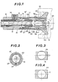
- an operating part 11 of an endoscope contains a relay lens 13 fitted within a tube 12 and arranged to extend towards the rear of an input objective (not shown) at the front end of the inserted part of the endoscope, and a light guide 15 connected to a light source (not shown) via a coupling 14 and a flexible cable (not shown).
- the light guide 15 is fitted on the outer periphery of the tube 12 and it also extends to the front end of the inserted part of the endoscope.
- An outer tube 16' is screwed to the rear of the body 16 of the operating part 11 and sealed by an 0-ring 17.
- An eyepiece frame 19 sealed by an eyepiece window 18 is screwed to the rear end of this outer tube 16'.
- the interior of the endoscope is filled with an inert gas, such as nitrogen, to prevent frosting of the optical system.
- a photographic camera having an objective lens 20 is removably fitted to the eyepiece frame 19 on the body 16 by an adapter 21 set on the camera with respect to the lens 20, so that, for example, an internal organ within the body cavity in which the inserted part of the endoscope is inserted can be illuminated via the light guide 15, and an image transmitted through the input objective (not illustrated) at the front end of the inserted part of the endoscope and passed by the relay lens 13 to be focused in the position of a vision field mask 22, and thus form a focused image on a film 24 in the case of a photographic camera, the image being fed out vie the eyepiece objective 23 and the camera lens 20.
- the relay lens 13 is secured at its rear end by a lens fixing nut 26 screwed to the rear inner periphery of a fixing frame 25 that is soldered on the rear outer periphery of the tube 12. Further, a focusing frame 28 for the eyepiece objective 23 is screwed to this fixing frame 25 and fixed in position by a lock nut 27.
- a fitting frame 29 carries the vision field mask 22 at its front end and the objective 23 at its rear end, and is fixed to the focusing frame 28 by a clamping screw 30.
- An optical system holding part 31 having a male screw thread on its outer periphery at its front end is screwed onto a female screw thread formed on the inner periphery at the rear of the operating part body 16, this holding part 31 having tapered holding pieces 32 forming tongues extending inwardly and rearwardly.
- the focusing frame 28 is held by the inner periphery of these holding pieces 32, and is fixed with a binder or by solder so that the observing optical system is held securely fixed without applying any undesirable force.
- the fixed position of the observing optical system may be eccentric with respect to the periphery of the eyepiece, but the eccentricity cannot be corrected by the application of a transverse force, as in a soft endoscope using a fibre-optic bundle, and furthermore any alignment errors introduced by the assembly together of the focusing frame 28 fixed by the lock nut 27 of the focusing means, the eyepiece frame 29 and the photographic adapter 21 will be accumulative, so that in some cases the eccentricity x, that is, the deviation between the centre of the eyepiece frame 19 and the axis of the eyepiece lens 23 may reach 1 mm, for exmaple.
- the deviation x will be produced between the optical axis of the observing optical system of the hard endoscope and the optical axis of the camera, and, as shown in Figure 3 if the eccentricity x is produced transverse to the longitudinal axis of a film 24 in a 35 mm camera, for example, the centre axis of an image G will be offset and lead to the loss of detail in the marginal zone that is shown shaded.
- a rotatable eccentric centering frame 33 is fitted between the outer tube 16' and the eyepiece frame 19 as shown in Figure 2, so that the centering frame 33 can be rotated to a setting in which the eccentricity x is substantially eliminated, and the image is central, on the longitudinal axis of the film stock, as the endoscope optical system axis is correctly positioned with respect to the centre of the outer peripheral circle of the centering frame 33, and the outer tube 16' and centering frame 33 can then be locked by a clamping screw 34.
- This construction thus enables such an eccentricity x to be minimized or eliminated.
- This centering adjustment may be carried out by using an eccentricity controlling jig (not illustrated) having a screen concentric with the outer peripheral cirle of the centering frame 33, and having crossed lines marking the centre position of the focusing lens.
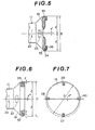
- Figure 5 shows a second embodiment of the invention, in which an eccentric centering ring 35 is fitted on the outer pheriphery of the eyepiece frame 19, and may be rotated to adjust for correction of any eccentricity x' so that the optical axis coincides with the centre of the eyepiece part, the fitting diameter D and radius / being indicated here to emphasise that the eccentricity x' can usually be completely corrected if a slight eccentricity in a direction normal to the eccentricity x' can be accepted.
- the ring 35 is held by a fixing frame 36 screwed to the eyepiece frame 19 so that the ring 35 can rotate, but not move away from the frame 19.
- the ring 35 is locked in position, when set, by a clamping screw 34.
- the eccentricity x' between the centre of the vision field mask 22, eyepiece 23, and eyepice frame 19 can be fully corrected by the proper rotational position of the centering ring 35. It may be advantageous to provide a key slot or flat on the adapter 21, to co-operate with a mating portion of the eyepiece frame 19, to identify the x-direction in either of the two embodiments described above.
- Figures 6 and 7 show a third embodiment of the invention, in which a set of eccentricity controlling screws are disposed around the periphery of the eyepiece frame 19.
- a set of eccentricity controlling screws are disposed around the periphery of the eyepiece frame 19.
- Figure 6 shows the diameter D and radius /, to emphasise that adjustment may be effected only with respect to one direction, as described with reference to Figure 4. However, it will be apparent from a consideration of Figure 7 that the provision of individual screws enables correction to be completely effective for any direction of deviation.
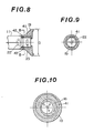
- FIGS 8 to 10 show a fourth embodiment of the invention, in which an eccentric ring 41 similar to the ring 33 or 35 of the first and second embodiments is provided, together with an eccentric eyepiece frame 19. Respective clamping screws 42 and 43 are provided.
- any eccentricity T between the image centre, or centre of the vision field mask 22, and the centre of the operating part body 16, any eccentricity Y between the operating part body 16 and the centering ring 41, and eccentricity Z between the centering ring 41 and the eyepiece frame 19 can be fully eliminated if T + Y ? Z, as it will then be possible to reduce all eccentricity to zero by adjusting the centre of the fitting diameter D of the eyepiece part to which the adapter is fitted and the image centre of the vision field mask 22 by rotating the respective eccentric rings.
- 35 mm. film cameras, 16 mm. cinematic cameras, and television cameras can be used with suitably designed adapters to fit on the eyepiece frame.
Landscapes
- Health & Medical Sciences (AREA)
- Life Sciences & Earth Sciences (AREA)
- Surgery (AREA)
- Biomedical Technology (AREA)
- Medical Informatics (AREA)
- Optics & Photonics (AREA)
- Pathology (AREA)
- Radiology & Medical Imaging (AREA)
- Biophysics (AREA)
- Engineering & Computer Science (AREA)
- Physics & Mathematics (AREA)
- Heart & Thoracic Surgery (AREA)
- Nuclear Medicine, Radiotherapy & Molecular Imaging (AREA)
- Molecular Biology (AREA)
- Animal Behavior & Ethology (AREA)
- General Health & Medical Sciences (AREA)
- Public Health (AREA)
- Veterinary Medicine (AREA)
- Endoscopes (AREA)
- Instruments For Viewing The Inside Of Hollow Bodies (AREA)
Claims (5)
Priority Applications (1)
| Application Number | Priority Date | Filing Date | Title |
|---|---|---|---|
| AT82300434T ATE18981T1 (de) | 1981-02-03 | 1982-01-28 | Endoskope. |
Applications Claiming Priority (2)
| Application Number | Priority Date | Filing Date | Title |
|---|---|---|---|
| JP14545/81 | 1981-02-03 | ||
| JP56014545A JPS57129407A (en) | 1981-02-03 | 1981-02-03 | Hard endoscope |
Publications (2)
| Publication Number | Publication Date |
|---|---|
| EP0058020A1 EP0058020A1 (de) | 1982-08-18 |
| EP0058020B1 true EP0058020B1 (de) | 1986-04-09 |
Family
ID=11864119
Family Applications (1)
| Application Number | Title | Priority Date | Filing Date |
|---|---|---|---|
| EP82300434A Expired EP0058020B1 (de) | 1981-02-03 | 1982-01-28 | Endoskope |
Country Status (5)
| Country | Link |
|---|---|
| US (1) | US4440157A (de) |
| EP (1) | EP0058020B1 (de) |
| JP (1) | JPS57129407A (de) |
| AT (1) | ATE18981T1 (de) |
| DE (1) | DE3270343D1 (de) |
Families Citing this family (19)
| Publication number | Priority date | Publication date | Assignee | Title |
|---|---|---|---|---|
| US4651201A (en) * | 1984-06-01 | 1987-03-17 | Arnold Schoolman | Stereoscopic endoscope arrangement |
| US4624243A (en) * | 1985-04-08 | 1986-11-25 | American Hospital Supply Corp. | Endoscope having a reusable eyepiece and a disposable distal section |
| US4905082A (en) * | 1987-05-06 | 1990-02-27 | Olympus Optical Co., Ltd. | Rigid video endoscope having a detachable imaging unit |
| US4854302A (en) * | 1987-11-12 | 1989-08-08 | Welch Allyn, Inc. | Video equipped endoscope with needle probe |
| US4844071A (en) * | 1988-03-31 | 1989-07-04 | Baxter Travenol Laboratories, Inc. | Endoscope coupler device |
| US5205280A (en) * | 1990-12-21 | 1993-04-27 | Mp Video, Inc. | Quick-release endoscopic coupling assembly |
| DE4105326A1 (de) * | 1991-02-21 | 1992-09-03 | Wolf Gmbh Richard | Endoskop mit proximal ankuppelbarer kamera |
| US5634881A (en) * | 1995-10-20 | 1997-06-03 | United States Surgical Corporation | Laparoscope |
| US5951463A (en) * | 1998-03-18 | 1999-09-14 | Clarus Medical Systems, Inc. | Hand-held endoscopic viewing system |
| DE19927631C1 (de) * | 1999-06-17 | 2000-11-23 | Winter & Ibe Olympus | Endoskopoptik |
| US7553278B2 (en) | 2005-06-01 | 2009-06-30 | Cannuflow, Inc. | Protective cap for arthroscopic instruments |
| JP5242221B2 (ja) * | 2008-03-31 | 2013-07-24 | オリンパス株式会社 | 撮像装置、電子内視鏡および撮像装置の組立方法 |
| AT513009B1 (de) * | 2012-06-11 | 2021-02-15 | Swarovski Optik Kg | Objektiv für ein Bildaufzeichnungsgerät |
| WO2014097717A1 (ja) * | 2012-12-17 | 2014-06-26 | オリンパスメディカルシステムズ株式会社 | 内視鏡及び内視鏡の製造方法 |
| CN103913835B (zh) * | 2012-12-29 | 2016-05-25 | 上海澳华光电内窥镜有限公司 | 一种可调节中心位置的目镜装置 |
| CN104873164B (zh) * | 2014-02-27 | 2017-04-19 | 北京威斯顿亚太光电仪器有限公司 | 一种基于led照明的可分离式光学硬管镜 |
| DE102016117805A1 (de) * | 2016-09-21 | 2018-03-22 | Henke-Sass, Wolf Gmbh | Endoskop und Verfahren zum Zentrieren eines Okulars in einem Hauptteil eines Endoskops |
| DE102018106469A1 (de) | 2018-03-20 | 2019-09-26 | Olympus Winter & Ibe Gmbh | Verfahren zum Zentrieren von optischen Elementen |
| DE102020205659B4 (de) | 2020-05-05 | 2023-11-02 | Richard Wolf Gmbh | Endoskop |
Family Cites Families (16)
| Publication number | Priority date | Publication date | Assignee | Title |
|---|---|---|---|---|
| US3638643A (en) * | 1967-10-17 | 1972-02-01 | Hotchkiss Instr Inc | Endoscope for photographic recording |
| US3740449A (en) * | 1971-06-24 | 1973-06-19 | Conn C Ltd | Electric organ with chord playing and rhythm systems |
| JPS5713294B2 (de) * | 1973-03-31 | 1982-03-16 | ||
| DE2358785C2 (de) * | 1973-11-26 | 1983-04-21 | Licentia Patent-Verwaltungs-Gmbh, 6000 Frankfurt | Justierbare Kopplungsvorrichtung für optische Bauelemente |
| JPS50136045A (de) * | 1974-04-15 | 1975-10-28 | ||
| GB1486681A (en) * | 1975-05-13 | 1977-09-21 | Standard Telephones Cables Ltd | Optical fibre termination |
| US4068932A (en) * | 1975-05-23 | 1978-01-17 | Canon Kabushiki Kaisha | Optical instrument for examining the eye fundus |
| US4102563A (en) * | 1975-12-01 | 1978-07-25 | Canon Kabushiki Kaisha | Eye fundus camera free from undesired reflected and diffused light beams |
| DE2640973C2 (de) * | 1976-09-11 | 1981-08-20 | Standard Elektrik Lorenz Ag, 7000 Stuttgart | Verbindungsvorrichtung für Lichtleiter |
| JPS53144193A (en) * | 1977-05-20 | 1978-12-15 | Canon Kk | Ophthalmologic machine having operating distance detector |
| US4181401A (en) * | 1978-03-24 | 1980-01-01 | S. C. Cabling, Inc. | Fiber optic waveguide connector |
| US4196990A (en) * | 1979-02-23 | 1980-04-08 | Polaroid Corporation | Adapter for coupling a photographic camera with a viewing device |
| US4369767A (en) * | 1979-05-25 | 1983-01-25 | Olympus Optical Co., Ltd. | Endoscope system |
| DE2923490C2 (de) * | 1979-06-09 | 1982-04-29 | Standard Elektrik Lorenz Ag, 7000 Stuttgart | Stecker für Lichtleitungsverbinder |
| US4264167A (en) * | 1980-02-04 | 1981-04-28 | Polaroid Corporation | Adapter for coupling a camera with a viewing device |
| JPS5782640A (en) * | 1980-11-10 | 1982-05-24 | Matsushita Seiko Co Ltd | Operation controlling device for air-conditioning unit |
-
1981
- 1981-02-03 JP JP56014545A patent/JPS57129407A/ja active Pending
-
1982
- 1982-01-28 AT AT82300434T patent/ATE18981T1/de active
- 1982-01-28 EP EP82300434A patent/EP0058020B1/de not_active Expired
- 1982-01-28 DE DE8282300434T patent/DE3270343D1/de not_active Expired
- 1982-02-02 US US06/344,952 patent/US4440157A/en not_active Expired - Lifetime
Also Published As
| Publication number | Publication date |
|---|---|
| JPS57129407A (en) | 1982-08-11 |
| EP0058020A1 (de) | 1982-08-18 |
| DE3270343D1 (en) | 1986-05-15 |
| ATE18981T1 (de) | 1986-04-15 |
| US4440157A (en) | 1984-04-03 |
Similar Documents
| Publication | Publication Date | Title |
|---|---|---|
| EP0058020A1 (de) | Endoskope | |
| US6383131B1 (en) | Stereoscopic endoscope | |
| JP4716595B2 (ja) | 内視鏡装置及び内視鏡用光学アダプタの組立て方法 | |
| US6483535B1 (en) | Wide angle lens system for electronic imagers having long exit pupil distances | |
| US5027138A (en) | Dental camera system | |
| US6142932A (en) | Front end structure of stereoscopic endoscope including an elongated lens | |
| US6338711B1 (en) | Stereoscopic endoscope | |
| EP1801646B1 (de) | Digitales kamerasystem | |
| EP0335523A1 (de) | Endoskop-Kupplung | |
| WO1992007504A1 (en) | Ccd camera and method for fundus imaging | |
| US4930883A (en) | Photovisual star diagonal | |
| US4862199A (en) | Adjustable adapter for borescope and film/video camera | |
| US5194988A (en) | Device for correcting perspective distortions | |
| GB2068581A (en) | Optical system for endoscopes | |
| JPS6266220A (ja) | 内視鏡 | |
| JP4204890B2 (ja) | 映画撮影用カメラの対物レンズ | |
| JP3257641B2 (ja) | 立体視内視鏡装置 | |
| US4834516A (en) | Noninverting photo-microscope with variable power lenses | |
| DE69426246T2 (de) | Optische Vorrichtung mit einer Funktion zur Verhinderung von Bildzittern | |
| US5044728A (en) | Device for correcting perspective distortions | |
| JP3554398B2 (ja) | 内視鏡用立体視アダプター | |
| GB2155192A (en) | High speed tv camera | |
| JPH04252B2 (de) | ||
| JPH06331903A (ja) | テレビカメラ接続鏡筒 | |
| JPS63281115A (ja) | 内視鏡装置 |
Legal Events
| Date | Code | Title | Description |
|---|---|---|---|
| PUAI | Public reference made under article 153(3) epc to a published international application that has entered the european phase |
Free format text: ORIGINAL CODE: 0009012 |
|
| AK | Designated contracting states |
Designated state(s): AT BE CH DE FR GB IT NL SE |
|
| 17P | Request for examination filed |
Effective date: 19821204 |
|
| GRAA | (expected) grant |
Free format text: ORIGINAL CODE: 0009210 |
|
| AK | Designated contracting states |
Kind code of ref document: B1 Designated state(s): AT BE CH DE FR GB IT LI NL SE |
|
| PG25 | Lapsed in a contracting state [announced via postgrant information from national office to epo] |
Ref country code: NL Effective date: 19860409 Ref country code: LI Effective date: 19860409 Ref country code: IT Free format text: LAPSE BECAUSE OF FAILURE TO SUBMIT A TRANSLATION OF THE DESCRIPTION OR TO PAY THE FEE WITHIN THE PRESCRIBED TIME-LIMIT;WARNING: LAPSES OF ITALIAN PATENTS WITH EFFECTIVE DATE BEFORE 2007 MAY HAVE OCCURRED AT ANY TIME BEFORE 2007. THE CORRECT EFFECTIVE DATE MAY BE DIFFERENT FROM THE ONE RECORDED. Effective date: 19860409 Ref country code: FR Free format text: THE PATENT HAS BEEN ANNULLED BY A DECISION OF A NATIONAL AUTHORITY Effective date: 19860409 Ref country code: CH Effective date: 19860409 Ref country code: BE Effective date: 19860409 Ref country code: AT Effective date: 19860409 |
|
| REF | Corresponds to: |
Ref document number: 18981 Country of ref document: AT Date of ref document: 19860415 Kind code of ref document: T |
|
| PG25 | Lapsed in a contracting state [announced via postgrant information from national office to epo] |
Ref country code: SE Effective date: 19860430 |
|
| REF | Corresponds to: |
Ref document number: 3270343 Country of ref document: DE Date of ref document: 19860515 |
|
| REG | Reference to a national code |
Ref country code: CH Ref legal event code: PL |
|
| EN | Fr: translation not filed | ||
| NLV1 | Nl: lapsed or annulled due to failure to fulfill the requirements of art. 29p and 29m of the patents act | ||
| PLBE | No opposition filed within time limit |
Free format text: ORIGINAL CODE: 0009261 |
|
| STAA | Information on the status of an ep patent application or granted ep patent |
Free format text: STATUS: NO OPPOSITION FILED WITHIN TIME LIMIT |
|
| 26N | No opposition filed | ||
| GBPC | Gb: european patent ceased through non-payment of renewal fee | ||
| PG25 | Lapsed in a contracting state [announced via postgrant information from national office to epo] |
Ref country code: GB Effective date: 19881121 |
|
| PGFP | Annual fee paid to national office [announced via postgrant information from national office to epo] |
Ref country code: DE Payment date: 19960126 Year of fee payment: 15 |
|
| PG25 | Lapsed in a contracting state [announced via postgrant information from national office to epo] |
Ref country code: DE Effective date: 19971001 |