EP0058122A1 - Dispositif de correction de balourd de rotor de turbomachines - Google Patents
Dispositif de correction de balourd de rotor de turbomachines Download PDFInfo
- Publication number
- EP0058122A1 EP0058122A1 EP82400223A EP82400223A EP0058122A1 EP 0058122 A1 EP0058122 A1 EP 0058122A1 EP 82400223 A EP82400223 A EP 82400223A EP 82400223 A EP82400223 A EP 82400223A EP 0058122 A1 EP0058122 A1 EP 0058122A1
- Authority
- EP
- European Patent Office
- Prior art keywords
- cylindrical
- shaft
- bore
- transverse wall
- correction device
- Prior art date
- Legal status (The legal status is an assumption and is not a legal conclusion. Google has not performed a legal analysis and makes no representation as to the accuracy of the status listed.)
- Granted
Links
- 238000012937 correction Methods 0.000 claims abstract description 13
- 230000000295 complement effect Effects 0.000 claims abstract description 7
- 230000002093 peripheral effect Effects 0.000 claims abstract description 5
- 239000007787 solid Substances 0.000 claims 1
- 230000000903 blocking effect Effects 0.000 description 4
- 238000003754 machining Methods 0.000 description 2
- 210000002105 tongue Anatomy 0.000 description 2
- 238000010276 construction Methods 0.000 description 1
- 238000007796 conventional method Methods 0.000 description 1
- 238000005259 measurement Methods 0.000 description 1
- 238000000034 method Methods 0.000 description 1
- 238000012360 testing method Methods 0.000 description 1
Images

Classifications
-
- F—MECHANICAL ENGINEERING; LIGHTING; HEATING; WEAPONS; BLASTING
- F01—MACHINES OR ENGINES IN GENERAL; ENGINE PLANTS IN GENERAL; STEAM ENGINES
- F01D—NON-POSITIVE DISPLACEMENT MACHINES OR ENGINES, e.g. STEAM TURBINES
- F01D5/00—Blades; Blade-carrying members; Heating, heat-insulating, cooling or antivibration means on the blades or the members
- F01D5/02—Blade-carrying members, e.g. rotors
- F01D5/027—Arrangements for balancing
-
- F—MECHANICAL ENGINEERING; LIGHTING; HEATING; WEAPONS; BLASTING
- F16—ENGINEERING ELEMENTS AND UNITS; GENERAL MEASURES FOR PRODUCING AND MAINTAINING EFFECTIVE FUNCTIONING OF MACHINES OR INSTALLATIONS; THERMAL INSULATION IN GENERAL
- F16F—SPRINGS; SHOCK-ABSORBERS; MEANS FOR DAMPING VIBRATION
- F16F15/00—Suppression of vibrations in systems; Means or arrangements for avoiding or reducing out-of-balance forces, e.g. due to motion
- F16F15/32—Correcting- or balancing-weights or equivalent means for balancing rotating bodies, e.g. vehicle wheels
-
- Y—GENERAL TAGGING OF NEW TECHNOLOGICAL DEVELOPMENTS; GENERAL TAGGING OF CROSS-SECTIONAL TECHNOLOGIES SPANNING OVER SEVERAL SECTIONS OF THE IPC; TECHNICAL SUBJECTS COVERED BY FORMER USPC CROSS-REFERENCE ART COLLECTIONS [XRACs] AND DIGESTS
- Y10—TECHNICAL SUBJECTS COVERED BY FORMER USPC
- Y10T—TECHNICAL SUBJECTS COVERED BY FORMER US CLASSIFICATION
- Y10T74/00—Machine element or mechanism
- Y10T74/21—Elements
- Y10T74/211—Eccentric
Definitions
- the invention relates to a device for correcting the imbalance of a turbine engine rotor.
- the balancing of a mobile is usually obtained by removing or adding a certain mass of material at a determined distance from the axis and in a defined direction.
- French patent 2,272,260 proposes a device for correcting the imbalance of a rotor disc constituted by a number of masses arranged at the periphery of the disc against the rim in which the grooves holding the blade roots are machined.
- the balancing weights are in the form of rectangular parallelepipeds, one of the large faces of which bears tongues.
- the tongues are housed in radial grooves provided on the lateral faces of coplanar hooks with the radial face of the rim.
- the masses are held in the radial direction between the platform of the blades and an elastic ring, the ring being placed under the masses between the hooks and the face of the disc.
- This device makes it possible to obtain a precise balancing both in value and in direction and allows the possible disassembly of the blades without presenting any particular difficulties.
- This disc-by-disc balancing leaves a residual residual imbalance of low value at the level of the rotor bearings which may be determined on a direct or direct basis, for example, by the device described in French patent 1,477,752.
- the interior of which are arranged two masses in the form of coaxial circular sectors, angularly movable relative to one another.
- the housing is inserted into the hollow shaft at the level of the bearing.
- the adjustment is made using a suitable tool passing through the hollow shaft and by successive tests, by starting the reactor. A curve is thus established which makes it possible to determine the value of the balancing mass and its position.
- the final balancing is carried out by a conventional method by adding or removing material at the periphery of a disc.
- the invention proposes to compensate for the residual imbalance as close as possible to the bearings and relates to a correction device comprising in the bore of the shaft peripheral grooves and a transverse wall carrying fixing means fixed directly or indirectly in the axis of the shaft and also comprising a balancing part.
- This balancing piece is formed by a hollow cylindrical body carrying, on its outer surface, grooves provided to cooperate with the grooves of the shaft bore and, at one end, a bottom having complementary fixing means.
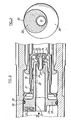
- FIG. 1 represents a partial view, in section, of a part of a turbomachine comprised between the low pressure and high pressure compressors at the level of the bearing of the rotor shaft.
- the shaft is made up of several parts which are joined together by mechanical means, an example of which is given in the figure.
- the shaft section 2 in its part engaged with the shaft section 1, is supported by a bearing 3 consisting of a ball bearing, the outer rings 4 of which are fixed indirectly to the casing of the turbomachine.
- the shaft sections 1 and 2 are hollow and the shaft section 1 has inside a recess 5 on the edge of which abuts the collar 6 of a clamping ring 7 whose threaded end 8 is screwed in an internal thread 9 of the shaft section 2 of the high pressure compressor.
- a locking piece 10 is provided which has grooves on its outer surface.
- a first ring of grooves 11 cooperates with corresponding grooves provided in the bore of the shaft section 1 and a second ring 12 cooperates with grooves provided in the bore of the clamping ring 7.
- the end of the workpiece blocking 10 is held in a bore 13 of the ring 7 and carries a threaded portion 14 on which is screwed a ring 15 which blocks the part 10, against the action of the spring 16, in the clamping ring 7. Due to the small thickness of the walls of the blocking piece 10, it comprises approximately mid-length a transverse wall 17.
- a ring 18 of splines in which a tool is introduced making it possible to screw or unscrew the thread 8 of the ring by a sufficient fraction of a turn to the alignment of the can grooves of the part 10 with those of the ring 7 and of the shaft section 1.
- the shaft sections 1 and 2 are also secured by a splined assembly 11a.
- connection method describes low pressure and high pressure sections of the compressor shaft provides a part (part 10) particularly well suited to constitute a part of the unbalance correction device according to the invention.
- the elements of room 10 necessary for the invention are the transverse wall 17 and the groove ring 18.
- the connecting shaft between the low pressure compressor and the high pressure compressor should include approximately at the level of the bearing and in the bore a transverse wall and peripheral grooves. These two elements may be provided directly for machining in the shaft or be carried by a part capable of being secured to the shaft.
- the transverse wall carries at its center fixing means 19 constituted, for example, by a stud whose end is threaded. On this threaded end 20 is fixed a balancing piece 21.
- the piece consists of a hollow cylindrical body 22 and a head 23 at least partially cylindrical.
- the body has on its outer surface grooves 24 provided to cooperate with the grooves 18 secured directly or indirectly to the shaft.
- a bottom 25 having complementary fixing means 26 cooperating with the fixing means 19.
- These complementary means consist of an orifice with a diameter corresponding to the end of the stud. 19 and a captive nut 27 or not.
- the head 23 has a cylindrical part 28 and an eccentric part 29 crossed by the extension of the bore 31 of the hollow cylindrical body.
- the eccentric part 29 is in the form of a disc, one face of which is integral with the face of the cylindrical part and whose diameter is at least equal to the sum of the radii of the cylindrical part 28 and of the bore 31.
- the cylindrical part and the eccentric part are tangent at a point 30 of their outer edges.
- the eccentric part is realized the approximate shape of a rectangular parallelepiped whose small end faces respectively have the shape of a cylindrical segment extending the cylindrical face of the cylindrical part 28 and a cylindrical segment extending the cylindrical face of the bore 31.
- the fastening means 19 are constituted by a boQon whose part 32 below the head is of polygonal shape, square for example, and enters a corresponding opening 33 of the transverse wall 17
- the body of the bolt is held in place in the wall 17 by a nut 34, which also serves as a support piece against which the balancing piece 21 will be tightened in the manner previously described.
- Part 28 has a groove 35 in which an O-ring 36 is housed.
- the implementation of the unbalance correction device according to the invention is as follows.
- the balancing part 21 is machined so that the head 23 and more particularly the eccentric part 29, has a mass which is a function of its thickness greater than the expected unbalance. Using a device conforming, for example to patent 1 477 752, the value and direction of the residual unbalance are determined. The excess mass is then removed by machining from the eccentric part (represented by the hatched part) to bring it to the residual unbalance value.
- the balancing piece 21 is introduced into the shaft 1 and the eccentric part is angularly positioned according to the prior measurements to compensate for the residual unbalance. The splines of the balancing piece 21 are engaged in the splines of the shaft bore and the piece 21 is blocked by the nut 27 on the transverse wall 17.
- the invention is of course not limited to the embodiment described which is applied to a turbomachine of the type unibody, because it can also be applied to a double-body or triple-body type turbomachine and in this case, the shaft section 1 becomes the low-pressure shaft of the machine.
Landscapes
- Engineering & Computer Science (AREA)
- General Engineering & Computer Science (AREA)
- Mechanical Engineering (AREA)
- Physics & Mathematics (AREA)
- Acoustics & Sound (AREA)
- Aviation & Aerospace Engineering (AREA)
- Turbine Rotor Nozzle Sealing (AREA)
- Structures Of Non-Positive Displacement Pumps (AREA)
Abstract
Description
- L'invention concerne un dispositif de correction de balourd de rotor de turbomachines.
- Les parties tournantes des turbomachines sont généralement équilibrées avec soin lors de leur construction, toutefois, il arrive que, après montage des différents étages déjà équilibrés, les moments résiduels soient suffisants pour provoquer de légères déformations de l'arbre en rotation. Ces déformations engendrent aux grandes vitesses des vibrations et des contraintes qui affectent gravement la durée de vie de la turbomachine.
- L'équilibrage d'un mobile est ordinairement obtenu par enlèvement ou apport d'une certaine masse de matière à une distance déterminée de l'axe et dans une direction définie.
- Le brevet français 2 272 260 propose un dispositif de correction du balourd d'un disque de rotor constitué par un certain nombre de masses disposées à la périphérie du disque contre la jante dans laquelle sont usinées les rainures maintenant les pieds d'aube. Les masses d'équilibrage se présentent sous la forme de parallélépipèdes rectangles dont.une des grandes faces porte des languettes. Les languettes se logent dans des gorges radiales prévues sur les faces latérales de crochets coplanaires avec la face radiale de la jante. Les masses sont maintenues en direction radiale entre la plateforme des aubes et un anneau élastique, l'anneau étant placé sous les masses entre les crochets et la face du disque.
- Ce dispositif permet l'obtention d'un équilibrage précis tant en valeur qu'en direction et autorise le démontage éventuel des aubes sans présenter de difficultés particulières.
- Cet équilibrage disque par disque laisse toutefois subsister au niveau des paliers du rotor un balourd résiduel de faible valeur qui pout êtro détorminé on grandour ot diroction, par exemple, par le dispositif décrit dîme le brevet français 1 477 752. Ce dispositif comporte un boîtier à l'intérieur duquel sont disposées deux masses en forme de secteurs circulaires coaxiaux, mobiles angulairement l'un par rapport à l'autre. Le boîtier est introduit dans 1.'arbre creux au niveau du palier. A l'aide de moyens prévus pour faire tourner les masses l'une par rapport à l'autre, ou solidairement, on peut créer un balourd additionnel égal au balourd résiduel et choisir la direction du balourd additionnel pour compenser exactement le balourd résiduel. Le réglage se fait à l'aide d'un outillage convenable passant dans l'arbre creux et par essais successifs, en mettant le réacteur en marche. On établit ainsi une courbe permettant de déterminer la valeur de la masse d'équilibrage et sa position. A l'aide de ces données, on procède à l'équilibrage définitif par une méthode classique par apport ou enlèvement de matière à la périphérie d'un disque.
- La compensation se faisant dans un plan relativement éloigné du palier, les résultats ne sont pas aussi bons que l'on pouvait escompter et les vibrations, bien que diminuées, sont encore sensibles au niveau des paliers.
- L'invention se propose de compenser le balourd résiduel aussi près que possible des paliers et a pour objet un dispositif de correction comportant dans l'alésage de l'arbre des cannelures périphériques et une paroi transversale portant des moyens de fixation fixés directement ou indirectement dans l'axe de l'arbre et comportant également une pièce d'équilibrage. Cette pièce d'équilibrage est formée d'un corps cylindrique creux portant, sur sa surface extérieure, des cannelures prévues pour coopérer avec les cannelures de l'alésage de l'arbre et, à une extrémité, un fond présentant des moyens complémentaires de fixation coopérant avec les moyens de fixation portés par la paroi transversale, et d'une tête dont une partie cylindrique, prolongeant coaxialement l'autre extrémité du corps cylindrique creux et comportant un même alésage, porte une partie excentrée dont une de ses dimensions est au moins égale à la somme des rayons de la partie cylindrique et de l'alésage.
- Les explications et figures données ci-après à titre d'exemple permettront de comprendre comment peut être réalisée l'invention.
- - La figure 1 est une vue partielle en coupe de la partie d'une turbomachine comprise entre les compresseurs basse pression et haute pression au niveau d'un palier, l'arbre étant équipé d'un dispositif selon l'invention.
- - La figure 2 est une vue en coupe à grande échelle d'une forme de réalisation du dispositif de correction.
- - La figure 3 est une vue selon III de la pièce d'équilibrage de la figure 2.
- La figure 1 représente une vue partielle, en coupe d'une partie de turbomachine comprise entre les compresseurs basse pression et haute pression au niveau du palier de l'arbre du rotor. Afin de faciliter le montage et, comme il est connu, l'arbre est formé de plusieurs parties qui sont solidarisées par des moyens mécaniques dont un exemple est donné sur la figure.
- L'extrémité de la partie d'arbre 1 sur laquelle sont fixés directement ou indirectement les étages basse pression, pénètre dans la partie d'arbre 2 sur laquelle sont fixés les étages haute pression. Le tronçon d'arbre 2, dans sa partie en prise avec le tronçon d'arbre 1, est supporté par un palier 3 constitué d'un roulement à billes dont les bagues extérieures 4 sont fixées indirectement au carter de la turbomachine. Les tronçons d'arbre 1 et 2 sont creux et le tronçon d'arbre 1 présente à l'intérieur un chambrage 5 sur le bord duquel vient buter la collerette 6 d'une bague de serrage 7 dont l'extrémité filetée 8 vient se visser dans un filetage intérieur 9 du tronçon d'arbre 2 du compresseur haute pression. Afin d'empêcher la rotation d'un tronçon d'arbre par rapport à l'autre, il est prévu une pièce de blocage 10 présentant sur sa surface extérieure des cannelures. Une première couronne de cannelures 11 coopère avec des cannelures correspondantes prévues dans l'alésage du tronçon d'arbre 1 et une deuxième couronne 12 coopère avec des cannelures prévues dans l'alésage de la bague de serrage 7. L'extrémité de la pièce de blocage 10 est maintenue dans un alésage 13 de la bague 7 et porte une partie filetée 14 sur laquelle vient se visser une bague 15 qui bloque la pièce 10, contre l'action du ressort 16, dans la bague de serrage 7. Du fait de la faible épaisseur des parois de la pièce de blocage 10, elle comporte approximativement à mi- longueur une paroi transversale 17. Afin de mettre en prise les cannelures de la pièce de blocage 10 à la fois avec les cannelures de l'arbre 1 et avec celles de la bague de serrage 7, il est prévu dans l'alésage de la pièce de blocage une couronne 18 de cannelures dans laquelle on introduit un outil permettant de visser ou de dévisser le filetage 8 de la bague d'une fraction de tour suffisante à l'alignement des cannelures de la pièce 10 avec celles de la bague 7 et du tronçon d'arbre 1. Les tronçons d'arbre 1 et 2 sont également solidarisés par un assemblage à cannelures 11a.
- Le mode de liaison ci-dessus décrit des tronçons basse pression et haute pression de l'arbre de compresseur procure une pièce (la pièce 10) particulièrement bien adaptée pour constituer une partie du dispositif de correction de balourd selon l'invention. Les éléments de la pièce 10 nécessaires à l'invention sont la paroi transversale 17 et la couronne de cannelures 18.
- Selon une forme de réalisation quelconque de l'arbre de liai- 'son entre le compresseur basse pression et le compresseur haute pression; il devra comporter approximativement au niveau du palier et dans l'alésage une paroi transversale et des cannelures périphériques. Ces deux éléments pourront être prévus directement d'usinage dans l'arbre ou être portés par une pièce susceptible d'être solidarisée avec l'arbre.
- Selon l'invention, et comme représenté à plus grande échelle à la figure 2, la paroi transversale porte en son centre des moyens de fixation 19 constitués, par exemple, par un goujon dont l'extrémité est filetée. Sur cette extrémité filetée 20 vient se fixer une pièce d'équilibrage 21. Selon une forme de réalisation de l'invention, la pièce est constituée d'un corps cylindrique creux 22 et d'une tête 23 au moins partiellement cylindrique. Le corps présente sur sa surface extérieure des cannelures 24 prévues pour coopérer avec les cannelures 18 solidaires directement ou indirectement de l'arbre. A l'extrémité du corps, opposée à la tête, se trouve un fond 25 présentant des moyens complémentaires de fixation 26 coopérant avec les moyens de fixation 19. Ces moyens complémentaires sont constitués d'un orifice de diamètre correspondant à l'extrémité du goujon 19 et d'un écrou 27 imperdable ou non. La tête 23 comporte une partie cylindrique 28 et une partie excentrée 29 traversées par le prolongement de l'alésage 31 du corps cylindrique creux. Comme représenté à la figure 3, la partie excentrée 29 se présente sous forme d'un disque dont une face est solidaire de la face de la partie cylindrique et dont le diamètre est au moins égal à la somme des rayons de la partie cylindrique 28 et de l'alésage 31. La partie cylindrique et la partie excentrée sont tangentes en un point 30 de leurs bords extérieurs. Selon une forme de réalisation de la partie excentrée, non représentée, la partie excentrée se présente spus la forme approximative d'un parallélépipède rectangle dont les petites faces d'extrémité ont respectivement la forme d'un segment cylindrique prolongeant la face cylindrique de la partie cylindrique 28 et d'un segment cylindrique prolongeant la face cylindrique de l'alésage 31.
- Selon la forme de réalisation représentée figure 2, les moyens de fixation 19 sont constitués par un boQon dont la partie 32 au-dessous de la tête est de forme polygonale, carrée par exemple, et pénètre dans une ouverture 33 correspondante de la paroi transversale 17. Le corps du boulon est maintenu en place dans la paroi 17 par un écrou 34, qui sert également de pièce d'appui contre laquelle la pièce d'équilibrage 21 sera serrée de la manière précédemment décrite. La partie 28 comporte une gorge 35 dans laquelle vient se loger un joint torique 36.
- La mise en oeuvre du dispositif de correction de balourd selon l'invention est la suivante.
- La pièce d'équilibrage 21 est usinée de manière que la tête 23 et plus particulièrement la partie excentrée 29, ait une masse fonction de son épaisseur supérieure au balourd prévu. A l'aide d'un dispositif conforme, par exemple au brevet 1 477 752, on détermine les valeur et direction du balourd résiduel. On enlève alors par usinage la masse excédentaire de la partie excentrée (représentée par la partie hachurée) pour l'amener à la valeur du balourd résiduel. On introduit la pièce d'équilibrage 21 dans l'arbre 1 et on positionne angulairement la partie excentrée d'après les mesures préalables pour compenser en direction le balourd résiduel. Les cannelures de la pièce d'équilibrage 21 sont engagées dans les cannelures de l'alésage de l'arbre et on bloque la pièce 21 par l'écrou 27 sur la paroi transversale 17.
- L'invention n'est bien entendu pas limitée au mode de réalisation décrit qui est appliqué à une turbomachine de type monocorps, car elle peut également s'appliquer à une turbomachine de type double-corps ou triple-corps et dans ce cas, le tronçon d'arbre 1 devient l'arbre basse-pression de la machine.
Claims (8)
Applications Claiming Priority (2)
| Application Number | Priority Date | Filing Date | Title |
|---|---|---|---|
| FR8102632A FR2499652A1 (fr) | 1981-02-11 | 1981-02-11 | Dispositif de correction de balourd de rotor de turbomachines |
| FR8102632 | 1981-02-11 |
Publications (2)
| Publication Number | Publication Date |
|---|---|
| EP0058122A1 true EP0058122A1 (fr) | 1982-08-18 |
| EP0058122B1 EP0058122B1 (fr) | 1985-05-15 |
Family
ID=9255058
Family Applications (1)
| Application Number | Title | Priority Date | Filing Date |
|---|---|---|---|
| EP82400223A Expired EP0058122B1 (fr) | 1981-02-11 | 1982-02-09 | Dispositif de correction de balourd de rotor de turbomachines |
Country Status (5)
| Country | Link |
|---|---|
| US (1) | US4455887A (fr) |
| EP (1) | EP0058122B1 (fr) |
| JP (1) | JPS57151003A (fr) |
| DE (1) | DE3263472D1 (fr) |
| FR (1) | FR2499652A1 (fr) |
Cited By (3)
| Publication number | Priority date | Publication date | Assignee | Title |
|---|---|---|---|---|
| EP0142871A1 (fr) * | 1983-08-23 | 1985-05-29 | M & C Products B.V. | Dispositif de connexion |
| FR2559901A1 (fr) * | 1984-02-22 | 1985-08-23 | Snecma | Dispositif et outillage de correction de balourd d'un rotor de turbomachine et procede pour la mise en oeuvre |
| EP2045470A3 (fr) * | 2007-10-04 | 2014-07-30 | Nuovo Pignone S.p.A. | Groupe d'équilibrage pour le rotor d'une machine rotative pour fluides |
Families Citing this family (11)
| Publication number | Priority date | Publication date | Assignee | Title |
|---|---|---|---|---|
| US4539864A (en) * | 1982-06-29 | 1985-09-10 | The United States Of America As Represented By The United States Secretary Of The Air Force | Adjustable balance weight for rotating shaft |
| FR2544387B1 (fr) * | 1983-04-15 | 1985-06-14 | Snecma | Appareillage pour le transfert d'un module de turbine complet d'une machine d'equilibrage a un moteur et vice versa, et procede pour la mise en oeuvre dudit appareillage |
| US4867006A (en) * | 1987-04-22 | 1989-09-19 | Giberson Melbourne F | Rotating shaft mounted actuating mechanism |
| US4835827A (en) * | 1987-09-08 | 1989-06-06 | United Technologies Corporation | Method of balancing a rotor |
| US5205189A (en) * | 1990-12-17 | 1993-04-27 | General Electric Company | Engine shaft balance assembly |
| US5487640A (en) * | 1994-03-16 | 1996-01-30 | Dresser-Rand Company | Balancing rings for assembled steam turbines |
| GB0311737D0 (en) * | 2003-05-22 | 2003-06-25 | Rolls Royce Plc | A stub axle |
| US7296976B2 (en) * | 2004-10-20 | 2007-11-20 | Rolls-Royce Corporation | Dual counterweight balancing system |
| JP4872006B2 (ja) * | 2010-03-01 | 2012-02-08 | 川崎重工業株式会社 | ガスタービンエンジン |
| FR3038382B1 (fr) * | 2015-07-01 | 2017-07-07 | Snecma | Outillage pour l'equilibrage d'un module de turbomachine |
| GB201917397D0 (en) * | 2019-11-29 | 2020-01-15 | Siemens Ag | Method of assembling and disassembling a gas turbine engine module and an assembly therefor |
Citations (5)
| Publication number | Priority date | Publication date | Assignee | Title |
|---|---|---|---|---|
| FR1477752A (fr) * | 1966-03-11 | 1967-04-21 | Snecma | Perfectionnements à l'équilibrage des rotors et autres mobiles |
| DE1269838B (de) * | 1966-01-12 | 1968-06-06 | Daimler Benz Ag | Mit einer Auswuchteinrichtung versehene Arbeitsturbinenwelle eines Gasturbinentriebwerks |
| FR2272260A1 (fr) * | 1974-05-23 | 1975-12-19 | Gen Electric | |
| US4059972A (en) * | 1974-07-22 | 1977-11-29 | General Motors Corporation | Turbine shaft balancing |
| US4177692A (en) * | 1977-11-25 | 1979-12-11 | General Motors Corporation | Shaft balancing |
Family Cites Families (5)
| Publication number | Priority date | Publication date | Assignee | Title |
|---|---|---|---|---|
| GB1019519A (en) * | 1964-01-01 | 1966-02-09 | Birmingham Small Arms Co Ltd | Improvements in or relating to balancing devices |
| US3686895A (en) * | 1971-03-19 | 1972-08-29 | Gen Motors Corp | Damped shaft coupling |
| JPS5225910B2 (fr) * | 1971-09-14 | 1977-07-11 | ||
| US3889489A (en) * | 1974-08-23 | 1975-06-17 | Gen Motors Corp | Lubricated spline coupling |
| US4318280A (en) * | 1980-03-19 | 1982-03-09 | General Motors Corporation | Dual property shaft |
-
1981
- 1981-02-11 FR FR8102632A patent/FR2499652A1/fr active Granted
-
1982
- 1982-02-09 JP JP57019513A patent/JPS57151003A/ja active Granted
- 1982-02-09 DE DE8282400223T patent/DE3263472D1/de not_active Expired
- 1982-02-09 EP EP82400223A patent/EP0058122B1/fr not_active Expired
- 1982-02-10 US US06/347,543 patent/US4455887A/en not_active Expired - Lifetime
Patent Citations (5)
| Publication number | Priority date | Publication date | Assignee | Title |
|---|---|---|---|---|
| DE1269838B (de) * | 1966-01-12 | 1968-06-06 | Daimler Benz Ag | Mit einer Auswuchteinrichtung versehene Arbeitsturbinenwelle eines Gasturbinentriebwerks |
| FR1477752A (fr) * | 1966-03-11 | 1967-04-21 | Snecma | Perfectionnements à l'équilibrage des rotors et autres mobiles |
| FR2272260A1 (fr) * | 1974-05-23 | 1975-12-19 | Gen Electric | |
| US4059972A (en) * | 1974-07-22 | 1977-11-29 | General Motors Corporation | Turbine shaft balancing |
| US4177692A (en) * | 1977-11-25 | 1979-12-11 | General Motors Corporation | Shaft balancing |
Cited By (4)
| Publication number | Priority date | Publication date | Assignee | Title |
|---|---|---|---|---|
| EP0142871A1 (fr) * | 1983-08-23 | 1985-05-29 | M & C Products B.V. | Dispositif de connexion |
| FR2559901A1 (fr) * | 1984-02-22 | 1985-08-23 | Snecma | Dispositif et outillage de correction de balourd d'un rotor de turbomachine et procede pour la mise en oeuvre |
| EP0153887A1 (fr) * | 1984-02-22 | 1985-09-04 | Societe Nationale D'etude Et De Construction De Moteurs D'aviation, "S.N.E.C.M.A." | Dispositif et outillage de correction de balourd d'un rotor de turbomachine et procédé pour la mise en oeuvre |
| EP2045470A3 (fr) * | 2007-10-04 | 2014-07-30 | Nuovo Pignone S.p.A. | Groupe d'équilibrage pour le rotor d'une machine rotative pour fluides |
Also Published As
| Publication number | Publication date |
|---|---|
| FR2499652A1 (fr) | 1982-08-13 |
| EP0058122B1 (fr) | 1985-05-15 |
| US4455887A (en) | 1984-06-26 |
| JPS57151003A (en) | 1982-09-18 |
| FR2499652B1 (fr) | 1985-03-22 |
| JPS6219561B2 (fr) | 1987-04-30 |
| DE3263472D1 (en) | 1985-06-20 |
Similar Documents
| Publication | Publication Date | Title |
|---|---|---|
| EP0058122B1 (fr) | Dispositif de correction de balourd de rotor de turbomachines | |
| EP0146449B1 (fr) | Dispositif de centrage de l'anneau intérieur d'un stator à ailettes à calage variable | |
| EP3927617B1 (fr) | Pivot d'aube à orientation réglable et à encombrement réduit pour moyeu de soufflante de turbomachine | |
| EP2053203B1 (fr) | Perfectionnement à un anneau de commande de calage des aubes fixes d'une turbomachine. | |
| FR2930604A1 (fr) | Dispositif de commande d'aubes a calage variable dans un compresseur de turbomachine | |
| WO2010007323A1 (fr) | Procede de reparation ou de reprise d'un disque de turbomachine et disque de turbomachine repare ou repris | |
| FR2696500A1 (fr) | Turbomachine équipée de moyens de réglage du jeu entre les redresseurs et le rotor d'un compresseur. | |
| FR3016936A1 (fr) | Disque de rotor a dispositif de prelevement d'air centripete, compresseur comportant ledit disque et turbomachine avec un tel compresseur | |
| EP1491725B1 (fr) | Dispositif de guidage d'une aube à angle de calage variable | |
| FR3085712A1 (fr) | Aube de roue mobile pour turbomachine d'aeronef, presentant un talon decouple de la pale de l'aube | |
| FR3138806A1 (fr) | Helice pour une turbomachine d’aeronef | |
| EP0153887B1 (fr) | Dispositif et outillage de correction de balourd d'un rotor de turbomachine et procédé pour la mise en oeuvre | |
| EP1331402B1 (fr) | Dispositif de commande d'aube variable | |
| FR2949138A1 (fr) | Turbomachine comportant des moyens d'anti-rotation d'un ecrou de palier | |
| EP1936121B1 (fr) | Calage angulaire d'aubes de redresseur de turbomachine | |
| FR3105290A1 (fr) | Ensemble pour turbomachine | |
| EP4072937A1 (fr) | Perfectionnement au verrouillage radial d'un pivot d'aube à orientation réglable pour moyeu de soufflante de turbomachine | |
| EP3444439B1 (fr) | Turbine pour turbomachine comportant des aubes comprenant un pied présentant une forme s'évasant axialement | |
| FR3049643A1 (fr) | Roue a pales rapportees et turbomachine equipee d'une telle roue | |
| FR2862609A1 (fr) | Dispositif de montage d'une pale a angle d'incidence variable | |
| WO2021058898A1 (fr) | Ensemble pour une turbomachine | |
| FR3140648A1 (fr) | Procédé de fixation d’au moins deux brides de disques de turbine | |
| FR3047776A1 (fr) | Turbomachine et son procede de montage | |
| FR3093533A1 (fr) | dispositif d’amortissement pour rotor de turbomachine | |
| FR3158363A1 (fr) | Ensemble de réglage angulaire à roues dentées parallèles pour aube à orientation réglable et procédé de réglage associé |
Legal Events
| Date | Code | Title | Description |
|---|---|---|---|
| PUAI | Public reference made under article 153(3) epc to a published international application that has entered the european phase |
Free format text: ORIGINAL CODE: 0009012 |
|
| AK | Designated contracting states |
Designated state(s): DE FR GB |
|
| 17P | Request for examination filed |
Effective date: 19820218 |
|
| GRAA | (expected) grant |
Free format text: ORIGINAL CODE: 0009210 |
|
| AK | Designated contracting states |
Designated state(s): DE FR GB |
|
| REF | Corresponds to: |
Ref document number: 3263472 Country of ref document: DE Date of ref document: 19850620 |
|
| PLBE | No opposition filed within time limit |
Free format text: ORIGINAL CODE: 0009261 |
|
| STAA | Information on the status of an ep patent application or granted ep patent |
Free format text: STATUS: NO OPPOSITION FILED WITHIN TIME LIMIT |
|
| 26N | No opposition filed | ||
| REG | Reference to a national code |
Ref country code: FR Ref legal event code: CL |
|
| PGFP | Annual fee paid to national office [announced via postgrant information from national office to epo] |
Ref country code: DE Payment date: 19991230 Year of fee payment: 19 |
|
| PGFP | Annual fee paid to national office [announced via postgrant information from national office to epo] |
Ref country code: FR Payment date: 20000113 Year of fee payment: 19 |
|
| PGFP | Annual fee paid to national office [announced via postgrant information from national office to epo] |
Ref country code: GB Payment date: 20000209 Year of fee payment: 19 |
|
| PG25 | Lapsed in a contracting state [announced via postgrant information from national office to epo] |
Ref country code: GB Free format text: LAPSE BECAUSE OF NON-PAYMENT OF DUE FEES Effective date: 20010209 |
|
| GBPC | Gb: european patent ceased through non-payment of renewal fee |
Effective date: 20010209 |
|
| PG25 | Lapsed in a contracting state [announced via postgrant information from national office to epo] |
Ref country code: FR Free format text: LAPSE BECAUSE OF NON-PAYMENT OF DUE FEES Effective date: 20011031 |
|
| REG | Reference to a national code |
Ref country code: FR Ref legal event code: ST |
|
| PG25 | Lapsed in a contracting state [announced via postgrant information from national office to epo] |
Ref country code: DE Free format text: LAPSE BECAUSE OF NON-PAYMENT OF DUE FEES Effective date: 20011201 |