EP0058454A1 - Fenêtre à displacement rotatif et coulissant combiné - Google Patents
Fenêtre à displacement rotatif et coulissant combiné Download PDFInfo
- Publication number
- EP0058454A1 EP0058454A1 EP82200156A EP82200156A EP0058454A1 EP 0058454 A1 EP0058454 A1 EP 0058454A1 EP 82200156 A EP82200156 A EP 82200156A EP 82200156 A EP82200156 A EP 82200156A EP 0058454 A1 EP0058454 A1 EP 0058454A1
- Authority
- EP
- European Patent Office
- Prior art keywords
- window
- guide
- pivot
- control pin
- movement
- Prior art date
- Legal status (The legal status is an assumption and is not a legal conclusion. Google has not performed a legal analysis and makes no representation as to the accuracy of the status listed.)
- Withdrawn
Links
Images


Classifications
-
- E—FIXED CONSTRUCTIONS
- E05—LOCKS; KEYS; WINDOW OR DOOR FITTINGS; SAFES
- E05D—HINGES OR SUSPENSION DEVICES FOR DOORS, WINDOWS OR WINGS
- E05D15/00—Suspension arrangements for wings
- E05D15/40—Suspension arrangements for wings supported on arms movable in vertical planes
- E05D15/44—Suspension arrangements for wings supported on arms movable in vertical planes with pivoted arms and vertically-sliding guides
-
- E—FIXED CONSTRUCTIONS
- E05—LOCKS; KEYS; WINDOW OR DOOR FITTINGS; SAFES
- E05Y—INDEXING SCHEME ASSOCIATED WITH SUBCLASSES E05D AND E05F, RELATING TO CONSTRUCTION ELEMENTS, ELECTRIC CONTROL, POWER SUPPLY, POWER SIGNAL OR TRANSMISSION, USER INTERFACES, MOUNTING OR COUPLING, DETAILS, ACCESSORIES, AUXILIARY OPERATIONS NOT OTHERWISE PROVIDED FOR, APPLICATION THEREOF
- E05Y2900/00—Application of doors, windows, wings or fittings thereof
- E05Y2900/10—Application of doors, windows, wings or fittings thereof for buildings or parts thereof
- E05Y2900/13—Type of wing
- E05Y2900/148—Windows
Definitions
- This invention relates to a window with combined pivoting having and sliding motion/on either side of the frame an elongate guide for a first guide member coupled to the end of the window so as to pivot about a fulcrum parallel to the plane of the window, and an elongate guide for a second guide member pivotally coupled to the end of a first arm, the other end of which is pivotally connected to the window and which arm is pivotally connected, between its ends, to a second arm the end of which is pivotally connected to the window frame.
- a window of this kind is known from published Netherlands Patent Application No. 79,05178.
- the advantage of such known windows over conventional sliding or pivoting windows is that when the window is in the completely slid over position, in which the top edge of the window is thus near the bottom edge of the rebate, the outside of the window can be reached from inside, so that the glass can be cleaned or replaced.
- the window is in the horizontal position it is possible to obtain good ventilation of the room in which the window is disposed.
- the top edge of such window performs both a downwardly directed movement and a pivoting movement about the fulcrum of the coupling member.
- the edge of the window must be prevented from jamming against the rebate; this is possible if the fulcrum is situated above the window or coincides with its top edge.
- this requires a special configuration and special means in the window and rebate, and this makes the window structure much more expensive.
- a construction in which the fulcrum is at a specific distance beneath the top edge of the window is both the most favourable and the simplest structurally, but unless special precautions are taken the edge of the window will jam in the rebate.
- the object of the invention is to provide a window of the kind referred to hereinbefore in which the window is prevented from jamming against the rebate in a simple manner.
- the coupling member is so constructed that the first phase of this rotation during the opening of the window coincides with a movement of the fulcrum directed away from the window frame.
- the invention is based on the realization that the required effect can be readily obtained if the window fulcrum is shifted inwardly over a predetermined distance during the initial phase of the pivoting movement. No special steps are then required nor special section members on the windows; the window may be made from conventional standard elements and in the conventional measurements from thin material.
- each guide member bears a first pivot which is directed towards the window and which has a control pin spaced therefrom, said pivot fitting in a corresponding recess in an intermediate member continuing into a second cylindrical pivot, which forms the fulcrum of the window and the axis of which is spaced from that of the first pivot and which fits in a bore on the window around which a curved guide path is formed, into which there leads a receiving cavity for the control pin, the latter being received therein when the window is closed, the arrangement being such that during the initial phase of the window movement the control pin situated in the receiving cavity acts as a reversing point and the second pivot performs a swinging movement around the first pivot.
- the guide member, control pin and first pivot are made in one piece.
- the parts can be well contained with respect to one another and the path can be correctly determined if the intermediate member fits in a recess in the guide from which it projects, said recess limiting the movement of the intermediate member.
- the bore provided on the window to receive the second pivot and the guide surfaces disposed therearound are formed in an element intended to be mounted separately in the window.
- An embodiment is also possible in which a pivot directed towards the window and forming the fulcrum, and a control pin spaced therefrom, project from the coupling member, the pivot fitting in a slot on the window side directed towards the guide, around which slot a curved guide path is formed, terminating in a recess directed towards one end of the slot in order to receive the control pin, the latter being received in said recess when the window is closed, the arrangement being such that during the initial phase of the window movement the control pin situated in the recess acts as a reversing point and the pivot moves from one end of the slot to the other.
- a second guide path is formed on the window side directed towards the pivot and the control pin and consists of a bent portion situated opposite the first bent guide path and terminating in a straight portion directed tangentially away therefrom, said second guide track co-operating with a second control pin disposed on the guide diametrically opposite the control pin.
- the slot and guide paths are formed in a separate element intended to be fixed in the side of the window.
- a preferred embodiment in which a simple guide is used and which occupies very little space in the direction of the plane of the window comprises a swing arm mounted between the guide and the window, one end being pivotally connected to the guide and the other end being pivotally connected to the window, the guide bearing a control pin which is directed towards the window and which co-operates with a sloping guide path containing the control pin and formed on the window, the bottom end terminating in a receiving cavity in which the pin rests when the window is closed, the arrangement being such that during the opening of the window the guide path runs against the pin, is thereby pressed aside and moves the window aside via the swing arm.
- the guide path is then formed on an element intended to be separately fitted to the top edge of the window. This construction is particularly suitable for windows made of hollow section members.
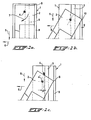
- reference 11 denotes the complete guide moving over the vertical track 3 (not shown in this drawing) provided in the rebate.
- the guide member comprises the channel section 12 engaging the track 3 and with a base 13 secured thereto, from which the pivot 14 and control pin 15 project.
- Element 16 turns about the pivot 14 and consists of an intermediate member 17 and the second pivot 18.
- Intermediate member 17 is formed with a bore 19 by means of which the intermediate member 16 fits exactly around the first pivot 14.
- the centre-line of the latter is radially spaced from the centre-line 18' of the second cylindrical pivot 18.
- the system is retained in the assembled state by means of the locking pin 19 which is fitted through the fulcrum 14 and through the opening 19a in the security plate 20 and then clinched.
- a recessed portion 21 is formed in base 13, and the intermediate member 17 fits into this portion 21, thus limiting the pivoting movement of the intermediate member, although this is not essential.
- the element to be secured in the window comprises a stepped cylindrical housing 22 having a wide portion 23 and a narrower portion 24 (see also Fig. 3d).
- Portion 24 has a stepped bore comprising a first part 25 and a second part 26; the diameter of part 25 is the same as the outside diameter of the safety plate 20 and the diameter of part 26 is the same as the outside diameter of the second pivot 18.
- Part 23 has a specially formed recess 27 which will be described in greater detail hereinafter and in which the intermediate member 17 and the control pin 15 fit.
- Housing 22 can be secured in the rebate by gluing or by means of a fixing screw 23a passing through a suitable bore.
- recess 27 is shown in Fig. 3b, having an edge boundary 28 one end of which terminates in the hollow 29 and the other end in the semi-circular boundary 30.
- the coupling member described above operates as follows:
- Figs. 4a to 4d relate to a second embodiment.
- the guide having the general reference 35 consists of a, for example, channel section 36 fitting around the guide track 3 and continuing in a base 37 from which the pivot 38 and the two control pins 39 and 40 project. These cooperate with the element 41 secured in the window and made, for-exomple, from plastics by injection moulding.
- Element 41 consists of a cylindrical fixing portion 42 fitting in the window and secured by means of the screw 43, and the guide portion 44 projecting therefrom.
- the latter has two guide paths, a first curved path 45 terminating in the receiving cavity 46, and a second guide path consisting of a straight portion 47 and a curved portion 48 also terminating in the receiving cavity 46.
- a slot 49 is formed in the middle and the pivot 38 fits therein.
- control pin 40 When the window is in the closed condition, control pin 40 is in the cavity 46 as shown at 40a and pin 38 is on the left in the slot 49 in Fig. 4b while finally pin 39 bears against the straight guide path 47, indicated at 39a.
- pin 40 When the window is then opened and pivots in the direction of arrow 50, pin 40 initially remains in the recess 46 and pivot 38 moves to the right with respect to the slot 49 - in fact part 41 moves with respect to the pivot 38 - so that the fulcrum between the coupling member and the frame moves to the left as considered in Fig. 4b.
- control pin 40 On further movement of the window, control pin 40 is free of the recess 46 and moves over the guide path 45 while control pin 39 moves over the guide paths 47, 48 until the parts finally reach the positions 40b and 39b respectively.
- the corner of the window moves freely of the draught strip or rebate.
- Fig. 5 relates to an embodiment which has the advantage of being capable of very flat construction and in which the major parts can be fitted at the top of the window. This is important for windows with a hollow structure, e.g. constructed from hollow section members.
- the guide used has the form shown in Fig. 4d with just one control pin 53 and only the pivot 54 which fits in the top end of an arm 55 connected at fulcrum 56 to window 57. At the top this window bears a guide element 58 with a guide path 59 terminating in a receiving cavity 60 in which the control pin 53 fits.
- the wall of the cavity 60 exerts a force on the pin 53 so that the top of the window will move in the direction of the arrow 62 and the point 63 of the frame stays free of the draught strip or rebate 64.
Landscapes
- Engineering & Computer Science (AREA)
- Mechanical Engineering (AREA)
- Wing Frames And Configurations (AREA)
Applications Claiming Priority (2)
| Application Number | Priority Date | Filing Date | Title |
|---|---|---|---|
| NL8100692 | 1981-02-12 | ||
| NL8100692A NL8100692A (nl) | 1981-02-12 | 1981-02-12 | Klap-draairaam. |
Publications (1)
| Publication Number | Publication Date |
|---|---|
| EP0058454A1 true EP0058454A1 (fr) | 1982-08-25 |
Family
ID=19837013
Family Applications (1)
| Application Number | Title | Priority Date | Filing Date |
|---|---|---|---|
| EP82200156A Withdrawn EP0058454A1 (fr) | 1981-02-12 | 1982-02-10 | Fenêtre à displacement rotatif et coulissant combiné |
Country Status (4)
| Country | Link |
|---|---|
| EP (1) | EP0058454A1 (fr) |
| DK (1) | DK60682A (fr) |
| FI (1) | FI820417A7 (fr) |
| NL (1) | NL8100692A (fr) |
Citations (4)
| Publication number | Priority date | Publication date | Assignee | Title |
|---|---|---|---|---|
| DE1178738B (de) * | 1958-04-21 | 1964-09-24 | Johannes Schmid Fa | Lager fuer um eine mittlere waagerechte Achse um 180íÒ schwingbare Fensterfluegel |
| EP0001487A1 (fr) * | 1977-09-30 | 1979-04-18 | Interlock Industries Limited | Entrebâilleur de fenêtre pour le montage réglable d'un châssis de fenêtre dans un dormant de fenêtre |
| GB2022669A (en) * | 1978-05-16 | 1979-12-19 | Code Designs | Compound motion windows |
| GB2025499A (en) * | 1978-07-03 | 1980-01-23 | Strand T | Mountings for reversible windows |
-
1981
- 1981-02-12 NL NL8100692A patent/NL8100692A/nl not_active Application Discontinuation
-
1982
- 1982-02-10 EP EP82200156A patent/EP0058454A1/fr not_active Withdrawn
- 1982-02-10 FI FI820417A patent/FI820417A7/fi not_active Application Discontinuation
- 1982-02-11 DK DK60682A patent/DK60682A/da not_active Application Discontinuation
Patent Citations (4)
| Publication number | Priority date | Publication date | Assignee | Title |
|---|---|---|---|---|
| DE1178738B (de) * | 1958-04-21 | 1964-09-24 | Johannes Schmid Fa | Lager fuer um eine mittlere waagerechte Achse um 180íÒ schwingbare Fensterfluegel |
| EP0001487A1 (fr) * | 1977-09-30 | 1979-04-18 | Interlock Industries Limited | Entrebâilleur de fenêtre pour le montage réglable d'un châssis de fenêtre dans un dormant de fenêtre |
| GB2022669A (en) * | 1978-05-16 | 1979-12-19 | Code Designs | Compound motion windows |
| GB2025499A (en) * | 1978-07-03 | 1980-01-23 | Strand T | Mountings for reversible windows |
Also Published As
| Publication number | Publication date |
|---|---|
| DK60682A (da) | 1982-08-13 |
| FI820417L (fi) | 1982-08-13 |
| NL8100692A (nl) | 1982-09-01 |
| FI820417A7 (fi) | 1982-08-13 |
Similar Documents
| Publication | Publication Date | Title |
|---|---|---|
| US4901475A (en) | Externally mounted latch for slidable sash window | |
| US5575116A (en) | Window vent stop | |
| US4616443A (en) | Reversible window structure | |
| US4479330A (en) | Mechanically controlled sealing rail for door leaf | |
| RU109189U1 (ru) | Двухстворчатое окно с оконными створками с боковой навеской и с нижней навеской, конструкция и регулирующее устройство окна | |
| EP4357569A1 (fr) | Ensemble fenêtre/porte ayant une fonction de ventilation et une fonction d'étanchéité horizontale | |
| US20050062292A1 (en) | Door pull having an opening assistance mechanism and sash window | |
| US5189837A (en) | Single sliding sash | |
| KR101202093B1 (ko) | 수평 밀착 창호의 잠금모듈 | |
| EP0058454A1 (fr) | Fenêtre à displacement rotatif et coulissant combiné | |
| GB2263128A (en) | Door and window securing devices | |
| US3444648A (en) | Building structure | |
| GB2239284A (en) | Slide and plug door or window | |
| US6065248A (en) | Cremorne lock mounting device for window | |
| US5542215A (en) | Sash supporting structure of hinged swinging window | |
| JPH10220124A (ja) | ドアボトムのシール装置 | |
| CN218092682U (zh) | 便于开关的淋浴房转动门 | |
| US2844850A (en) | Awning window structure and lock therefor | |
| JPS6141905Y2 (fr) | ||
| KR200245947Y1 (ko) | 미닫이 및 여닫이 겸용 창문 | |
| CN216893923U (zh) | 一种窗体用铰链 | |
| JPS6240041Y2 (fr) | ||
| KR102723749B1 (ko) | 회전축 방식 여닫이도어의 힌지장치 | |
| CN112443255B (zh) | 换气装置 | |
| KR101946902B1 (ko) | 미서기 창호 밀폐장치 |
Legal Events
| Date | Code | Title | Description |
|---|---|---|---|
| PUAI | Public reference made under article 153(3) epc to a published international application that has entered the european phase |
Free format text: ORIGINAL CODE: 0009012 |
|
| AK | Designated contracting states |
Designated state(s): BE DE FR GB NL SE |
|
| 17P | Request for examination filed |
Effective date: 19820716 |
|
| STAA | Information on the status of an ep patent application or granted ep patent |
Free format text: STATUS: THE APPLICATION HAS BEEN WITHDRAWN |
|
| 18W | Application withdrawn |
Withdrawal date: 19850604 |
|
| RIN1 | Information on inventor provided before grant (corrected) |
Inventor name: HOFSTEDE, WILLEM |