EP0058457A1 - Wärmetauscher und Rohr für den Gebrauch in einem Wärmetauscher - Google Patents
Wärmetauscher und Rohr für den Gebrauch in einem Wärmetauscher Download PDFInfo
- Publication number
- EP0058457A1 EP0058457A1 EP82200166A EP82200166A EP0058457A1 EP 0058457 A1 EP0058457 A1 EP 0058457A1 EP 82200166 A EP82200166 A EP 82200166A EP 82200166 A EP82200166 A EP 82200166A EP 0058457 A1 EP0058457 A1 EP 0058457A1
- Authority
- EP
- European Patent Office
- Prior art keywords
- pipe
- heat exchanger
- wall
- exchanger according
- channels
- Prior art date
- Legal status (The legal status is an assumption and is not a legal conclusion. Google has not performed a legal analysis and makes no representation as to the accuracy of the status listed.)
- Ceased
Links
- 239000012530 fluid Substances 0.000 claims abstract description 14
- 239000004033 plastic Substances 0.000 claims abstract description 14
- 229920003023 plastic Polymers 0.000 claims abstract description 14
- 239000000463 material Substances 0.000 claims abstract description 12
- 238000007599 discharging Methods 0.000 claims abstract description 4
- 238000005192 partition Methods 0.000 claims description 10
- 239000011810 insulating material Substances 0.000 claims description 4
- 229920001169 thermoplastic Polymers 0.000 abstract 1
- 239000004416 thermosoftening plastic Substances 0.000 abstract 1
- 238000003860 storage Methods 0.000 description 10
- 238000010438 heat treatment Methods 0.000 description 4
- 238000007789 sealing Methods 0.000 description 3
- 239000011248 coating agent Substances 0.000 description 2
- 238000000576 coating method Methods 0.000 description 2
- 239000006260 foam Substances 0.000 description 2
- 239000011888 foil Substances 0.000 description 2
- 210000002445 nipple Anatomy 0.000 description 2
- 239000008399 tap water Substances 0.000 description 2
- 235000020679 tap water Nutrition 0.000 description 2
- XLYOFNOQVPJJNP-UHFFFAOYSA-N water Substances O XLYOFNOQVPJJNP-UHFFFAOYSA-N 0.000 description 2
- 238000004873 anchoring Methods 0.000 description 1
- 238000005352 clarification Methods 0.000 description 1
- 238000010276 construction Methods 0.000 description 1
- 230000001419 dependent effect Effects 0.000 description 1
- 230000009977 dual effect Effects 0.000 description 1
- 238000005187 foaming Methods 0.000 description 1
- 238000005338 heat storage Methods 0.000 description 1
- 230000037431 insertion Effects 0.000 description 1
- 238000003780 insertion Methods 0.000 description 1
- 238000005304 joining Methods 0.000 description 1
- 239000007788 liquid Substances 0.000 description 1
- 239000000696 magnetic material Substances 0.000 description 1
- 238000004519 manufacturing process Methods 0.000 description 1
- 239000002245 particle Substances 0.000 description 1
- 239000004800 polyvinyl chloride Substances 0.000 description 1
- 229920000915 polyvinyl chloride Polymers 0.000 description 1
- 238000004904 shortening Methods 0.000 description 1
- 238000003466 welding Methods 0.000 description 1
Images
Classifications
-
- F—MECHANICAL ENGINEERING; LIGHTING; HEATING; WEAPONS; BLASTING
- F24—HEATING; RANGES; VENTILATING
- F24H—FLUID HEATERS, e.g. WATER OR AIR HEATERS, HAVING HEAT-GENERATING MEANS, e.g. HEAT PUMPS, IN GENERAL
- F24H1/00—Water heaters, e.g. boilers, continuous-flow heaters or water-storage heaters
- F24H1/18—Water-storage heaters
-
- F—MECHANICAL ENGINEERING; LIGHTING; HEATING; WEAPONS; BLASTING
- F28—HEAT EXCHANGE IN GENERAL
- F28D—HEAT-EXCHANGE APPARATUS, NOT PROVIDED FOR IN ANOTHER SUBCLASS, IN WHICH THE HEAT-EXCHANGE MEDIA DO NOT COME INTO DIRECT CONTACT
- F28D1/00—Heat-exchange apparatus having stationary conduit assemblies for one heat-exchange medium only, the media being in contact with different sides of the conduit wall, in which the other heat-exchange medium is a large body of fluid, e.g. domestic or motor car radiators
- F28D1/06—Heat-exchange apparatus having stationary conduit assemblies for one heat-exchange medium only, the media being in contact with different sides of the conduit wall, in which the other heat-exchange medium is a large body of fluid, e.g. domestic or motor car radiators with the heat-exchange conduits forming part of, or being attached to, the tank containing the body of fluid
-
- F—MECHANICAL ENGINEERING; LIGHTING; HEATING; WEAPONS; BLASTING
- F28—HEAT EXCHANGE IN GENERAL
- F28D—HEAT-EXCHANGE APPARATUS, NOT PROVIDED FOR IN ANOTHER SUBCLASS, IN WHICH THE HEAT-EXCHANGE MEDIA DO NOT COME INTO DIRECT CONTACT
- F28D20/00—Heat storage plants or apparatus in general; Regenerative heat-exchange apparatus not covered by groups F28D17/00 or F28D19/00
- F28D20/0034—Heat storage plants or apparatus in general; Regenerative heat-exchange apparatus not covered by groups F28D17/00 or F28D19/00 using liquid heat storage material
-
- Y—GENERAL TAGGING OF NEW TECHNOLOGICAL DEVELOPMENTS; GENERAL TAGGING OF CROSS-SECTIONAL TECHNOLOGIES SPANNING OVER SEVERAL SECTIONS OF THE IPC; TECHNICAL SUBJECTS COVERED BY FORMER USPC CROSS-REFERENCE ART COLLECTIONS [XRACs] AND DIGESTS
- Y02—TECHNOLOGIES OR APPLICATIONS FOR MITIGATION OR ADAPTATION AGAINST CLIMATE CHANGE
- Y02E—REDUCTION OF GREENHOUSE GAS [GHG] EMISSIONS, RELATED TO ENERGY GENERATION, TRANSMISSION OR DISTRIBUTION
- Y02E60/00—Enabling technologies; Technologies with a potential or indirect contribution to GHG emissions mitigation
- Y02E60/14—Thermal energy storage
Definitions
- the invention relates to a heat exchanger comprising a vessel for the receipt of a first fluid and at least one pipe system through which a second fluid can flow, cooperating with said vessel, the respective ends of said pipes opening into a space bridging each end.
- Heat exchangers of this type are generally known and are used for various purposes.
- the invention aims to provide a heat exchanger, more particularly a hot water storage vessel comprising an integrated exchanger, which can be obtained in a simple and cheap manner.
- Said partition constitutes the wall of a pipe, channels provided in said wall discharging into a space of a cap fastened upon an end of the pipe.
- the pipe comprising channels in its wall forms part of the wall of the vessel.
- a pipe according to the invention for use in a heat exchanger as described above, which pipe is a plastics pipe the wall of which comprises channels running parallel to the centre line of said pipe.
- the vessel is formed by the pipe the wall of which comprises channels and caps provided at both ends of the pipe and bounding the internal space of the latter, a large volume can be used for the one fluid and a small volume for the other fluid.
- Each cap is preferably composed of two scales, each of said scale comprising an axially directed circumferential flange, the circumferential flange of one scale adjoining the inner circumference of the pipe, the circumferential flange of the other scale adjoining the outer circumference of the pipe.
- both scales to be provided with a passage opening into which fits a connecting stub for a pipe conduit for interconnecting the two scales, the scale comprising the flange ad. joining the outer circumference of the pipe being provided with a second passage opening for the receipt of a connecting stub for a pipe conduit being connected to the space between the two scales.
- the total storage volume may be surrounded by heat transferring liquid flowing through the channels in the pipe wall.
- the internal and external casings around the heat transferring fluid are adapted to one another in order to obtain an increased resistance against internal overpressure of the storage value at a use of material which is as low as possible.
- a heat exchanger according to the present invention can be simply obtained by shortening a pipe comprising channels, the length of said heat exchanger and consequently, the storage volume may be variable and adapted to each desired constructional size. Said length may be much greater than the diameter of the vessel, so that at constructional sites the heat exchanger may e.g. be positioned below a roof boarding, in a creeping space, or the like.
- the heat exchanger may entirely consist of plastics, such as polyvinylchloride so that the same is entirely corrosion- proof.
- simple sealing scales can be used having an extensive adhering surface, due to presence of the circumferential flanges.
- a heat exchanger according to the invention used-as a storage vessel comprising an integrated exchanger lends itself very well for use as a solar boiler, wherein the collector fluid flows through the channels in the p# wall.
- the storage volume for tap- water or for a heating system being formed by the internal space of the pipe.
- the heat exchanger according to the invention can also be used for a heating vessel/boiler/combination, wherein the central heating fluid may be conveyed through the channels in the pipe wall by means of preferential circuiting.
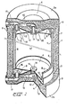
- the heat exchanger consists of a housing provided with a wall 1 consisting of a plastics pipe, a foil or a coating. Both ends of the so formed tubular casing are closed by end caps 2a, 2b respectively, also consisting of a foil or coating or of an impact resistant plastic. Said end caps are provided with circumferential flanges 3 which may project beyond the tubular casing or pipe 1.
- the caps 2a and 2b preferably comprise a central deflected region 4 in order to install the housing in a stable manner.
- the heat exchanger proper is accommodated within the housing, said heat exchanger being formed by a tubular side wall 5 comprising trend caps generally denoted by reference numeral 6.
- the space between the heat exchanger and the pipe forming the tubular casing is provided with an insulating material.
- said insulating material consists of foam
- a simple foaming up of this material in the respective space may provide an appropriate anchoring of the heat exchanger in the housing as in this manner a strong sandwhich construction is obtained.
- the foam has been denoted in the drawing by reference numeral 7.
- the heat exchanger further comprises a vessel bound by the tubular side wall 5 for the receipt of a first fluid, while at least one pipe system through which a second fluid can flow, cooperates with said vessel, the respective ends of said pipes opening into a space which bridges each end.
- the pipe system consists of a partition provided with longitudinally extending . channels 8, said partition consisting of one single integral piece of material. However, this is not imperative as the partition with channels may also be formed from separate parts.
- Said partition is therefore formed by the tubular wall 5 of the heat exchanger comprising the channels 8 which discharge into a space 9 of a cap 6 fastened upon one end of the pipe.
- Each cap 6 is composed of two scales 12, 13 respectively, each of said scales comprising an axially directed circumferential flange 10., 11 respectively, the circumferential flange 10 of one scale 12 adjoining the inner circumference of the pipe formed by the wall 5, while the circumferential flange 11 of the other scale 13 adjoins the outer circumference of said pipe.
- Both scales 12 and 13 are provided with a passage opening into which fits a connecting stub 14 for a pipe conduit 15 and for interconnecting the two scales 12 and 13.
- the scale 13 comprising the flange 11 adjoining the outer circumference of the pipe, is provided with a second passage opening for the receipt of a connecting stub 16 for a pipe conduit 17 being connected to the space 9 between the two scales 12 and 13.
- the scale 13 comprising the circumferential flange 11 which adjoins the outer circumference of the pipe has a central deflection towards the outer scale 12 and adjoins the latter, the two scales' 12 and 13 being connected to one another, by means of the connecting stub 14 for the pipe conduit 15 through the passage openings -co-iinciding with each other.
- the connecting stub 14 comprises a head 19 below which a sealing ring 20 is provided, while a nut or snapping ring 21 around the connecting stub 14 is pressed against scale 13 by the additional intermediary of a sealing ring 22.
- the pipe conduits 15 and 17 which are also embedded in the insulating material 7, run into the circumferential flange 10 and are there provided with a connecting nipple for an ambient conduit, connecting nipple 23 of conduit 17, as illustrated in the drawing.
- Said conduit 17 may, for instance, be connected to a circuit of a central heating system or a solar collector, conduit 15 being connected to a tap water conduit.
- a reverse connection may obviously also be effected, dependent on the supplied or consumed quantity of heat.
- a normal commercial plastics pipe the wall of which comprises channels 8, can be used for the partition constituted by the tubular wall 5.
- Said commercial pipe need only be shortened to a given length in dependance of the required capacity, in which case the length of pipe 1 can also be shortened, whereas the remaining equipment will always stay the same.
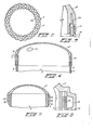
- the tubular wall 5 can have a corrugated surface.
- the thickness of the material has been much enlarged with regard to the diameter of the tubular wall.
- the inner surface 24 is corrugated.
- a filter can be used in the connection to the caps as will be described later on.
- Fig. 3 shows the insertion of the tubular wall 5 of fig. 1 in an annular channel 25 of a single end cap 6a made of plastics material.
- annular channel filling material 27 has been inserted at both sides of the tubular wall 5.
- the channels 8 open into the annular channel 25 on to which a connecting stub 16 can be arranged (not shown in this figure).
- a connecting stub 14 can be arranged at any desired place on the end cap.
- the end cap 6a can be fastened to the end of the tubular wall 5 in any suitable manner preferably by spinwelding.
- the md cap 6a shown in fig. 5 is also made as a single piece from plastics material,
- the end cap..6b is only provided with an external axial flange 28, which can rest against the outer circumference of the tubular wall 5.
- the flange 28 has been provided with a widened part forming an annular channel 29 between the tubular wall 5 and the flange 28.
- Openings 30 are provided in the outer surface of the tubular wall 5 in the area of the annular channel 29, forming a connection between this annular channel and the channels 8.
- the openings 30 are made in the form of circumferential cuts into the outer surface of the tubular wall 5, as illustrated in the axial section of fig. 6 on an enlarged scale.
- the plastics material from which the caps 6, 6a and 6b are made can be provided with particles of magnetic material owing to which the caps can be fastened to the tubular wall 5 by means of electro welding.
- Connecting stubs 14 and 16 can be also arranged in the cap 6b.
Landscapes
- Engineering & Computer Science (AREA)
- Physics & Mathematics (AREA)
- Thermal Sciences (AREA)
- Mechanical Engineering (AREA)
- General Engineering & Computer Science (AREA)
- Chemical & Material Sciences (AREA)
- Combustion & Propulsion (AREA)
- Heat-Exchange Devices With Radiators And Conduit Assemblies (AREA)
Applications Claiming Priority (2)
| Application Number | Priority Date | Filing Date | Title |
|---|---|---|---|
| NL8100725 | 1981-02-13 | ||
| NL8100725A NL8100725A (nl) | 1981-02-13 | 1981-02-13 | Warmtewisselaar en buis te gebruiken voor een warmtewisselaar. |
Publications (1)
| Publication Number | Publication Date |
|---|---|
| EP0058457A1 true EP0058457A1 (de) | 1982-08-25 |
Family
ID=19837025
Family Applications (1)
| Application Number | Title | Priority Date | Filing Date |
|---|---|---|---|
| EP82200166A Ceased EP0058457A1 (de) | 1981-02-13 | 1982-02-11 | Wärmetauscher und Rohr für den Gebrauch in einem Wärmetauscher |
Country Status (3)
| Country | Link |
|---|---|
| EP (1) | EP0058457A1 (de) |
| DK (1) | DK61882A (de) |
| NL (1) | NL8100725A (de) |
Cited By (1)
| Publication number | Priority date | Publication date | Assignee | Title |
|---|---|---|---|---|
| GB2267747A (en) * | 1992-05-21 | 1993-12-15 | James Denis Kay | Corrugated toroidal vessel for cooling foodstuffs |
Citations (5)
| Publication number | Priority date | Publication date | Assignee | Title |
|---|---|---|---|---|
| DE872211C (de) * | 1948-03-12 | 1953-03-30 | Paul Dipl-Ing Delhougne | Behaelter |
| GB1175754A (en) * | 1967-02-15 | 1969-12-23 | Gessner Kg E | Container for Liquids to be Heated or to be Cooled |
| US3578074A (en) * | 1968-03-14 | 1971-05-11 | Strebelwerk Ag | Warm water producer |
| BE823328A (fr) * | 1974-12-13 | 1975-04-01 | Preparateur accumulateur d'eau chaude et son procede de fabrication. | |
| US4213498A (en) * | 1978-11-15 | 1980-07-22 | American Hcp | Low-cost flexible plastic heat exchanger |
-
1981
- 1981-02-13 NL NL8100725A patent/NL8100725A/nl not_active Application Discontinuation
-
1982
- 1982-02-11 EP EP82200166A patent/EP0058457A1/de not_active Ceased
- 1982-02-12 DK DK61882A patent/DK61882A/da unknown
Patent Citations (5)
| Publication number | Priority date | Publication date | Assignee | Title |
|---|---|---|---|---|
| DE872211C (de) * | 1948-03-12 | 1953-03-30 | Paul Dipl-Ing Delhougne | Behaelter |
| GB1175754A (en) * | 1967-02-15 | 1969-12-23 | Gessner Kg E | Container for Liquids to be Heated or to be Cooled |
| US3578074A (en) * | 1968-03-14 | 1971-05-11 | Strebelwerk Ag | Warm water producer |
| BE823328A (fr) * | 1974-12-13 | 1975-04-01 | Preparateur accumulateur d'eau chaude et son procede de fabrication. | |
| US4213498A (en) * | 1978-11-15 | 1980-07-22 | American Hcp | Low-cost flexible plastic heat exchanger |
Cited By (2)
| Publication number | Priority date | Publication date | Assignee | Title |
|---|---|---|---|---|
| GB2267747A (en) * | 1992-05-21 | 1993-12-15 | James Denis Kay | Corrugated toroidal vessel for cooling foodstuffs |
| GB2267747B (en) * | 1992-05-21 | 1996-01-03 | James Denis Kay | A cooling vessel for rapid cooling of heated foodstuffs |
Also Published As
| Publication number | Publication date |
|---|---|
| DK61882A (da) | 1982-08-14 |
| NL8100725A (nl) | 1982-09-01 |
Similar Documents
| Publication | Publication Date | Title |
|---|---|---|
| CA1141747A (en) | Heat exchanger interplate fitting | |
| US4832119A (en) | Multi-tube heat exchanger and connectors therefor | |
| EP0005414A1 (de) | Flüssigkeitheizvorrichtung für Waschanlagen | |
| EP0610897A1 (de) | Wärmeaustausch-Vorrichtung | |
| US4779652A (en) | Unitary double wall piping system | |
| EP3715763B1 (de) | Wärmeaustauschvorrichtung | |
| US4492093A (en) | Heat exchanger system | |
| US4416222A (en) | Hot water heater circuitry | |
| US4286653A (en) | Coaxial tube in tube heat exchanger with inner tube support | |
| EP0097431A2 (de) | Wärmetauscher | |
| IE47496B1 (en) | A plastics well pipe | |
| US4646823A (en) | Pipe for utility or service systems | |
| FI68462B (fi) | Radiator | |
| KR850004799A (ko) | 내부식성 증기 발생기 | |
| CN118912587B (zh) | 一种管路集成模块、室外机及暖通设备 | |
| GB2120341A (en) | A deformable tubular connector | |
| CA2132603A1 (en) | Heat Trap for Use with Hot Water Heaters and Storage Systems | |
| DE19633236B4 (de) | Warmwasser-Speicher und Ausdehnungsgefäß für eine Heizungsanlage | |
| CN220229548U (zh) | 一种即热发热管 | |
| CN101460786B (zh) | 水绝缘器和使用该水绝缘器的电热水器 | |
| GB2083604A (en) | Heat exchanger | |
| CN114264091A (zh) | 分流器及空调器 | |
| GB2116688A (en) | Heat exchangers | |
| KR102772544B1 (ko) | 연결 및 분리가 용이한 난형관 | |
| US4510891A (en) | Liquid boiler, particularly utility-water boiler |
Legal Events
| Date | Code | Title | Description |
|---|---|---|---|
| PUAI | Public reference made under article 153(3) epc to a published international application that has entered the european phase |
Free format text: ORIGINAL CODE: 0009012 |
|
| AK | Designated contracting states |
Designated state(s): AT BE CH DE FR GB IT LU NL SE |
|
| 17P | Request for examination filed |
Effective date: 19820809 |
|
| STAA | Information on the status of an ep patent application or granted ep patent |
Free format text: STATUS: THE APPLICATION HAS BEEN REFUSED |
|
| 18R | Application refused |
Effective date: 19850126 |
|
| RIN1 | Information on inventor provided before grant (corrected) |
Inventor name: RENSINK, HERM EGBERT Inventor name: BONTJE, THEODORUS PETRUS MARIA Inventor name: LODDER, BERNHARD |