EP0058574B1 - Verfahren und Vorrichtung zur Wiederherstellung der Lichtübertragungseigenschaften eines bildübertragenden optischen Faserbündels zur Verwendung in einem Faserendoskop - Google Patents
Verfahren und Vorrichtung zur Wiederherstellung der Lichtübertragungseigenschaften eines bildübertragenden optischen Faserbündels zur Verwendung in einem Faserendoskop Download PDFInfo
- Publication number
- EP0058574B1 EP0058574B1 EP82300813A EP82300813A EP0058574B1 EP 0058574 B1 EP0058574 B1 EP 0058574B1 EP 82300813 A EP82300813 A EP 82300813A EP 82300813 A EP82300813 A EP 82300813A EP 0058574 B1 EP0058574 B1 EP 0058574B1
- Authority
- EP
- European Patent Office
- Prior art keywords
- fiber bundle
- bundle
- visible light
- light
- radiation
- Prior art date
- Legal status (The legal status is an assumption and is not a legal conclusion. Google has not performed a legal analysis and makes no representation as to the accuracy of the status listed.)
- Expired
Links
- 238000002834 transmittance Methods 0.000 title claims description 64
- 239000013307 optical fiber Substances 0.000 title claims description 26
- 238000000034 method Methods 0.000 title claims description 11
- 230000005855 radiation Effects 0.000 claims description 53
- 239000000835 fiber Substances 0.000 claims description 52
- 229910052724 xenon Inorganic materials 0.000 claims description 9
- FHNFHKCVQCLJFQ-UHFFFAOYSA-N xenon atom Chemical compound [Xe] FHNFHKCVQCLJFQ-UHFFFAOYSA-N 0.000 claims description 9
- 229910052736 halogen Inorganic materials 0.000 claims description 3
- 150000002367 halogens Chemical class 0.000 claims description 3
- 238000011084 recovery Methods 0.000 description 28
- 230000003595 spectral effect Effects 0.000 description 18
- 238000005286 illumination Methods 0.000 description 7
- 239000011521 glass Substances 0.000 description 6
- 230000003287 optical effect Effects 0.000 description 5
- 238000010521 absorption reaction Methods 0.000 description 4
- 229910000420 cerium oxide Inorganic materials 0.000 description 3
- 239000003822 epoxy resin Substances 0.000 description 3
- 239000003365 glass fiber Substances 0.000 description 3
- 229910052751 metal Inorganic materials 0.000 description 3
- 239000002184 metal Substances 0.000 description 3
- 239000005304 optical glass Substances 0.000 description 3
- BMMGVYCKOGBVEV-UHFFFAOYSA-N oxo(oxoceriooxy)cerium Chemical compound [Ce]=O.O=[Ce]=O BMMGVYCKOGBVEV-UHFFFAOYSA-N 0.000 description 3
- 229920000647 polyepoxide Polymers 0.000 description 3
- 239000000853 adhesive Substances 0.000 description 2
- 230000001070 adhesive effect Effects 0.000 description 2
- 230000007423 decrease Effects 0.000 description 2
- 210000001198 duodenum Anatomy 0.000 description 2
- 230000000694 effects Effects 0.000 description 2
- 238000007459 endoscopic retrograde cholangiopancreatography Methods 0.000 description 2
- 239000000463 material Substances 0.000 description 2
- 230000001681 protective effect Effects 0.000 description 2
- 229910052684 Cerium Inorganic materials 0.000 description 1
- 210000000013 bile duct Anatomy 0.000 description 1
- 230000015556 catabolic process Effects 0.000 description 1
- GWXLDORMOJMVQZ-UHFFFAOYSA-N cerium Chemical compound [Ce] GWXLDORMOJMVQZ-UHFFFAOYSA-N 0.000 description 1
- 238000005253 cladding Methods 0.000 description 1
- 210000001072 colon Anatomy 0.000 description 1
- 230000000295 complement effect Effects 0.000 description 1
- 239000002872 contrast media Substances 0.000 description 1
- 239000013078 crystal Substances 0.000 description 1
- 230000001186 cumulative effect Effects 0.000 description 1
- 238000006731 degradation reaction Methods 0.000 description 1
- 238000002845 discoloration Methods 0.000 description 1
- 238000002474 experimental method Methods 0.000 description 1
- 238000005562 fading Methods 0.000 description 1
- 238000002594 fluoroscopy Methods 0.000 description 1
- LNEPOXFFQSENCJ-UHFFFAOYSA-N haloperidol Chemical compound C1CC(O)(C=2C=CC(Cl)=CC=2)CCN1CCCC(=O)C1=CC=C(F)C=C1 LNEPOXFFQSENCJ-UHFFFAOYSA-N 0.000 description 1
- 238000010438 heat treatment Methods 0.000 description 1
- 230000005865 ionizing radiation Effects 0.000 description 1
- 230000031700 light absorption Effects 0.000 description 1
- 238000005259 measurement Methods 0.000 description 1
- 239000000203 mixture Substances 0.000 description 1
- 238000012544 monitoring process Methods 0.000 description 1
- 230000007935 neutral effect Effects 0.000 description 1
- 238000009994 optical bleaching Methods 0.000 description 1
- 210000000277 pancreatic duct Anatomy 0.000 description 1
- 230000002441 reversible effect Effects 0.000 description 1
- 210000002784 stomach Anatomy 0.000 description 1
- 230000002194 synthesizing effect Effects 0.000 description 1
- 230000001225 therapeutic effect Effects 0.000 description 1
- 238000004383 yellowing Methods 0.000 description 1
Images




Classifications
-
- G—PHYSICS
- G02—OPTICS
- G02B—OPTICAL ELEMENTS, SYSTEMS OR APPARATUS
- G02B23/00—Telescopes, e.g. binoculars; Periscopes; Instruments for viewing the inside of hollow bodies; Viewfinders; Optical aiming or sighting devices
- G02B23/24—Instruments or systems for viewing the inside of hollow bodies, e.g. fibrescopes
- G02B23/26—Instruments or systems for viewing the inside of hollow bodies, e.g. fibrescopes using light guides
-
- A—HUMAN NECESSITIES
- A61—MEDICAL OR VETERINARY SCIENCE; HYGIENE
- A61B—DIAGNOSIS; SURGERY; IDENTIFICATION
- A61B1/00—Instruments for performing medical examinations of the interior of cavities or tubes of the body by visual or photographical inspection, e.g. endoscopes; Illuminating arrangements therefor
- A61B1/00163—Optical arrangements
- A61B1/00165—Optical arrangements with light-conductive means, e.g. fibre optics
-
- G—PHYSICS
- G02—OPTICS
- G02B—OPTICAL ELEMENTS, SYSTEMS OR APPARATUS
- G02B6/00—Light guides; Structural details of arrangements comprising light guides and other optical elements, e.g. couplings
- G02B6/24—Coupling light guides
- G02B6/42—Coupling light guides with opto-electronic elements
- G02B6/4298—Coupling light guides with opto-electronic elements coupling with non-coherent light sources and/or radiation detectors, e.g. lamps, incandescent bulbs, scintillation chambers
Definitions
- the present invention relates to a method of and apparatus for restoring the light transmittance of an image transmitting optical fiber bundle which has been reduced by X-ray or y-ray irradiation and for thus making it acceptable for performing observation or examination.
- Fiberoptic endoscopes are widely used for observing or examining inaccessible body cavities which are impossible to directly observe or examine from the outside, and are generally divided into two categories, i.e., medical and industrial ones.
- Fiberoptic endoscopes for medical use are used to observe or examine cavities of a human body such as the stomach, the duodenum, the colon, and the like, and the others are used to observe or examine the internal parts of machinery such as engines, nuclear reactors and the like.
- These fiberoptic endoscopes comprise optical fiber bundles, one for transmitting an image of the internal parts to be observed or examined and the other for transmitting illumination light from the outside.
- Each of said optical fiber bundles comprises an extremely large number of optical fibers with their opposed end portions glued and the major portions between the ends separated so as to be flexible and thus insertable along a tortuous passage of a body.
- a certain fiberoptic endoscope for medical use for instance a duodenum endoscope, can be utilized for the purpose of Endoscopic retrograde cholangiopan- creatography (ERCP) examinations wherein a contrast medium is, for a fluoroscopic observation, injected into the pancreatic and bile ducts through a tube which is inserted in a therapeutic instrument guide channel of a fiberoptic endoscope.
- ERCP Endoscopic retrograde cholangiopan- creatography
- the irradiation-induced coloration of glass unavoidably occurs in an image transmitting optical fiber bundle having thousands to tens of thousands of glass fibers each of which is composed of a fiber core and fiber cladding and has a diameter of microns in order upon being exposed to irradiation. Therefore, an optical fiber bundle used in a fiberoptic endoscope has many opportunities to be frequently exposed to irradiation and thus increases in absorption of light having wavelengths 400 to 550 nm so as to be colored yellowish brown. The yellowish brown coloration appears on a fiber bundle within a protective tube after irradiation of some Roentgens (R) and develops as the exposure does to the fiber bundle increases.
- Roentgens R
- a fiberoptic endoscope having an image transmitting fiber bundle with irradiation-induced coloration unacceptable for observing or examining an image therethrough is returned to a manufacturer to replace the image transmitting fiber bundle.
- An image transmitting fiber bundle is very expensive, further the replacement of which is extremely complex in operation and hence very costly.
- the present invention seeks to provide an effective means of restoring the light transmittance of the image transmitting fibre optic bundle of a fibre optic endoscope.
- the method according to the present invention is characterised in that the light transmitting bundle being the image transmitting bundle of a fibre optic endoscope, and having an objective lens at its distal end, said image transmitting optical fiber bundle is exposed to visible light radiation by directing said visible light radiation into the bundle through the end from which said image is normally viewed.
- a second aspect of the present invention provides a fibre optic endoscope comprising an image transmitting optical fiber bundle having a light transmittance which in use is reduced by irradiation, the bundle having an end from which a transmitted image is normally viewed and an objective lens assembly at its distal end, characterised by the provision, in operative combination with the endoscope, of apparatus for restoring the light transmittance of the bundle, the apparatus comprising:- .
- Figure 1 the apparatus illustrated in Figure 1 was used to carry out experimental measurements of correlations between wavelength and irradiation in fading of color of an image transmitting fiber bundle of a fiberoptic endoscope induced by irradiation.
- light emitted backward from a xenon lamp 1 is reflected by a parabolic mirror 2 to be directed forward and the remainder which is emitted forward from a xenon lamp 1 falls directly upon a heat absorbing filter 3.
- Light passed through the heat absorbing filter 3 can fall upon a - condenser tens or condenser lens assembly 6 through a stop 4 with a aperture of 28 mm and an interference filter 5.
- the condenser lens assembly 6 serves to use light emitted from the xenon lamp 1 effectively and to converge them onto an end surface 8 of an optical filter bundle 7 comprising an extremely large number of otical fibers each of diameter about 10 to 20 um.
- the optical fiber bundle 7 to be measured is identical with one used for an image transmitting fiber bundle of fiberoptic endoscope in every respect. That is to say, both ends of the optical fiber bundle 7 are in the form of a square with one side of 2 mm and have an overall length of 1250 mm.
- optical fibers of the fiber bundle 7 are rigidly maintained by an adhesive such as an epoxy resin so as to be exactly held in the same spatial relationship, and they are free along their path between the end faces so as to be flexible or freely movable. Furthermore the fiber bundle 7 is covered by a rubber tube for protection.
- the fiber bundle 7 has been exposed, from the exit end to about 300 mm away therefrom, to 90R irradiation by a X-ray tube using 85 KVp and 300 mA, and thus colored yellow.
- Figure 2 shows the radiation density distribution of the xenon lamp.
- the xenon lamp 1 has a density characteristic with flatness in the range of visible wavelength 380 to 780 nm.
- Figure 3 shows the spectral transmittance factors of a heat absorbing filter and an interference filter.
- the heat absorbing filter 3 which has a spectral transmittance factor represented by curve 11 can remove heat rays from radiation emitted from the xenon lamp 1.
- the heat absorbing filter 3 serves to prevent the epoxy resins used as adhesive for rigidly holding the fibers at their end portions from blackening which is caused upon heating of the epoxy resin higher than its heat-resisting temperature of about 80 to 100 degrees C.
- Figure 4 shows differences in the spectral transmittance factor of the fiber bundle 7 experimentally obtained after visible light irradiation at various periods of time through the interference filter having its central wavelength at 404 nm in the apparatus shown in Figure 1.
- the curve 15 in Figure 4 represents the spectral transmittance factor of the fiber bundle 7 before X-ray irradiation, and the curve 16 represents it after the fiber bundle 7 in the region from the light exit end 10 to about 300 mm away therefrom irradiated by X-rays of 90R and colored yellow.
- the fiber bundle 7 having its spectral transmittance factor lowered to that shown by the curve 16 was, at its end 8, radiated by visible light through the interference filter having its central wavelength at 404 for a quarter of an hour, for a half of an hour, for-an hour, for two hours and for four hours.
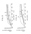
- Figure 5 shows differences in spectral transmittance factor of the fiber bundle 7 experimentally obtained after visible light radiation for various periods of time through the interference filter having its central wavelength at 470 nm.
- the curves 22 to 25 represent the spectral transmittance factors of the fiber bundle 7 positively observed after visible light radiation of a quarter of an hour, for a half of an hour, for an hour and two hours, respectively.
- the curves 15 and 16 represent the spectral transmittance factor of the fiber bundle before and after X-ray irradiation, respecectively, in the same manner as shown by the curves in Figure 4.
- Figure 6 shows differences in spectral transmittance factors of the fiber bundle 7 experimentally obtained after visible light radiation through the interference filter having its central wavelength at 582 nm.
- the curves 27 to 30 represent spectral transmittance factors of the fiber bundle recovered after visible light radiation for a quarter of an hour, for a half of an hour, for an hour and for two hours, respectively.
- Figure 7 shows the recovery of light transmittance of the fiber bundle 7 with time by plotting the experimental values at the wavelength of 435 nm.
- Curves 32 to 34 showing the recovery of light transmittance at the wavelength of 435 nm of the fiber bundle 7 are in the case of using the interference filters having central wavelengths at 582 nm, 470 nm and 404, respectively, and curve 35 is without any interference filter.
- the recovery of light transmittance plotted along the ordinate represents the rate of light transmittance recovery to that before X-ray irradiation.
- curve 37 represents the recovery of light transmittance of a fiber bundle after visible light radiation without any ND filter
- curve 38 represents the recovery of light transmittance of a fiber bundle after visible light radiation using a quarter of the total quantity of radiation by using a ND filter having a density of 4 (four)
- a curve 39 represents the recovery of light transmittance of a fiber bundle after visible light radiation using one sixteenth of the total quantity of radiation by using two ND filters having a density of 4 (four)
- curve 40 represents the recovery of light transmittance after radiation reduced to 1/128 of the total quantity of radiation using two ND filters having a density of 4 and a ND filter having a density of 8. It will be apparant from Figure 8thatthe larger the quantity the visible light radiation is, the higher the recovery of light transmittance is.
- Figure 9 shows relationships between the recovery of light transmittance of a fiber bundle and the quantity of visible light radiation (log. E).
- a characteristic curve 42 represents the recovery of light transmittance of a fiber bundle after visible light radiation without any filter
- the characteristic curve 43 represents the recovery of light transmittance of a fiber bundle after visible radiation reduced to one quarter of the total quantity of radiation by using a filter
- the characteristic curve 44 represents the recovery of transmittance after the radiation was reduced to one sixteenth
- the characteristic curve 45 represents the recovery of light transmittance after the radiation was reduced to 1/128th. It will be apparent from Figure 9 that the recovery of light transmittance in rate is not proportional to the quantity of visible light radiation and that the larger the quantity of visible light radiation is, the higher the recovery of light transmittance is.
- Figure 10 illustrates an embodiment of apparatus for restoring light transmittance of a fiber bundle within a fiberoptic endoscope.
- a fiberoptic endoscope 47 comprises an elongated and flexible part 48 which is insertable into an body to be examined, a remote control part 49; an ocular part 50 and an illumination light source apparatus 51 and includes an image transmitting optical fiber bundle 52 and an illumination light transmitting optical fiber bundle 53 therein.
- the elongated and flexible part 48 is, as is well known, adapted to face the top thereof towards any desired direction by operating a control knob on the remote control part 49.
- Light emitted from a light source 54 provided in the illumination light source apparatus 51 is incident into the light transmitting optical fiber bundle 53 through its incident end 55 and is emitted through the exit end 56. Illumination light can further emit through a window 57 to then illuminate the area to be examined or observed.
- Reflected light from the area is converged onto an incident end 60 of the image transmitting optical fiber bundle 52 through the window 58 and an objective assembly 59.
- the image-at exit end 61 of the image transmitting optical fiber bundle can be observed through an ocular assembly 62 after magnification.
- the actual dose received by the fiber bundle within the flexible part 48 is about 0.1 R per one examination.
- the light transmittance of the image transmitting optical fiber bundle is gradually reduced with yellowing thereof and consequently the image transmitting optical fiber bundle becomes unacceptable for use after a total dose of about 24R. Therefore it is desirable to restore the reduced light transmittance of the image transmitting optical fiber bundle after a certain cumulative dose for instance a total dose of about 1.OR by using the light transmittance restoring apparatus 64.
- the light transmittance recovering apparatus 64 which comprises a light source 66 emitting radiation containing short wavelength visible light, a reflecting mirror 67 and a heat absorbing filter 68 in casing 65 is adapted to be detachably connected to the ocular assembly part 50.
- the connecting means is comprised as a bayonet mount with which a casing 65 is provided,
- the bayonet mount has bayonet detents 69 engageable with complementary bayonet detents 70 of the ocular assembly part 50 which are provided for mounting a camera or the like thereon.
- a xenon lamp, a halogen lamp, a metal halogen lamp or the like may be employed as the light source 66.
- the illumination light source apparatus 51 can be used as a light transmittance restoring apparatus and in this case the illumination light source apparatus 51 is connected to the ocular assembly part 50, for example through a mounting means.
Landscapes
- Physics & Mathematics (AREA)
- Optics & Photonics (AREA)
- Health & Medical Sciences (AREA)
- Life Sciences & Earth Sciences (AREA)
- Surgery (AREA)
- General Physics & Mathematics (AREA)
- Heart & Thoracic Surgery (AREA)
- Molecular Biology (AREA)
- Pathology (AREA)
- Radiology & Medical Imaging (AREA)
- Biophysics (AREA)
- Engineering & Computer Science (AREA)
- Biomedical Technology (AREA)
- Astronomy & Astrophysics (AREA)
- Nuclear Medicine, Radiotherapy & Molecular Imaging (AREA)
- Animal Behavior & Ethology (AREA)
- Medical Informatics (AREA)
- General Health & Medical Sciences (AREA)
- Public Health (AREA)
- Veterinary Medicine (AREA)
- Endoscopes (AREA)
- Instruments For Viewing The Inside Of Hollow Bodies (AREA)
- Optical Fibers, Optical Fiber Cores, And Optical Fiber Bundles (AREA)
Claims (14)
Priority Applications (1)
| Application Number | Priority Date | Filing Date | Title |
|---|---|---|---|
| AT82300813T ATE17790T1 (de) | 1981-02-17 | 1982-02-17 | Verfahren und vorrichtung zur wiederherstellung der lichtuebertragungseigenschaften eines bilduebertragenden optischen faserbuendels zur verwendung in einem faserendoskop. |
Applications Claiming Priority (4)
| Application Number | Priority Date | Filing Date | Title |
|---|---|---|---|
| JP56022082A JPS57146203A (en) | 1981-02-17 | 1981-02-17 | Method and device for recovering light transmittivity of optical fiber |
| JP22082/81 | 1981-02-17 | ||
| JP57005907A JPS58123505A (ja) | 1982-01-20 | 1982-01-20 | 内視鏡の像伝達用光学繊維束の光透過率回復方法及び装置 |
| JP5907/82 | 1982-01-20 |
Publications (3)
| Publication Number | Publication Date |
|---|---|
| EP0058574A2 EP0058574A2 (de) | 1982-08-25 |
| EP0058574A3 EP0058574A3 (en) | 1982-12-01 |
| EP0058574B1 true EP0058574B1 (de) | 1986-01-29 |
Family
ID=26339933
Family Applications (1)
| Application Number | Title | Priority Date | Filing Date |
|---|---|---|---|
| EP82300813A Expired EP0058574B1 (de) | 1981-02-17 | 1982-02-17 | Verfahren und Vorrichtung zur Wiederherstellung der Lichtübertragungseigenschaften eines bildübertragenden optischen Faserbündels zur Verwendung in einem Faserendoskop |
Country Status (8)
| Country | Link |
|---|---|
| US (1) | US4523806A (de) |
| EP (1) | EP0058574B1 (de) |
| AR (1) | AR229690A1 (de) |
| AU (1) | AU541958B2 (de) |
| CA (1) | CA1192071A (de) |
| DE (1) | DE3268730D1 (de) |
| FR (1) | FR2500201A1 (de) |
| GB (1) | GB2094021B (de) |
Families Citing this family (40)
| Publication number | Priority date | Publication date | Assignee | Title |
|---|---|---|---|---|
| EP0067555A3 (de) * | 1981-05-22 | 1983-11-09 | Fuji Photo Optical Co., Ltd. | Gerät zur Wiederherstellung der Lichtdurchlässigkeit eines Endoskop-Bildleiter-Bündels |
| JPS5811036A (ja) * | 1981-07-13 | 1983-01-21 | Fuji Photo Optical Co Ltd | ガラスの光透過率の回復方法および装置 |
| JPS60218635A (ja) * | 1984-04-13 | 1985-11-01 | Canon Inc | 照明装置 |
| NL8402124A (nl) * | 1984-07-04 | 1986-02-03 | Philips Nv | Inrichting voor het belichten van een uv hardende laag op een draadvormig lichaam. |
| US4641033A (en) * | 1984-12-19 | 1987-02-03 | Fusion Systems Corporation | Apparatus and method preventing radiation induced degradation of optical elements |
| SE455968B (sv) * | 1985-03-01 | 1988-08-22 | Ericsson Telefon Ab L M | Optokabel |
| CA1292461C (en) * | 1987-02-12 | 1991-11-26 | Hiromu Terada | Endoscope |
| US4830447A (en) * | 1987-02-13 | 1989-05-16 | Fuji Photo Film Co., Ltd. | Optical wavelength conversion device |
| US5177605A (en) * | 1987-04-28 | 1993-01-05 | Olympus Optical Co., Ltd. | Optical system for endoscopes and endoscopes using same |
| US5073048A (en) * | 1987-07-06 | 1991-12-17 | Asahi Kogaku Kogyo K.K. | Optical fiber bundle |
| JPS6480374A (en) * | 1987-09-21 | 1989-03-27 | Takashi Mori | Lamp for radiating ray |
| JP2755650B2 (ja) * | 1989-02-01 | 1998-05-20 | 株式会社東芝 | 露光装置 |
| US5394499A (en) * | 1992-12-28 | 1995-02-28 | Olympus Optical Co., Ltd. | Observation system with an endoscope |
| US5513291A (en) * | 1993-10-08 | 1996-04-30 | Origin Medsystems, Inc. | Light source modifications for plastic light fibre compatibility |
| ES2127156B1 (es) * | 1997-09-05 | 1999-12-16 | Navarro Frances J E | Sistema luminoso. |
| DE19739023A1 (de) * | 1997-09-06 | 1999-03-11 | Hella Kg Hueck & Co | Reflektorleuchte |
| RU2239179C1 (ru) * | 2003-09-25 | 2004-10-27 | Войсковая часть 75360 | Рентгенооптический эндоскоп |
| RU2377544C1 (ru) * | 2008-04-11 | 2009-12-27 | Виктор Яковлевич Маклашевский | Рентгенооптический эндоскоп |
| RU2387979C2 (ru) * | 2008-06-07 | 2010-04-27 | Виктор Яковлевич Маклашевский | Рентгенооптический эндоскоп |
| RU2386955C1 (ru) * | 2008-08-04 | 2010-04-20 | Виктор Яковлевич Маклашевский | Рентгенооптический эндоскоп |
| RU2386956C1 (ru) * | 2008-08-04 | 2010-04-20 | Виктор Яковлевич Маклашевский | Рентгенооптический эндоскоп |
| RU2413205C1 (ru) * | 2009-08-04 | 2011-02-27 | Виктор Яковлевич Маклашевский | Рентгенооптический эндоскоп |
| RU2413932C1 (ru) * | 2009-08-04 | 2011-03-10 | Виктор Яковлевич Маклашевский | Рентгенооптический эндоскоп |
| RU2413206C1 (ru) * | 2009-08-04 | 2011-02-27 | Виктор Яковлевич Маклашевский | Рентгенооптический эндоскоп |
| RU2405136C1 (ru) * | 2009-08-14 | 2010-11-27 | Виктор Яковлевич Маклашевский | Рентгенооптический эндоскоп |
| RU2405135C1 (ru) * | 2009-08-14 | 2010-11-27 | Виктор Яковлевич Маклашевский | Рентгенооптический эндоскоп |
| RU2405137C1 (ru) * | 2009-08-20 | 2010-11-27 | Виктор Яковлевич Маклашевский | Рентгенооптический эндоскоп |
| RU2405138C1 (ru) * | 2009-08-20 | 2010-11-27 | Виктор Яковлевич Маклашевский | Рентгенооптический эндоскоп |
| CN102791177B (zh) * | 2010-10-12 | 2014-12-31 | 奥林巴斯医疗株式会社 | 内窥镜 |
| JP5380581B2 (ja) * | 2012-06-08 | 2014-01-08 | 株式会社フジクラ | 照明構造及び内視鏡 |
| CN106922122A (zh) * | 2014-11-18 | 2017-07-04 | 奥林巴斯株式会社 | 内窥镜用光源系统 |
| US11437774B2 (en) | 2015-08-19 | 2022-09-06 | Kyocera Sld Laser, Inc. | High-luminous flux laser-based white light source |
| WO2020129147A1 (ja) | 2018-12-18 | 2020-06-25 | オリンパス株式会社 | 内視鏡用光源装置、及びこれを有する内視鏡 |
| US11239637B2 (en) | 2018-12-21 | 2022-02-01 | Kyocera Sld Laser, Inc. | Fiber delivered laser induced white light system |
| US11421843B2 (en) | 2018-12-21 | 2022-08-23 | Kyocera Sld Laser, Inc. | Fiber-delivered laser-induced dynamic light system |
| US12152742B2 (en) | 2019-01-18 | 2024-11-26 | Kyocera Sld Laser, Inc. | Laser-based light guide-coupled wide-spectrum light system |
| US12000552B2 (en) | 2019-01-18 | 2024-06-04 | Kyocera Sld Laser, Inc. | Laser-based fiber-coupled white light system for a vehicle |
| JP3236102U (ja) * | 2019-01-18 | 2022-02-09 | キョウセラ エスエルディー レイザー,インコーポレイテッド | 照明アプリケーション用のレーザベースの導波路結合白色光システム |
| US11884202B2 (en) | 2019-01-18 | 2024-01-30 | Kyocera Sld Laser, Inc. | Laser-based fiber-coupled white light system |
| DE102019114763A1 (de) * | 2019-06-03 | 2020-12-03 | Olympus Winter & Ibe Gmbh | Endoskop mit verklebtem Lichtleiter |
Family Cites Families (6)
| Publication number | Priority date | Publication date | Assignee | Title |
|---|---|---|---|---|
| US1662150A (en) * | 1926-04-05 | 1928-03-13 | American Optical Corp | Fused-quartz transilluminator |
| US3131690A (en) * | 1962-10-22 | 1964-05-05 | American Optical Corp | Fiber optics devices |
| JPS5929681Y2 (ja) * | 1974-12-26 | 1984-08-25 | 株式会社メドス研究所 | 内視鏡における自動露出制御用測光装置 |
| US4157253A (en) * | 1978-06-23 | 1979-06-05 | Rca Corporation | Method of reducing absorption losses in fused quartz and fused silica optical fibers |
| FR2455299A1 (fr) * | 1979-04-23 | 1980-11-21 | Thomson Csf | Illuminateur a lampe a arc et dispositif optique de transfert par projection comportant un tel illuminateur |
| US4232228A (en) * | 1979-08-07 | 1980-11-04 | The United States Of America As Represented By The United States Department Of Energy | Method of lightening radiation darkened optical elements |
-
1982
- 1982-02-15 FR FR8202432A patent/FR2500201A1/fr not_active Withdrawn
- 1982-02-16 CA CA000396344A patent/CA1192071A/en not_active Expired
- 1982-02-17 AU AU80540/82A patent/AU541958B2/en not_active Ceased
- 1982-02-17 EP EP82300813A patent/EP0058574B1/de not_active Expired
- 1982-02-17 GB GB8204625A patent/GB2094021B/en not_active Expired
- 1982-02-17 DE DE8282300813T patent/DE3268730D1/de not_active Expired
- 1982-02-17 AR AR288452A patent/AR229690A1/es active
- 1982-02-17 US US06/349,619 patent/US4523806A/en not_active Expired - Fee Related
Also Published As
| Publication number | Publication date |
|---|---|
| AU541958B2 (en) | 1985-01-31 |
| DE3268730D1 (en) | 1986-03-13 |
| EP0058574A3 (en) | 1982-12-01 |
| GB2094021B (en) | 1985-07-17 |
| GB2094021A (en) | 1982-09-08 |
| AR229690A1 (es) | 1983-10-31 |
| AU8054082A (en) | 1982-08-26 |
| CA1192071A (en) | 1985-08-20 |
| EP0058574A2 (de) | 1982-08-25 |
| US4523806A (en) | 1985-06-18 |
| FR2500201A1 (fr) | 1982-08-20 |
Similar Documents
| Publication | Publication Date | Title |
|---|---|---|
| US4523806A (en) | Method and apparatus for restoring the light transmittance of an image-transmitting optical fiber bundle used in a fiber optic endoscope | |
| US4072147A (en) | Radiation endoscope | |
| US3456641A (en) | Flexible endoscope for photographing diseased parts in cancer diagnosis | |
| WO2012050116A1 (ja) | 内視鏡 | |
| Ranchoux et al. | Fibre remote optoelectronic gamma dosimetry based on optically stimulated luminescence of Al2O3: C | |
| US4776668A (en) | Image focusing ocular piece for a viewing scope including mechanism for accommodating differential expansion | |
| JP2000514697A (ja) | 混濁媒体中の対象を局所化する装置 | |
| JP7474268B2 (ja) | ファイバオプティックプレート、シンチレータパネル、放射線検出器、電子顕微鏡、x線遮蔽方法、及び、電子線遮蔽方法 | |
| JPS6262322B2 (de) | ||
| US4232228A (en) | Method of lightening radiation darkened optical elements | |
| JP2914676B2 (ja) | ファイバスコープ | |
| EP0067555A3 (de) | Gerät zur Wiederherstellung der Lichtdurchlässigkeit eines Endoskop-Bildleiter-Bündels | |
| EP0068175A1 (de) | Bildübertragendes Faserbündel | |
| EP0070193B1 (de) | Gerät zur Beseitigung von durch Bestrahlung verursachter Verminderung der Lichtdurchlässigkeit transparenten Glases | |
| JP3262149B2 (ja) | 赤外検知器およびその励起方法 | |
| Weiss | The radiation response of a Selfoc microlens | |
| JPS6119964B2 (de) | ||
| JPS6348322B2 (de) | ||
| Saito et al. | Polymer coating on infrared silver halide fiber for photodarkening protection | |
| JPS58184106A (ja) | 繊維光学系の再生方法 | |
| Siegmund | 21. UNCONVENTIONAL FIBER OPTICS | |
| Buyken et al. | Properties of UV-fibers | |
| WO1989007257A1 (en) | Fiber optic beam-imaging apparatus and method | |
| JPH0143687Y2 (de) | ||
| JPS59129805A (ja) | γ線環境内点検用映像装置 |
Legal Events
| Date | Code | Title | Description |
|---|---|---|---|
| PUAI | Public reference made under article 153(3) epc to a published international application that has entered the european phase |
Free format text: ORIGINAL CODE: 0009012 |
|
| AK | Designated contracting states |
Designated state(s): AT BE CH DE IT NL SE |
|
| PUAL | Search report despatched |
Free format text: ORIGINAL CODE: 0009013 |
|
| RHK1 | Main classification (correction) |
Ipc: G02B 5/14 |
|
| AK | Designated contracting states |
Designated state(s): AT BE CH DE IT NL SE |
|
| 17P | Request for examination filed |
Effective date: 19830307 |
|
| ITF | It: translation for a ep patent filed | ||
| GRAA | (expected) grant |
Free format text: ORIGINAL CODE: 0009210 |
|
| AK | Designated contracting states |
Designated state(s): AT BE CH DE IT LI NL SE |
|
| REF | Corresponds to: |
Ref document number: 17790 Country of ref document: AT Date of ref document: 19860215 Kind code of ref document: T |
|
| PGFP | Annual fee paid to national office [announced via postgrant information from national office to epo] |
Ref country code: AT Payment date: 19860214 Year of fee payment: 5 |
|
| PGFP | Annual fee paid to national office [announced via postgrant information from national office to epo] |
Ref country code: NL Payment date: 19860228 Year of fee payment: 5 |
|
| REF | Corresponds to: |
Ref document number: 3268730 Country of ref document: DE Date of ref document: 19860313 |
|
| PLBE | No opposition filed within time limit |
Free format text: ORIGINAL CODE: 0009261 |
|
| STAA | Information on the status of an ep patent application or granted ep patent |
Free format text: STATUS: NO OPPOSITION FILED WITHIN TIME LIMIT |
|
| 26N | No opposition filed | ||
| PG25 | Lapsed in a contracting state [announced via postgrant information from national office to epo] |
Ref country code: AT Effective date: 19870217 |
|
| PG25 | Lapsed in a contracting state [announced via postgrant information from national office to epo] |
Ref country code: SE Effective date: 19870218 |
|
| PG25 | Lapsed in a contracting state [announced via postgrant information from national office to epo] |
Ref country code: LI Effective date: 19870228 Ref country code: CH Effective date: 19870228 |
|
| BERE | Be: lapsed |
Owner name: FUJI PHOTO OPTICAL CO. LTD. Effective date: 19870228 |
|
| PG25 | Lapsed in a contracting state [announced via postgrant information from national office to epo] |
Ref country code: NL Effective date: 19870901 |
|
| NLV4 | Nl: lapsed or anulled due to non-payment of the annual fee | ||
| REG | Reference to a national code |
Ref country code: CH Ref legal event code: PL |
|
| PG25 | Lapsed in a contracting state [announced via postgrant information from national office to epo] |
Ref country code: DE Effective date: 19871103 |
|
| PG25 | Lapsed in a contracting state [announced via postgrant information from national office to epo] |
Ref country code: BE Effective date: 19890228 |
|
| EUG | Se: european patent has lapsed |
Ref document number: 82300813.1 Effective date: 19880215 |