EP0058580A1 - Elektrischer Verbinder mit einfacher Verriegelung - Google Patents
Elektrischer Verbinder mit einfacher Verriegelung Download PDFInfo
- Publication number
- EP0058580A1 EP0058580A1 EP19820400063 EP82400063A EP0058580A1 EP 0058580 A1 EP0058580 A1 EP 0058580A1 EP 19820400063 EP19820400063 EP 19820400063 EP 82400063 A EP82400063 A EP 82400063A EP 0058580 A1 EP0058580 A1 EP 0058580A1
- Authority
- EP
- European Patent Office
- Prior art keywords
- skirt
- electrical
- conductor
- connector according
- locking
- Prior art date
- Legal status (The legal status is an assumption and is not a legal conclusion. Google has not performed a legal analysis and makes no representation as to the accuracy of the status listed.)
- Granted
Links
- 239000004020 conductor Substances 0.000 claims abstract description 32
- 238000007789 sealing Methods 0.000 claims description 5
- 210000004907 gland Anatomy 0.000 claims description 4
- 230000003071 parasitic effect Effects 0.000 abstract description 4
- 244000045947 parasite Species 0.000 description 3
- 230000036039 immunity Effects 0.000 description 2
- 230000001681 protective effect Effects 0.000 description 2
- 230000002285 radioactive effect Effects 0.000 description 2
- 238000013459 approach Methods 0.000 description 1
- 239000000470 constituent Substances 0.000 description 1
- 238000005336 cracking Methods 0.000 description 1
- 238000010586 diagram Methods 0.000 description 1
- 230000000694 effects Effects 0.000 description 1
- 230000005684 electric field Effects 0.000 description 1
- 231100001261 hazardous Toxicity 0.000 description 1
- 239000012212 insulator Substances 0.000 description 1
- 239000002184 metal Substances 0.000 description 1
- 230000035515 penetration Effects 0.000 description 1
- XLYOFNOQVPJJNP-UHFFFAOYSA-N water Substances O XLYOFNOQVPJJNP-UHFFFAOYSA-N 0.000 description 1
Images

Classifications
-
- H—ELECTRICITY
- H01—ELECTRIC ELEMENTS
- H01R—ELECTRICALLY-CONDUCTIVE CONNECTIONS; STRUCTURAL ASSOCIATIONS OF A PLURALITY OF MUTUALLY-INSULATED ELECTRICAL CONNECTING ELEMENTS; COUPLING DEVICES; CURRENT COLLECTORS
- H01R9/00—Structural associations of a plurality of mutually-insulated electrical connecting elements, e.g. terminal strips or terminal blocks; Terminals or binding posts mounted upon a base or in a case; Bases therefor
- H01R9/03—Connectors arranged to contact a plurality of the conductors of a multiconductor cable, e.g. tapping connections
- H01R9/05—Connectors arranged to contact a plurality of the conductors of a multiconductor cable, e.g. tapping connections for coaxial cables
- H01R9/0521—Connection to outer conductor by action of a nut
-
- H—ELECTRICITY
- H01—ELECTRIC ELEMENTS
- H01R—ELECTRICALLY-CONDUCTIVE CONNECTIONS; STRUCTURAL ASSOCIATIONS OF A PLURALITY OF MUTUALLY-INSULATED ELECTRICAL CONNECTING ELEMENTS; COUPLING DEVICES; CURRENT COLLECTORS
- H01R13/00—Details of coupling devices of the kinds covered by groups H01R12/70 or H01R24/00 - H01R33/00
- H01R13/46—Bases; Cases
- H01R13/52—Dustproof, splashproof, drip-proof, waterproof, or flameproof cases
-
- H—ELECTRICITY
- H01—ELECTRIC ELEMENTS
- H01R—ELECTRICALLY-CONDUCTIVE CONNECTIONS; STRUCTURAL ASSOCIATIONS OF A PLURALITY OF MUTUALLY-INSULATED ELECTRICAL CONNECTING ELEMENTS; COUPLING DEVICES; CURRENT COLLECTORS
- H01R13/00—Details of coupling devices of the kinds covered by groups H01R12/70 or H01R24/00 - H01R33/00
- H01R13/62—Means for facilitating engagement or disengagement of coupling parts or for holding them in engagement
- H01R13/625—Casing or ring with bayonet engagement
-
- H—ELECTRICITY
- H01—ELECTRIC ELEMENTS
- H01R—ELECTRICALLY-CONDUCTIVE CONNECTIONS; STRUCTURAL ASSOCIATIONS OF A PLURALITY OF MUTUALLY-INSULATED ELECTRICAL CONNECTING ELEMENTS; COUPLING DEVICES; CURRENT COLLECTORS
- H01R13/00—Details of coupling devices of the kinds covered by groups H01R12/70 or H01R24/00 - H01R33/00
- H01R13/62—Means for facilitating engagement or disengagement of coupling parts or for holding them in engagement
- H01R13/629—Additional means for facilitating engagement or disengagement of coupling parts, e.g. aligning or guiding means, levers, gas pressure electrical locking indicators, manufacturing tolerances
Definitions
- the present invention relates to electrical connectors.
- a connector in particular of the coaxial type, which can be locked easily and effectively by simple operations such as those permitted by the remote manipulators, while guaranteeing good sealing and good electrical continuity, so that it can be used. in a corrosive or radioactive atmosphere.
- screw-type connectors are very widely used because the facing threads constitute, at the level of the external conductors, a large exchange surface making it possible to confine the electric field created by possible parasitic currents: there is only small vanishing lines at the ends of the threaded parts and it is avoided that parasitic voltages are created in the central conductor.
- connectors fitted with a locking system with lugs which allows locking using a manipulator, but the facing surfaces at the connection between the external conductors are generally smaller and
- the object of the present invention is precisely a connector which overcomes these drawbacks by locking with a simple movement while ensuring good sealing, good electrical continuity and effective protection against parasites.
- this connector of the type which includes a male part secured to a first conductor and in electrical contact with it and a female portion secured to a second conductor and in contact electric with it, the male part being integral with a first electrical connection body cooperating with a second electrical connection body integral with the female part, this second body comprising a first flexible conductive skirt which can be placed outside of one end of the first connecting body and in electrical contact with it, said end being of substantially annular shape, is characterized in that the second electrical connecting body further comprises a second flexible conductive skirt which can be placed at the inside the end of the first connecting body and in electrical contact with it, the second skirt also being in electrical contact with the first re skirt.
- the contact surface between the second flexible skirt and the end of the first connecting body is less than the contact surface between the first flexible skirt and said end.
- This arrangement promotes the external circulation of current because the contact resistance is much lower between the outer skirt and the first connecting body than between the latter and the inner skirt.
- the latter plays the role of a protective screen vis-à-vis the central conductor by allowing the circulation of parasitic currents and their flow to ground. For this, it must not only be in electrical contact with the two connecting bodies of the male and female parts but also have a high contact resistance with one of the two connecting bodies to reduce the intensity of the currents which pass through it and limit disturbances on the central conductor.
- the two skirts are split longitudinally.
- this has the effect of spreading the fingers or flexible strips defined by the slots and as many contact points are obtained as there are fingers while with conductors made in one piece, there is a risk of having only one point of contact.
- the connector comprises a first locking body corresponding to the male part cooperating with a second locking body corresponding to the female part, said locking bodies enveloping the electrical connection bodies and one of said locking bodies being connected by elastic means to the corresponding part of the connector.
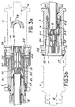
- the connector is seen in the locked position.
- the male part 2 and the female part 6, of cylindrical shape, are crossed in their center by a first and a second coaxial conductors 4 and 8 respectively.
- the first conductor 4 comprises in its center a wire 5 surrounded by an insulator 7, itself surrounded by a metal braid 9, the whole being surrounded by an insulating sheath 10.
- the male part is made integral with the conductor 4 by means of a cable gland 24 surrounding the sheath 10 and coming to be placed at the end of the male part opposite to the female part: the cable gland 24 presses a seal 11 which is supported on the sheath 10 and on the male part 2 ensuring sealing at this end of the connector.
- a cable gland 26 makes the female part 6 integral with the second conductor 8 and seals by means of the seal 13.
- the male part comprises a first electrical connection body 12, one end of which 20 can come into contact with a second electrical connection body 14 secured to the female part.
- the latter comprises two split skirts 16 and 18 between which the end 20 of the body 12 is placed.
- the contact surface between the first skirt 16 and the first connecting body is larger than the contact surface between the latter and the second skirt 18.
- the latter being in electrical contact with both the first skirt 16 and the first connecting body 12, it allows stray currents to flow to ground.
- the contact resistance between this second skirt 18 and the body 12 is significantly greater than the contact resistance between the latter and the outer skirt 16, only a small part of the main current flows through the second skirt 18, which greatly reduces the disturbances induced at the central conductor.
- the second skirt 18 must be in electrical contact both with the first connecting body 12 and with the second connecting body 14 because if one of its ends was free, it would behave like a antenna and the second skirt would no longer play its role of protective screen.
- the electrical continuity of the central conductor is ensured in a conventional manner.
- the wire 5 of the conductor 4 has at its end a male pin to which it is soldered and the central wire of the conductor 8 has at its end a female pin to which it is soldered.
- the male pin enters the female pin, thus ensuring the electrical continuity necessary for the routing of the signal.
- Figure 2 schematically shows the connector locking system according to the invention. It can be seen that the male part comprises a first locking body 28 provided with lugs such as 32 which can cooperate with slots such as 34 formed in a second locking body 30 located on the female part.
- this second locking body 30 is movable relative to a part 40 integral with the female part: elastic means 31, in this case a spring, provide the connection between parts 30 and 40.
- Locking takes place as follows: a first fixed manipulator 43 (fig. 2) holds the female part by means of the locking body 30. A second manipulator 44 grasps the male part and approaches the female part until the front face 41 of the first locking body 28 comes to bear on the front face 42 of the part 40 by compressing the spring 31. The whole of the female part moves back relative to the locking body 30 which remains fixed (fig 3a and 3b).
- the male part is given a rotational movement so that the pins 32 penetrate into the slots 34.
- the shape of these is such that, during this operation, the male part moves back slightly, which allows the spring 31 to relax and apply the front face 42 of the part 40 on the front face 41 of the locking body 28.
- a circular seal 36 located on the front face 41 of the body 28 seals this level of the connector.
- the connector according to the invention has many advantages, starting with the ease and speed of locking, which makes it possible to carry out this operation using remote manipulators.
- the electrical characteristics, tightness and immunity to parasites were the same as those of conventional screw connectors, which allows use in a hazardous, radioactive or corrosive for example.
Landscapes
- Coupling Device And Connection With Printed Circuit (AREA)
- Details Of Connecting Devices For Male And Female Coupling (AREA)
- Connector Housings Or Holding Contact Members (AREA)
Applications Claiming Priority (2)
| Application Number | Priority Date | Filing Date | Title |
|---|---|---|---|
| FR8100801A FR2498382A1 (fr) | 1981-01-16 | 1981-01-16 | Connecteur electrique |
| FR8100801 | 1981-01-16 |
Publications (2)
| Publication Number | Publication Date |
|---|---|
| EP0058580A1 true EP0058580A1 (de) | 1982-08-25 |
| EP0058580B1 EP0058580B1 (de) | 1986-01-08 |
Family
ID=9254243
Family Applications (1)
| Application Number | Title | Priority Date | Filing Date |
|---|---|---|---|
| EP19820400063 Expired EP0058580B1 (de) | 1981-01-16 | 1982-01-14 | Elektrischer Verbinder mit einfacher Verriegelung |
Country Status (3)
| Country | Link |
|---|---|
| EP (1) | EP0058580B1 (de) |
| DE (1) | DE3268341D1 (de) |
| FR (1) | FR2498382A1 (de) |
Cited By (2)
| Publication number | Priority date | Publication date | Assignee | Title |
|---|---|---|---|---|
| GB2249224A (en) * | 1990-09-27 | 1992-04-29 | Gte Prod Corp | Soldered connector for a shielded coaxial cable. |
| US5389666A (en) * | 1991-12-27 | 1995-02-14 | Ono Pharmaceutical Co., Ltd. | Fused benzeneoxyacetic acid derivatives |
Citations (5)
| Publication number | Priority date | Publication date | Assignee | Title |
|---|---|---|---|---|
| CH371164A (de) * | 1959-07-14 | 1963-08-15 | Standard Telephon & Radio Ag | Koaxialstecker |
| US3107135A (en) * | 1961-04-10 | 1963-10-15 | Automatic Metal Products Corp | Electrical connectors for coaxial cables |
| US3209287A (en) * | 1960-08-09 | 1965-09-28 | Bendix Corp | Electrical coaxial cable connecting assembly with impedance matching |
| US3253250A (en) * | 1963-11-26 | 1966-05-24 | Itt | Electrical connector structure |
| US3332052A (en) * | 1965-02-26 | 1967-07-18 | United Carr Inc | Electrical connector component with grounding crown contact |
-
1981
- 1981-01-16 FR FR8100801A patent/FR2498382A1/fr active Granted
-
1982
- 1982-01-14 EP EP19820400063 patent/EP0058580B1/de not_active Expired
- 1982-01-14 DE DE8282400063T patent/DE3268341D1/de not_active Expired
Patent Citations (5)
| Publication number | Priority date | Publication date | Assignee | Title |
|---|---|---|---|---|
| CH371164A (de) * | 1959-07-14 | 1963-08-15 | Standard Telephon & Radio Ag | Koaxialstecker |
| US3209287A (en) * | 1960-08-09 | 1965-09-28 | Bendix Corp | Electrical coaxial cable connecting assembly with impedance matching |
| US3107135A (en) * | 1961-04-10 | 1963-10-15 | Automatic Metal Products Corp | Electrical connectors for coaxial cables |
| US3253250A (en) * | 1963-11-26 | 1966-05-24 | Itt | Electrical connector structure |
| US3332052A (en) * | 1965-02-26 | 1967-07-18 | United Carr Inc | Electrical connector component with grounding crown contact |
Cited By (3)
| Publication number | Priority date | Publication date | Assignee | Title |
|---|---|---|---|---|
| GB2249224A (en) * | 1990-09-27 | 1992-04-29 | Gte Prod Corp | Soldered connector for a shielded coaxial cable. |
| GB2249224B (en) * | 1990-09-27 | 1994-09-14 | Gte Prod Corp | Soldered connector for a shielded coaxial cable |
| US5389666A (en) * | 1991-12-27 | 1995-02-14 | Ono Pharmaceutical Co., Ltd. | Fused benzeneoxyacetic acid derivatives |
Also Published As
| Publication number | Publication date |
|---|---|
| EP0058580B1 (de) | 1986-01-08 |
| FR2498382B1 (de) | 1984-02-24 |
| FR2498382A1 (fr) | 1982-07-23 |
| DE3268341D1 (en) | 1986-02-20 |
Similar Documents
| Publication | Publication Date | Title |
|---|---|---|
| EP0124131B1 (de) | Verlängerungsstück der Seele eines Koaxialkabels und ein mit einem solchen Verlängerungsstück versehener Verbinder | |
| US4173385A (en) | Watertight cable connector | |
| FR2760137A1 (fr) | Connecteur electrique coaxial | |
| FR2492597A1 (fr) | Element de connecteur electrique pour cable blinde a deux conducteurs multibrins | |
| EP0383661B1 (de) | Elektrische Verbindereinrichtung eines Kabels, namentlich Zündkabels, an einer Klemme | |
| FR2667448A1 (fr) | Connecteur soude pour cable coaxial blinde. | |
| EP0500466B1 (de) | Verschluss für die Kontaktaufnahme eines elektrischen oder optischen Steckverbinders | |
| EP0037313B1 (de) | Die Abdichtung elektrischer Verbinder gestattende Geräte | |
| EP0058580B1 (de) | Elektrischer Verbinder mit einfacher Verriegelung | |
| EP0595708B1 (de) | Vorrichtung zum Verhindern des Schwindens der Isolation für kunststoffisolierte Energiekabel | |
| EP0138700B1 (de) | Verbinder für isolierte elektrische Kabel | |
| FR2579837A1 (fr) | Serre-cable pour installations electriques | |
| FR2681732A1 (fr) | Systeme de connexion electrique pour cable plat. | |
| EP0511079B1 (de) | Elektrischer Leistungsstecker | |
| EP3823120A1 (de) | Verbessertes elektrisches anschlusskit | |
| EP0911915A1 (de) | Elektrische Anschlussklemme und Endstück einer Leuchtstoffröhre mit einer solchen Klemme | |
| FR2786033A1 (fr) | Dispositif d'etancheite pour connecteurs de cables et assemblage de connecteur | |
| FR2630577A1 (fr) | Dispositif de mise a la masse de l'armure de cables electriques | |
| FR2478882A1 (fr) | Fiche coaxiale femelle | |
| FR2514577A1 (fr) | Partie arriere de connecteur etanche, avec bague de continuite de masse pour cable blinde, et procede de fabrication de celle-ci | |
| FR2740920A1 (fr) | Dispositif de raccord arriere pour connecteur electrique | |
| FR2981209A1 (fr) | Dispositif de raccordement d'une gaine de blindage de cable | |
| FR3125363A1 (fr) | Dispositif de protection d’un organe de connexion d’un catalyseur de véhicule automobile | |
| EP0016340A1 (de) | Verbindungsvorrichtung zwischen den Aussenleitern zweier koaxialer Paare | |
| FR2652207A1 (fr) | Dispositif de mise a la masse de cables electriques. |
Legal Events
| Date | Code | Title | Description |
|---|---|---|---|
| PUAI | Public reference made under article 153(3) epc to a published international application that has entered the european phase |
Free format text: ORIGINAL CODE: 0009012 |
|
| AK | Designated contracting states |
Designated state(s): DE FR GB IT |
|
| 17P | Request for examination filed |
Effective date: 19830121 |
|
| GRAA | (expected) grant |
Free format text: ORIGINAL CODE: 0009210 |
|
| AK | Designated contracting states |
Designated state(s): DE FR GB IT |
|
| REF | Corresponds to: |
Ref document number: 3268341 Country of ref document: DE Date of ref document: 19860220 |
|
| ITF | It: translation for a ep patent filed | ||
| PLBE | No opposition filed within time limit |
Free format text: ORIGINAL CODE: 0009261 |
|
| STAA | Information on the status of an ep patent application or granted ep patent |
Free format text: STATUS: NO OPPOSITION FILED WITHIN TIME LIMIT |
|
| 26N | No opposition filed | ||
| PG25 | Lapsed in a contracting state [announced via postgrant information from national office to epo] |
Ref country code: GB Effective date: 19890114 |
|
| GBPC | Gb: european patent ceased through non-payment of renewal fee | ||
| PG25 | Lapsed in a contracting state [announced via postgrant information from national office to epo] |
Ref country code: DE Effective date: 19891003 |
|
| PGFP | Annual fee paid to national office [announced via postgrant information from national office to epo] |
Ref country code: FR Payment date: 19930126 Year of fee payment: 12 |
|
| PG25 | Lapsed in a contracting state [announced via postgrant information from national office to epo] |
Ref country code: FR Effective date: 19940930 |
|
| REG | Reference to a national code |
Ref country code: FR Ref legal event code: ST |