EP0058631A1 - Kraftübertragende Getriebeeinheit mit stufenlos regelbaren Geschwindigkeiten - Google Patents
Kraftübertragende Getriebeeinheit mit stufenlos regelbaren Geschwindigkeiten Download PDFInfo
- Publication number
- EP0058631A1 EP0058631A1 EP82630012A EP82630012A EP0058631A1 EP 0058631 A1 EP0058631 A1 EP 0058631A1 EP 82630012 A EP82630012 A EP 82630012A EP 82630012 A EP82630012 A EP 82630012A EP 0058631 A1 EP0058631 A1 EP 0058631A1
- Authority
- EP
- European Patent Office
- Prior art keywords
- gear
- rotor
- gear rack
- axis
- pinion gear
- Prior art date
- Legal status (The legal status is an assumption and is not a legal conclusion. Google has not performed a legal analysis and makes no representation as to the accuracy of the status listed.)
- Withdrawn
Links
- 230000005540 biological transmission Effects 0.000 title claims abstract description 37
- 230000000712 assembly Effects 0.000 claims description 21
- 238000000429 assembly Methods 0.000 claims description 21
- 230000033001 locomotion Effects 0.000 claims description 17
- 239000013598 vector Substances 0.000 claims description 7
- 230000000694 effects Effects 0.000 description 2
- 239000000314 lubricant Substances 0.000 description 2
- 230000014759 maintenance of location Effects 0.000 description 2
- 208000004188 Tooth Wear Diseases 0.000 description 1
- 230000007423 decrease Effects 0.000 description 1
- 238000006073 displacement reaction Methods 0.000 description 1
- 239000012634 fragment Substances 0.000 description 1
- 230000003068 static effect Effects 0.000 description 1
- 210000001114 tooth apex Anatomy 0.000 description 1
Images



Classifications
-
- F—MECHANICAL ENGINEERING; LIGHTING; HEATING; WEAPONS; BLASTING
- F16—ENGINEERING ELEMENTS AND UNITS; GENERAL MEASURES FOR PRODUCING AND MAINTAINING EFFECTIVE FUNCTIONING OF MACHINES OR INSTALLATIONS; THERMAL INSULATION IN GENERAL
- F16H—GEARING
- F16H29/00—Gearings for conveying rotary motion with intermittently-driving members, e.g. with freewheel action
- F16H29/20—Gearings for conveying rotary motion with intermittently-driving members, e.g. with freewheel action the intermittently-acting members being shaped as worms, screws, or racks
-
- Y—GENERAL TAGGING OF NEW TECHNOLOGICAL DEVELOPMENTS; GENERAL TAGGING OF CROSS-SECTIONAL TECHNOLOGIES SPANNING OVER SEVERAL SECTIONS OF THE IPC; TECHNICAL SUBJECTS COVERED BY FORMER USPC CROSS-REFERENCE ART COLLECTIONS [XRACs] AND DIGESTS
- Y10—TECHNICAL SUBJECTS COVERED BY FORMER USPC
- Y10T—TECHNICAL SUBJECTS COVERED BY FORMER US CLASSIFICATION
- Y10T74/00—Machine element or mechanism
- Y10T74/18—Mechanical movements
- Y10T74/18056—Rotary to or from reciprocating or oscillating
- Y10T74/18088—Rack and pinion type
- Y10T74/18096—Shifting rack
-
- Y—GENERAL TAGGING OF NEW TECHNOLOGICAL DEVELOPMENTS; GENERAL TAGGING OF CROSS-SECTIONAL TECHNOLOGIES SPANNING OVER SEVERAL SECTIONS OF THE IPC; TECHNICAL SUBJECTS COVERED BY FORMER USPC CROSS-REFERENCE ART COLLECTIONS [XRACs] AND DIGESTS
- Y10—TECHNICAL SUBJECTS COVERED BY FORMER USPC
- Y10T—TECHNICAL SUBJECTS COVERED BY FORMER US CLASSIFICATION
- Y10T74/00—Machine element or mechanism
- Y10T74/18—Mechanical movements
- Y10T74/1836—Rotary to rotary
Definitions
- the present invention pertains generally to power transmission units of the type having a speed reducing -capability.
- Typical gear equipped transmissions utilize chordally enmeshing gears with selective gear trains providing multiple fixed ratios. Speed changing in such transmissions necessarily results in an interruption of power output during gear shifting. Additionally, the restricted chordal tooth meshing inherent between driving and driven circular gears in conventional transmissions requires that the gears be of substantial length for adequate tooth strength resulting in conventional transmissions being of considerable size and weight. Further, typically transmissions utilize gear trains where speed reduction is by means of axially displaceable gears which require synchronizing means further complicating the transmission mechanism.
- Known transmissions, particularly of the automotive type add substantially to vehicle weight to hinder operating economy.
- the present invention is embodied within a power transmission unit of compact design and providing infinite Speed changes between input and output shafts.
- the present transmission icnludes multiple, rotating gear rack components or assemblies which are powered by a pinion gear.
- the gear rack components impart rotation to a combination rotor and output shaft.
- Linear motion imparted the gear rack components by the driving pinion gear is translated into rotary motion of the rotor by reason of the rack components being confined by the rotor and acting along vectors offset from the rotor axis.
- Speed changes to the cotor and its output shaft result from selectively positioring of the oinion gear toward or away from the rotor axis with maximum speed reduction occurring at the extreme of pinion gear displacement away from the rotor axis.
- the gear rack components are each of elongate, open frame-like configuration each having a pair of opposed rack gears oppositely spaced from the pinion gear.
- a crescent shaped cam structure serves to isolate one rack gear of the pair from the pinion gear while simultaneously causing its companion rack gear of the pair to rotate into pinion engagement. Accordingly, positioning of the pinion relative the axis of rotor rotation accomplishes a speed change by reason of the pinion enmeshing with a lessor or greater number of rack teeth.
- the rack gears are preferably spring mounted within each gear rack assembly in a manner permitting relative movement therebetween for meshing purposes.
- the gear rack assembly ends are each bearing equipped.
- the cam structure includes bearing rings.
- the present invention is embodied within a power transmission unit comprising, a housing, a power input shaft, a speed selector assembly adjustably carried by the housing and including gear means, said gear means including a pinion gear powered by said input shaft, a rotor, a power output shaft driven by said rotor, gear rack assemblies within said housing.and in endwise driving engagement with said rotor, said pinion gear adapted to impart motion to the gear rack assemblies, a cam structure movable with the speed selector assembly and acting on said gear rack components, and said speed selector assembly positionable so as to locate the rotational axis of said pinion gear proximate the axis of rotor rotation, said speed selector additionally positionable to locate the pinion gear axis away from the axis of rotor rotation whereat the pinion gear sequentially drives the gear rack assemblies along vectors offset from the axis of rotor rotation whereby a speed reduction is effected between the power input and output shafts.
- gear means including a pinion gear powered by said
- the reference numeral 1 indicates a transmission case or housing of circular configuration closed by a cover plate 2. Said housing is suitably charged with a quantity of lubricant and with mounting means (not shown) for securement to a support such as a vehicle frame.
- the selector assembly includes a gear carrier body at 5 flanged at 5A on which flange retainers 6 act to permit adjusted rotational movement of body 5 about an axis at A in response to movement of a speed control member at 4.
- Gear means associated with the speed selector assembly include a drive gear 7 on a power input shaft 8.
- a driven gear 10 in mesh with drive gear 7 is a driven gear 10 on a shaft 11 suitably journaled within the positionable carrier body.
- a pinion gear 12 (Fig.3). From the ' foregoing it will be seen that upon arcuate positioning of selector body 5 gears 10 and 12 will be positioned about axis A.
- cam structure 13 of crescent shape and located within housing 1 and partially circumpos- ed about pinion gear 12.
- a cam outer surface is at 13A. Said cam surface acts on later described gear rack components to constrain same for rotational movement into and out of arcuate mesh with pinion gear 12.
- Cam 13 overlies approximately one-half of the pinion gear periphery.
- Axis B constitutes the axis of rotation for driven gear 10, shaft 11 and pinion gear 12 and is offset from axis A and positionable thereabout upon arcuate positioning of carrier body 5 by control 4.
- Cam 13 is also positionable about axis A during arcuate positioning of the carrier body.
- Cam surface 13A is formed about an axis C (Fig. 4) offset from axis B of pinion gear 12.
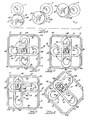
- First and second gear rack components or assemblies are cruciformly disposed and indicated respectively at 16 and 17 each shown as being of elongate plate shape and each defining a lengthwise extending opening 16A-17A.
- Paired gear racks thereon at 20-21 and 22-23 are spaced parallel to each other to receive therebetween pinion gear 12 and cam 13.
- Each gear rack component or assembly is slidably confined at its ends 16B-16C and 17B-17C within and contributes to driving a rotor plate of pan shape generally at 18 having an outer perimetrical wall 19. Said rotor drives a power output shaft at 24. Rotor corners Cl through C4 are indicated infigures 5 through 11 for purposes of understanding rotor rotation.
- the opposed or companion gear racks at 20-21 each extends substantially the length of component opening 16A.
- companion gear racks at 22 and 23 on component 17 extend the length of opening 17A.
- the gear racks of each pair are oppositely spaced from one another a distance permitting full engagement of one gear rack with pinion gear 12 while the remaining gear rack of the pair slidably engages cam surface 13A.
- Cam structure 13 accordingly constrains each gear rack component 16 and 17 to revolve about axis C of cam surface 13A, during which rotation, the cam surface acting on one gear rack of the pair with the pinion gear teeth engaging the remaining gear rack of the pair.
- powered pinion gear 12 is disposed coaxially with axis D of rotor 18.
- rotating pinion gear 12 will be in static mesh with one or both gear rack components in a fixed relationship therewith.
- the rotational speed of pinion gear 12, gear rack components 16 and 17 and rotor 18 is uniform. Movement of gear rack components 16 and 17 is rotational only with no relative movement between the gear rack components and the rotor.
- Speed reduction of output shaft 24 relative input shaft 8 is effected by movement of speed control body 5 by control member 4.
- Pinion gear 12 is thereby positioned about axis A so as to be offset from rotor axis D. Forces are applied singly by the pinion to one of the two gear racks of each gear rack component 16 or 17 and are applied along a vector V offset from rotor axis D to impart clockwise rotation to the rotor per Figures 7 through 11 . In the extreme displaced position of pinion gear 12 (from rotor axis D) maximum speed reduction is effected. The pinon gear when so positioned will mesh with substantially all of the teeth of each gear rack.
- Control member 4 may be manually positioned or coupled to torque sensing means with provision made for automatic positioning of the control member in response to changing torque loads on the transmission. Further, the present transmission may be used in series with one or more additional like transmissions for greater speed reduction.
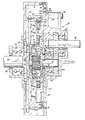
- the transmission case 31 is closed by a circular cover plate 32 to define a chamber receiving a quantity of lubricant.
- a speed selector assembly generally at 33 is rotatably confined within a cover plate opening 32A.
- the selector assembly includes a gear carrier body 35 flanged at 35A for retention by a retainer ring 36 permitting arcuate movement of the body about an axis A'.
- a drive gear 37 of the selector assembly is carried by a power input shaft 38 with said gear in mesh with a driven gear 40 on a shaft 41 at the opposite end of which is fixed a pinion gear 42.
- Gears 40 and 42 and their common shaft 41 rotate about an axis B' and are positionable about axis A' during arcuate positioning of the speed selector assembly 33 by a control arm 34.
- Power input shaft 38 is journaled within a bearing assembly 39 while driven shaft 41 is journaled within a bearing assembly at 45.
- cam structure 43 disposed in close proximity to pinion gear 42.
- Cam structure 43 is secured to gear carrier body 35 by ring 44 and fasteners as at 46 and locking screws 46A.
- the cam structure includes circular portions 47 and 48 and an intermediate crescent shaped portion 49.
- the cam structure further includes bearing rings 50 and 51 inset within shouldered areas of circular cam portions 47 and 48. Said rings are disposed about an axis C' which moves with adjusted movement of the speed selector assembly.
- the crescent shaped portion constitutes a bridge between the circular cam portions and overlies approximately 180 degrees of pinion gear 42. Pinion gear 42 at all times has several teeth radially offset from bearing rings 50-51.
- Bearing rings 50 and 51 provide surfaces about which rail edges of later described gear rack assemblies ride during assembly rotation.
- the outer end of pinion carrying shaft 41 is supported within a bushing 52 within the outermost end of the cam structure.
- a retainer washer 53 confines said bushing and the outermost bearing ring 51.
- First and second gear rack assemblies generally at 56 and 57 are disposed perpendicular or crosswise to one another in the manner earlier described with each of said assemblies having a pair of spaced apart gear racks thereon at 60 and 61 and at 62 and 63.
- the racks of each pair are oppositely disposed in parallel with the earlier described pinion gear and cam structure therebetween.
- the gear racks 60-61 and 62-63 are resiliently supported by spiral springs S which are confined within aligned recesses formed in the underside of the gear racks and in parallel rail members 64-65 and 66-67 of each gear rack assembly.
- the rail members of each assembly are of right angle shape in section with inwardly facing load bearing edges at 68-69 and 70-71 which rotatably ride on the bearing rings of the earlier ' described cam structure.
- Keepers (not shown) on the rail member ends overlie the ends of each gear rack and confine the racks for limited movement in a single plane relative their respective rail member.
- Normally the gear rack and its rail member are coplanar .
- the rack supporting springs S permit each gear rack to yield during meshing with pinion gear 42 in those isolated instances where initial gear rack tooth and pinion tooth contact is at the tooth apices. By resiliently mounting each gear rack, the same may yield in this instance thus minimizing tooth wear.
- wall structures 76-77 and 78-79 secured thereto as by recessed fasteners 80.
- Said wall structures are symmetrically disposed on rotor plate 75 with respect to rotor plate axis D' in opposing, parallel pairs with each pair confining a gear rack assembly which is in endwise sliding contact therewith.
- the wall structures are each shouldered as at 81 to slidably receive the associated rack assembly end.
- a plate 74 is secured along each wall structure.
- Each rack assembly end is machined to provide an endless raceway 82 occupied by circulating ball bearing elements 83.
- a closure plate as at 84 is suitably secured to the gear rack assembly end for bearing retention.
- Wall structure 76, and specifically the shouldered portion 81 thereof, constitutes a bearing surface on which the end of the rack assembly acts.
- Circular rotor plate 75 is carried by a transmission output shaft 85 flanged at 86 for the reception of plate fasteners at 87.
- a bearing housing 88 is suitably secured to the transmission housing and retains a seal 89 and a bearing assembly 90 for said output shaft.
- Circular rotor plate 75 and output shaft 85 are concentric with an axis D'.
- cam axis C' and rotoracis D' are aligned as the transmission input and output shafts are set in a one-to-one ratio with no relative movement between the gear rack assemblies nor the rotor structure.
- Arcuate rotation of speed selector assembly 33 will result in pinion gear 42 being displaced about axis A' in the manner described in conjunction with the first described transmission unit.
- Positioning of pinion gear axis B' to the extreme (remote from rotor axis D') will result in maximum speed reduction ratio between input and output shafts.
- Such positioning of pinion gear 42 away from rotor axis D' will cause said gear to mesh with a greater number of gear rack teeth during the momentary gear rack engagement to, in effect, provide a transmission "low gear" ratio.
- the input-output shaft ratio decreases with a one-to-one ratio effected when the pinion gear axis is in substantial alignement with rotor axis D'. In this instance no relative movement occurs between the gear rack assemblies nor between same and the rotor structure.
Landscapes
- Engineering & Computer Science (AREA)
- General Engineering & Computer Science (AREA)
- Mechanical Engineering (AREA)
- Transmission Devices (AREA)
- Gear Transmission (AREA)
Applications Claiming Priority (4)
| Application Number | Priority Date | Filing Date | Title |
|---|---|---|---|
| US23541781A | 1981-02-17 | 1981-02-17 | |
| US235417 | 1981-02-17 | ||
| US322950 | 1981-11-19 | ||
| US06/322,950 US4411165A (en) | 1981-02-17 | 1981-11-19 | Power transmission unit with infinite speeds |
Publications (1)
| Publication Number | Publication Date |
|---|---|
| EP0058631A1 true EP0058631A1 (de) | 1982-08-25 |
Family
ID=26928890
Family Applications (1)
| Application Number | Title | Priority Date | Filing Date |
|---|---|---|---|
| EP82630012A Withdrawn EP0058631A1 (de) | 1981-02-17 | 1982-02-15 | Kraftübertragende Getriebeeinheit mit stufenlos regelbaren Geschwindigkeiten |
Country Status (7)
| Country | Link |
|---|---|
| US (1) | US4411165A (de) |
| EP (1) | EP0058631A1 (de) |
| AR (1) | AR227461A1 (de) |
| AU (1) | AU8056182A (de) |
| BR (1) | BR8200804A (de) |
| DK (1) | DK53482A (de) |
| ES (1) | ES509695A0 (de) |
Cited By (4)
| Publication number | Priority date | Publication date | Assignee | Title |
|---|---|---|---|---|
| EP0380828A1 (de) * | 1987-05-07 | 1990-08-08 | Nutec Transmission Ltd. | Leistungsübertragungsgerät |
| WO1991010081A1 (en) * | 1989-12-22 | 1991-07-11 | Nutec Transmission Ltd. | Continuously variable transmission |
| EP0760334A1 (de) * | 1995-08-31 | 1997-03-05 | Keiichi Akashi | Gangschaltungssystem |
| DE19538510A1 (de) * | 1995-10-04 | 1997-04-10 | Wilhelm Wingensiefen | Taumelantrieb Verstellgetriebe zur Übertragung einer Drehbewegung in eine translatorische Bewegung mit hohem Übersetzungsverhältnis |
Families Citing this family (9)
| Publication number | Priority date | Publication date | Assignee | Title |
|---|---|---|---|---|
| US4475412A (en) * | 1983-06-07 | 1984-10-09 | Evans Lyle B | Infinite speed power transmission with shiftable gear plates |
| US4782548A (en) * | 1987-08-24 | 1988-11-08 | Wong Edward Y | Linear-motion wiper structure for windshield and like surface |
| US5129272A (en) * | 1989-12-22 | 1992-07-14 | Nutec Transmission Ltd. | Continuously variable transmission |
| SE465176B (sv) * | 1990-06-07 | 1991-08-05 | Matti Pesonen | Fluidummotor samt drivaggregat foer en fluidummoto r |
| US5498053A (en) * | 1994-03-25 | 1996-03-12 | Jay Roberts Company | Reciprocating plate mechanism |
| US5934243A (en) * | 1998-03-26 | 1999-08-10 | Kopystanski; George | Drive mechanism for a reciprocating piston engine |
| US7515508B1 (en) * | 2008-03-12 | 2009-04-07 | Timex Group B.V. | Indicator assembly for a wearable electronic device |
| US8567270B1 (en) * | 2011-01-11 | 2013-10-29 | Stephen E. Pileeki | Infinitely variable reciprocating transmission apparatus |
| CN116104922B (zh) * | 2023-04-12 | 2023-06-30 | 西安高商智能科技有限责任公司 | 一种驱动减速机构 |
Citations (3)
| Publication number | Priority date | Publication date | Assignee | Title |
|---|---|---|---|---|
| FR437830A (fr) * | 1911-11-30 | 1912-05-01 | Edouard Felix Michel Abrard | Changement de vitesse |
| FR766638A (de) * | 1934-06-29 | |||
| US3087355A (en) * | 1959-01-06 | 1963-04-30 | Bassereau Roger Jules Justin | Constantly variable speed transmission |
Family Cites Families (11)
| Publication number | Priority date | Publication date | Assignee | Title |
|---|---|---|---|---|
| FR340544A (fr) | 1904-02-17 | 1904-07-08 | Joseph Beaux | Système de transmission de mouvement |
| FR527598A (fr) | 1920-10-22 | 1921-10-27 | Pierre Valin | Système d'accouplement réducteur, multiplicateur et additionneur de vitesse |
| US1435838A (en) * | 1921-01-17 | 1922-11-14 | Ernest L Fantus | Crank transmission mechanism |
| DE625053C (de) | 1934-04-12 | 1936-02-03 | Wilhelm Schick | Aus Gleitschiene und auf ihr verschiebbaren Zugbolzen bestehender Radabzieher |
| US2069007A (en) * | 1934-07-16 | 1937-01-26 | Fontana Cesare | Device for automatically changing transmission ratio |
| FR854189A (fr) * | 1938-12-21 | 1940-04-06 | Changement de vitesse | |
| US3490299A (en) * | 1968-06-19 | 1970-01-20 | Tihamer S Binner | Infinitely variable ratio rotary drive |
| SU381833A1 (ru) | 1969-05-28 | 1973-05-22 | Кемеровский межотраслевой научно исследовательский , проектно технологический институт автоматизации , механизации машиностроени | Импульсивный вариатор скорости12 |
| US3750485A (en) * | 1971-09-16 | 1973-08-07 | J Blakemore | Infinitely variable positive mechanical transmission |
| US3913749A (en) * | 1974-08-12 | 1975-10-21 | Fluoroware Systems Corp | Wafer basket transfer apparatus |
| SU715863A1 (ru) | 1977-06-10 | 1980-02-15 | Рижский Краснознаменный Институт Инженеров Гражданской Авиации Им. Ленинского Комсомола | Вариатор скорости |
-
1981
- 1981-11-19 US US06/322,950 patent/US4411165A/en not_active Expired - Fee Related
-
1982
- 1982-02-09 DK DK53482A patent/DK53482A/da not_active Application Discontinuation
- 1982-02-15 BR BR8200804A patent/BR8200804A/pt unknown
- 1982-02-15 EP EP82630012A patent/EP0058631A1/de not_active Withdrawn
- 1982-02-17 ES ES509695A patent/ES509695A0/es active Granted
- 1982-02-17 AR AR227461A patent/AR227461A1/es active
- 1982-02-17 AU AU80561/82A patent/AU8056182A/en not_active Abandoned
Patent Citations (3)
| Publication number | Priority date | Publication date | Assignee | Title |
|---|---|---|---|---|
| FR766638A (de) * | 1934-06-29 | |||
| FR437830A (fr) * | 1911-11-30 | 1912-05-01 | Edouard Felix Michel Abrard | Changement de vitesse |
| US3087355A (en) * | 1959-01-06 | 1963-04-30 | Bassereau Roger Jules Justin | Constantly variable speed transmission |
Cited By (5)
| Publication number | Priority date | Publication date | Assignee | Title |
|---|---|---|---|---|
| EP0380828A1 (de) * | 1987-05-07 | 1990-08-08 | Nutec Transmission Ltd. | Leistungsübertragungsgerät |
| WO1991010081A1 (en) * | 1989-12-22 | 1991-07-11 | Nutec Transmission Ltd. | Continuously variable transmission |
| EP0760334A1 (de) * | 1995-08-31 | 1997-03-05 | Keiichi Akashi | Gangschaltungssystem |
| CN1059735C (zh) * | 1995-08-31 | 2000-12-20 | 明石桂一 | 变速装置 |
| DE19538510A1 (de) * | 1995-10-04 | 1997-04-10 | Wilhelm Wingensiefen | Taumelantrieb Verstellgetriebe zur Übertragung einer Drehbewegung in eine translatorische Bewegung mit hohem Übersetzungsverhältnis |
Also Published As
| Publication number | Publication date |
|---|---|
| BR8200804A (pt) | 1982-12-21 |
| ES8304281A1 (es) | 1983-02-16 |
| ES509695A0 (es) | 1983-02-16 |
| AR227461A1 (es) | 1982-10-29 |
| AU8056182A (en) | 1982-08-26 |
| US4411165A (en) | 1983-10-25 |
| DK53482A (da) | 1982-08-18 |
Similar Documents
| Publication | Publication Date | Title |
|---|---|---|
| US4411165A (en) | Power transmission unit with infinite speeds | |
| EP0207206B1 (de) | Untersetzungsgetriebe ohne Verzahnung | |
| CA1192762A (en) | Gearing mechanism | |
| US4228698A (en) | Speed reducer | |
| US5692989A (en) | Self aligning planetary gear transmission & speed reducer | |
| US4524644A (en) | Counterweight for orbital drive mechanism | |
| EP0004461A1 (de) | Stufenloses Getriebe | |
| US3776051A (en) | Rotary motion transmitting device | |
| RU95115809A (ru) | Редуктор с циклоидальным зацеплением | |
| US3587350A (en) | Power transmission including friction drive and gear drive | |
| US4843899A (en) | Gear drive with infinitely variable transmission ratio | |
| EP0378978A2 (de) | Zahnradgetriebe | |
| WO1998036189A1 (en) | Compound oscillatory roller transmission | |
| CA1065163A (en) | Epicyclic cog belt speed reducer | |
| US2580392A (en) | Variable-speed transmission | |
| US3349642A (en) | Variable speed transmission | |
| JPH0541999Y2 (de) | ||
| SU1372130A1 (ru) | Передача дл параллельных валов | |
| US2656737A (en) | Gearless speed reduction mechanism | |
| US2109695A (en) | Variable speed transmission | |
| SU1184998A1 (ru) | Фрикционный планетарный вариатор с коническими колесами | |
| SU1364792A1 (ru) | Планетарна зубчато-винтова сферическа передача | |
| JPH0396739A (ja) | 高速回転軸支持装置 | |
| JPS5969556A (ja) | 自動変速装置 | |
| SU1153149A1 (ru) | Редуктор |
Legal Events
| Date | Code | Title | Description |
|---|---|---|---|
| PUAI | Public reference made under article 153(3) epc to a published international application that has entered the european phase |
Free format text: ORIGINAL CODE: 0009012 |
|
| AK | Designated contracting states |
Designated state(s): AT BE CH DE FR GB IT LU NL SE |
|
| STAA | Information on the status of an ep patent application or granted ep patent |
Free format text: STATUS: THE APPLICATION IS DEEMED TO BE WITHDRAWN |
|
| 18D | Application deemed to be withdrawn |
Effective date: 19830731 |