EP0058667B1 - Vorrichtung zur teilung eines laserbündels - Google Patents
Vorrichtung zur teilung eines laserbündels Download PDFInfo
- Publication number
- EP0058667B1 EP0058667B1 EP81901289A EP81901289A EP0058667B1 EP 0058667 B1 EP0058667 B1 EP 0058667B1 EP 81901289 A EP81901289 A EP 81901289A EP 81901289 A EP81901289 A EP 81901289A EP 0058667 B1 EP0058667 B1 EP 0058667B1
- Authority
- EP
- European Patent Office
- Prior art keywords
- grating
- beams
- substrate
- parallel
- equidistant
- Prior art date
- Legal status (The legal status is an assumption and is not a legal conclusion. Google has not performed a legal analysis and makes no representation as to the accuracy of the status listed.)
- Expired
Links
Images

Classifications
-
- G—PHYSICS
- G01—MEASURING; TESTING
- G01J—MEASUREMENT OF INTENSITY, VELOCITY, SPECTRAL CONTENT, POLARISATION, PHASE OR PULSE CHARACTERISTICS OF INFRARED, VISIBLE OR ULTRAVIOLET LIGHT; COLORIMETRY; RADIATION PYROMETRY
- G01J3/00—Spectrometry; Spectrophotometry; Monochromators; Measuring colours
- G01J3/12—Generating the spectrum; Monochromators
- G01J3/18—Generating the spectrum; Monochromators using diffraction elements, e.g. grating
- G01J3/1804—Plane gratings
-
- G—PHYSICS
- G02—OPTICS
- G02B—OPTICAL ELEMENTS, SYSTEMS OR APPARATUS
- G02B27/00—Optical systems or apparatus not provided for by any of the groups G02B1/00 - G02B26/00, G02B30/00
- G02B27/10—Beam splitting or combining systems
- G02B27/1006—Beam splitting or combining systems for splitting or combining different wavelengths
-
- G—PHYSICS
- G02—OPTICS
- G02B—OPTICAL ELEMENTS, SYSTEMS OR APPARATUS
- G02B27/00—Optical systems or apparatus not provided for by any of the groups G02B1/00 - G02B26/00, G02B30/00
- G02B27/10—Beam splitting or combining systems
- G02B27/106—Beam splitting or combining systems for splitting or combining a plurality of identical beams or images, e.g. image replication
-
- G—PHYSICS
- G02—OPTICS
- G02B—OPTICAL ELEMENTS, SYSTEMS OR APPARATUS
- G02B27/00—Optical systems or apparatus not provided for by any of the groups G02B1/00 - G02B26/00, G02B30/00
- G02B27/10—Beam splitting or combining systems
- G02B27/1086—Beam splitting or combining systems operating by diffraction only
-
- G—PHYSICS
- G02—OPTICS
- G02B—OPTICAL ELEMENTS, SYSTEMS OR APPARATUS
- G02B27/00—Optical systems or apparatus not provided for by any of the groups G02B1/00 - G02B26/00, G02B30/00
- G02B27/10—Beam splitting or combining systems
- G02B27/1086—Beam splitting or combining systems operating by diffraction only
- G02B27/1093—Beam splitting or combining systems operating by diffraction only for use with monochromatic radiation only, e.g. devices for splitting a single laser source
-
- G—PHYSICS
- G02—OPTICS
- G02B—OPTICAL ELEMENTS, SYSTEMS OR APPARATUS
- G02B27/00—Optical systems or apparatus not provided for by any of the groups G02B1/00 - G02B26/00, G02B30/00
- G02B27/10—Beam splitting or combining systems
- G02B27/12—Beam splitting or combining systems operating by refraction only
- G02B27/126—The splitting element being a prism or prismatic array, including systems based on total internal reflection
-
- G—PHYSICS
- G02—OPTICS
- G02B—OPTICAL ELEMENTS, SYSTEMS OR APPARATUS
- G02B27/00—Optical systems or apparatus not provided for by any of the groups G02B1/00 - G02B26/00, G02B30/00
- G02B27/42—Diffraction optics, i.e. systems including a diffractive element being designed for providing a diffractive effect
- G02B27/4233—Diffraction optics, i.e. systems including a diffractive element being designed for providing a diffractive effect having a diffractive element [DOE] contributing to a non-imaging application
- G02B27/4244—Diffraction optics, i.e. systems including a diffractive element being designed for providing a diffractive effect having a diffractive element [DOE] contributing to a non-imaging application in wavelength selecting devices
-
- G—PHYSICS
- G02—OPTICS
- G02B—OPTICAL ELEMENTS, SYSTEMS OR APPARATUS
- G02B27/00—Optical systems or apparatus not provided for by any of the groups G02B1/00 - G02B26/00, G02B30/00
- G02B27/42—Diffraction optics, i.e. systems including a diffractive element being designed for providing a diffractive effect
- G02B27/4272—Diffraction optics, i.e. systems including a diffractive element being designed for providing a diffractive effect having plural diffractive elements positioned sequentially along the optical path
-
- G—PHYSICS
- G02—OPTICS
- G02F—OPTICAL DEVICES OR ARRANGEMENTS FOR THE CONTROL OF LIGHT BY MODIFICATION OF THE OPTICAL PROPERTIES OF THE MEDIA OF THE ELEMENTS INVOLVED THEREIN; NON-LINEAR OPTICS; FREQUENCY-CHANGING OF LIGHT; OPTICAL LOGIC ELEMENTS; OPTICAL ANALOGUE/DIGITAL CONVERTERS
- G02F1/00—Devices or arrangements for the control of the intensity, colour, phase, polarisation or direction of light arriving from an independent light source, e.g. switching, gating or modulating; Non-linear optics
- G02F1/29—Devices or arrangements for the control of the intensity, colour, phase, polarisation or direction of light arriving from an independent light source, e.g. switching, gating or modulating; Non-linear optics for the control of the position or the direction of light beams, i.e. deflection
-
- H—ELECTRICITY
- H01—ELECTRIC ELEMENTS
- H01S—DEVICES USING THE PROCESS OF LIGHT AMPLIFICATION BY STIMULATED EMISSION OF RADIATION [LASER] TO AMPLIFY OR GENERATE LIGHT; DEVICES USING STIMULATED EMISSION OF ELECTROMAGNETIC RADIATION IN WAVE RANGES OTHER THAN OPTICAL
- H01S3/00—Lasers, i.e. devices using stimulated emission of electromagnetic radiation in the infrared, visible or ultraviolet wave range
- H01S3/005—Optical devices external to the laser cavity, specially adapted for lasers, e.g. for homogenisation of the beam or for manipulating laser pulses, e.g. pulse shaping
Definitions
- the invention relates to a device for subdividing a light beam, preferably a laser beam into a plurality of parallel and equidistant beams, or for combining a plurality of beams into one beam.
- Translucent mirrors can conceivably be utilized to subdivide a laser beam into parallel beams, these mirrors being arranged at predetermined mutual spacing after each other in the path of the beam which is to be divided. These mirrors are then arranged mutually parallel and at an oblique angle to the path of the beam. At each such mirror, a part of the beam will be deflected and another part of it will be transmitted through the respective mirror. The reflected beams will be parallel if the mirrors can be adjusted to mutual parallelism, and the distance between the reflected beams can be made equidistant by making the mutual spacing between the parallel mirrors constant.
- Such an apparatus is, however, extremely difficult to adjust for providing a division of the laser beam into parallel equidistant beams, and it is hard to conceive that it could be practically usable.
- One object of the invention is therefore to provide a device of the type mentioned in the introduction, which has a robust embodiment and can afford a high degree of parallelism and equidistance between divided beams or the reverse, can be produced at low cost, can afford a simple possibility of varying the distance between the divided beams, or beams which are to be put together, and can afford the possibility of generating an array or a matrix of beams, which can thereby to advantage be parallel and equidistant in rows, or can afford the possibility of combining a matrix of such beams into a single beam.
- the device according to the invention is useful either for dividing a light beam into a plurality of parallel and equidistant beams or for combining a plurality of parallel and equidistant beams into a single beam.
- the device when used for dividing a light beam especially a laser beam into a plurality of parallel and equidistant beams by using an optical grating, the device is characterized by a transparent substrate with two planar parallel surfaces, the grating being arranged on one of said surfaces of the substrate, the beam to be divided being arranged to be taken in directly through the grating at an input comprising a grating area wherein the grating efficiency is made higher than outside said grating area, the grating line density being chosen wherein
- the device can then be provided with a vapour deposited reflective coating covering the grating surface facing away from the substrate, except at the input.
- the device is, for said use, characterized by a transparent substrate with two planar parallel surfaces, the grating being a transmission grating arranged on one of said surfaces of the substrate, the beam to be divided being arranged to be taken in through the other of said substrate surfaces at an input comprising a grating area wherein the grating efficiency is made higher than outside said grating area, and a reflective coating covering the grating surface facing away from the substrate in said grating area, the grating line density being chosen wherein
- the grating includes two or more sets of lines intersecting each other, the lines in each set of lines being parallel and equidistant, whereby a beam taken in through the input can be divided into a field of parallel equidistant beams arranged in rows.
- the mutual distance of the beams to be combined must be correctly related to the substrate thickness and grating density so that the combined beam exits at said output when the beams to be combined are directed directly onto said other substrate surface.
- the grating can be made with a greater efficiency (deeper grating scores) at the input than in an area surrounding the input.
- the grating comprises two or more sets of lines crossing each other, the lines in each set are mutually parallel and equidistant, whereby a beam can be divided into a field of parallel equidistant beams in rows, or a field of parallel equidistant beams in rows can be combined to a single beam.
- a grating with more than two sets of grating lines can be used. It will thus be possible, for example, to produce from a single beam an array of beams which form a selected spot pattern.
- the substrate can comprise so-called float glass, the chief surfaces of which form said surfaces.
- Float glass is commercially available and has a very high degree of parallelism between its surfaces, and can be utilized as initial material in manufacturing the inventive device.
- the glass is cut to a size suitable for the purpose, the grating or gratings being applied to one surface of the glass plate by some suitable method, e.g. holographic exposure and photoresist etching. This grating can then be made as a transmission grating.
- a reflecting coating is then applied to the grating, e.g. by silver being applied through vaporization, a recess or opening suitably being arranged in the reflecting coating.
- the parallelism of the beams is determined . by how flat the substrate is.
- the angle of incidence of the laser beam to the grating it is possible continuously to vary the distance between the beams, while the beams remain parallel and equidistant.
- the desired distance between the beams can be provided by suitable selection of the grating frequency (pitch of the lines) and/or thickness of the substrate.
- the intensity of the beams can be selected by making the grating with a suitable efficiency, e.g. by suitable selection of the grating profile depth.
- the inventive device can be made with very small dimensions.
- the width of the device is determined by the maximum diameter of the laser beam, and its length by the desired distance between the outmost beams in the row.
- the thickness of the device often only attains some millimeters.
- its superficial dimensions are determined by the distance between the outmost beams in crossing rows.
- the device in accordance with the invention has many fields of application. It can thus be utilized for educational purposes to demonstrate the path of rays in optical components. It can also be utilized for general measuring purposes. It can further be used for inspection purposes (shadowing). It can even be used as a so-called beam expander, which signifies that a beam is divided up into a plurality of parallel beams having small mutual spacing, so that they practically define a straight line. This constitutes a considerable simplification of previous attempts to provide a "band of light", when it was necessary to utilize an oscillating deflection mirror and when poorer light intensity was obtained.
- two substantially like devices in accordance with the invention can be utilized for digital indication of lateral displacement.
- the condition here is that the beam-combining (receiving) device has an "output" with small dimensions relative the combined emitted beam.
- the device can furthermore be utilized for so-called multiplexing, and by providing line fields or grids with special configurations it can be utilized to great advantage for testing lenses.
- Any kind of diffracting apparatus at all can thus be used, even holograms, so that any kind of light distribution can be generated (within the condition of total reflection and conditions for diffraction geometry), e.g. even dot spirals or image multiplexing.
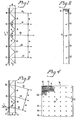
- a float glass plate 2 on which a grating 3 is arranged.
- a reflecting layer 4 is applied to the grating 3.
- An opening 5 is arranged through the layer 4.
- a laser beam 1, which is to be divided, is taken normal to the main surfaces of the substrate 2 through the opening 5.
- the grating 3 is made as a transmission grating, and at the opening 5 the beam 1 is divided into three components.
- a first component is transmitted straight through the grating and forms a beam 12, which constitutes a straight continuation of the beam 1.
- the beam 1 will further be diffracted by the grating 3 to form two beams 11. These two beams 11 extend at an angle f3 to the path of the beam 1.
- the beams 11 will be totally reflected and redirected to the grating 3 at the points B.
- the grating 3 is there provided with a reflecting material so that it functions as a reflection grating.
- the incident beam is divided into three parts.
- a first part is reflected at the angle ⁇ .
- a second part 12 is diffracted perpendicular to the grating 3 and a third part is diffracted back again at the angle ⁇ .
- the perpendicularly diffracted light 12 is parallel to the beam 1 and the undeflected transmitted component 12 of the beam 1.
- the same division in a closely adjacent point B as in the first-mentioned point B whereby a further parallel beam 12 is created. This division is repeated an arbitrary number of times, both upwards and downwards in Fig. 1.
- a tested embodiment of a device in Fig. 1 and 2 had the following data:
- the opening 5 was situated at half the length of the glass 2, whereby seven parallel beams 12 were formed.
- the following relationship is generally applicable:
- the condition for total reflection at A is this condition limiting a to
- a can be continually varied between 13.8 mm and 55 mm by varying ⁇ between 8° and -19°.
- Fig. 4 there is shown a front view of an embodiment of a device with two gratings 3 and 3A, intersecting each other at right angles.
- the opening 5 is arranged substantially centrally.
- the divided beams 12 are parallel and equidistant in rows.
- the distance between the beams 1 in the rows 14 is in response to the line density of the grating 3.
- the distance between beams in the rows 15 are in response to the line density A of the grating 3A.
- Fig. 5 illustrates an embodiment where the beam 1, which is to be divided, is taken in through the substrate 2 and through a deeper grating portion 3', and then to the reflecting layer 4, whereafter diffracted rays eventually coact with a shallower grating portion 3 surrounding the "input" 5.
Landscapes
- Physics & Mathematics (AREA)
- General Physics & Mathematics (AREA)
- Optics & Photonics (AREA)
- Spectroscopy & Molecular Physics (AREA)
- Electromagnetism (AREA)
- Nonlinear Science (AREA)
- Plasma & Fusion (AREA)
- Engineering & Computer Science (AREA)
- Diffracting Gratings Or Hologram Optical Elements (AREA)
- Spectrometry And Color Measurement (AREA)
- Lasers (AREA)
- Analysing Materials By The Use Of Radiation (AREA)
- Laser Surgery Devices (AREA)
Claims (8)


Applications Claiming Priority (2)
| Application Number | Priority Date | Filing Date | Title |
|---|---|---|---|
| SE8003968 | 1980-05-28 | ||
| SE8003968A SE421568B (sv) | 1980-05-28 | 1980-05-28 | Anordning for uppdelning av en ljusstrale i ett flertal stralar eller omvent |
Publications (2)
| Publication Number | Publication Date |
|---|---|
| EP0058667A1 EP0058667A1 (de) | 1982-09-01 |
| EP0058667B1 true EP0058667B1 (de) | 1984-08-08 |
Family
ID=20341057
Family Applications (2)
| Application Number | Title | Priority Date | Filing Date |
|---|---|---|---|
| EP81900924A Expired EP0059706B1 (de) | 1980-05-28 | 1981-03-30 | Dispersives optisches gerät |
| EP81901289A Expired EP0058667B1 (de) | 1980-05-28 | 1981-05-26 | Vorrichtung zur teilung eines laserbündels |
Family Applications Before (1)
| Application Number | Title | Priority Date | Filing Date |
|---|---|---|---|
| EP81900924A Expired EP0059706B1 (de) | 1980-05-28 | 1981-03-30 | Dispersives optisches gerät |
Country Status (8)
| Country | Link |
|---|---|
| US (2) | US4591270A (de) |
| EP (2) | EP0059706B1 (de) |
| JP (2) | JPS57500998A (de) |
| AT (2) | ATE9041T1 (de) |
| AU (1) | AU7036181A (de) |
| DE (2) | DE3165503D1 (de) |
| SE (1) | SE421568B (de) |
| WO (2) | WO1981003552A1 (de) |
Families Citing this family (22)
| Publication number | Priority date | Publication date | Assignee | Title |
|---|---|---|---|---|
| JPS6156331A (ja) * | 1984-07-06 | 1986-03-22 | Harue Sugimoto | 撮影デ−タのフィルム面への写し込み方法 |
| FR2590995B1 (fr) * | 1985-02-26 | 1988-08-19 | Thomson Csf | Dispositif d'interconnexion optique de cartes de composants electroniques dans un coffret et procede de fabrication |
| US4856869A (en) * | 1986-04-08 | 1989-08-15 | Canon Kabushiki Kaisha | Display element and observation apparatus having the same |
| JPH01287924A (ja) * | 1988-03-30 | 1989-11-20 | Hitachi Ltd | コヒーレント制御露光装置 |
| US5119454A (en) * | 1988-05-23 | 1992-06-02 | Polaroid Corporation | Bulk optic wavelength division multiplexer |
| DE3901985C2 (de) * | 1989-01-24 | 1996-12-05 | Deutsch Franz Forsch Inst | Einrichtung und Verfahren zur Erzeugung bewegter Interferenzmuster |
| JPH0315002A (ja) * | 1989-03-06 | 1991-01-23 | Toshihiro Kubota | 光分割器 |
| US4966447A (en) * | 1989-04-28 | 1990-10-30 | At&T Bell Laboratories | Integration of free-space planar optical components |
| US5081637A (en) * | 1989-11-28 | 1992-01-14 | Massachusetts Institute Of Technology | Multiple-laser pump optical system |
| US5185758A (en) * | 1989-11-28 | 1993-02-09 | Massachusetts Institute Of Technology | Multiple-laser pump optical system |
| EP0541658B2 (de) * | 1990-08-01 | 2004-01-21 | Diomed Limited | Hochleistungs-lichtquelle |
| DE19525520C2 (de) * | 1995-07-13 | 1998-03-19 | Zeiss Carl Jena Gmbh | Optische Anordnung zur Einblendung eines Bildes in den Strahlengang eines Mikroskops |
| US5895775A (en) * | 1996-04-19 | 1999-04-20 | Trw Inc. | Microwave grating for dispersive delay lines having non-resonant stubs spaced along a transmission line |
| US6278534B1 (en) * | 1996-11-27 | 2001-08-21 | Kaiser Optical Systems | Dispersive optical device |
| US5949541A (en) * | 1997-04-11 | 1999-09-07 | Lucid, Inc | Spectrophotometer system |
| EP0930549A1 (de) * | 1998-01-13 | 1999-07-21 | Holtronic Technologies Limited | Optik für ein holographisches System mit innerer Totalreflektion (TIR) |
| US6191911B1 (en) * | 1998-06-12 | 2001-02-20 | The Hong Kong University Of Science And Technology | Positioning apparatus for hard disk servowriter |
| US6869754B2 (en) * | 2001-10-23 | 2005-03-22 | Digital Optics Corp. | Transfer of optical element patterns on a same side of a substrate already having a feature thereon |
| FR2862768B1 (fr) * | 2003-11-21 | 2006-02-24 | Commissariat Energie Atomique | Separateur de polarisation a reseau polarisant |
| DE10359752B4 (de) * | 2003-12-19 | 2015-04-02 | Carl Zeiss Jena Gmbh | Anordnung zur spektralselektiven Strahlführung in optischen Geräten |
| JP2010261767A (ja) * | 2009-05-01 | 2010-11-18 | Canon Inc | 分光装置及びそれを有する画像形成装置 |
| JP7270219B2 (ja) * | 2019-10-07 | 2023-05-10 | パナソニックIpマネジメント株式会社 | 光合波器及びそれを用いた画像投影装置 |
Family Cites Families (23)
| Publication number | Priority date | Publication date | Assignee | Title |
|---|---|---|---|---|
| US3095475A (en) * | 1960-09-14 | 1963-06-25 | Technicolor Corp Of America | Smoothing spatially discontinuous images |
| USRE26617E (en) * | 1967-03-28 | 1969-06-24 | Optical prism unit and manufacture thereof | |
| US3549239A (en) * | 1968-11-19 | 1970-12-22 | United Aircraft Corp | Optical signal processor |
| FR2068014A5 (de) * | 1969-11-25 | 1971-08-20 | Thomson Csf | |
| US3603668A (en) * | 1970-01-29 | 1971-09-07 | Philips Corp | Composite diffraction grating formed from superimposed aligned gratings |
| US3698795A (en) * | 1971-01-26 | 1972-10-17 | Acton Research Corp | Diffraction grating with two diffracting surfaces |
| DE2225870A1 (de) * | 1972-05-27 | 1973-12-06 | Konrad Dr Hoffmann | Gittermonochromator, insbesonders fuer die farbmetrik |
| US3861801A (en) * | 1973-06-18 | 1975-01-21 | Perkin Elmer Corp | Device for sampling laser beams |
| US3879109A (en) * | 1973-06-21 | 1975-04-22 | Kms Fusion Inc | Laser waveform generator |
| DE2427236C2 (de) * | 1974-06-06 | 1985-09-05 | Ernst Leitz Wetzlar Gmbh, 6330 Wetzlar | Beugung von interferenzfähigem Licht |
| DE2508366C3 (de) * | 1975-02-26 | 1979-05-17 | Erwin Sick Gmbh Optik-Elektronik, 7808 Waldkirch | Optische Vorrichtung mit einem Lichtvorhang |
| DE2527223C2 (de) * | 1975-06-19 | 1985-06-20 | Ernst Leitz Wetzlar Gmbh, 6330 Wetzlar | Abtastgitter für einen Schärfedetektor |
| DE2555559A1 (de) * | 1975-12-10 | 1977-06-16 | Nils Allan Danielsson | Verfahren zur erzeugung optischer abbildungen |
| GB1575033A (en) * | 1976-02-02 | 1980-09-17 | Massachusetts Inst Technology | Laser |
| GB1522555A (en) * | 1976-03-03 | 1978-08-23 | Crosfield Electronics Ltd | Beam splitter |
| JPS52108145A (en) * | 1976-03-09 | 1977-09-10 | Mitsubishi Electric Corp | Double refraction filter |
| US4060327A (en) * | 1976-09-13 | 1977-11-29 | International Business Machines Corporation | Wide band grating spectrometer |
| FR2394789A1 (fr) * | 1976-10-26 | 1979-01-12 | Anvar | Spectroscope a reseau, a incidence rasante |
| SU612535A1 (ru) * | 1976-12-24 | 1979-02-28 | Ленинградский Электротехнический Институт Связи Им. Профессора М.А.Бонч-Бруевича | Полосовой оптический фильтр |
| FR2398318A1 (fr) * | 1977-07-21 | 1979-02-16 | Quantel Sa | Element de filtrage optique et dispositif d'affinement spectral en comportant application |
| SU672598A2 (ru) * | 1977-12-20 | 1979-07-05 | Предприятие П/Я Р-6681 | Оптическа система двойного изображени |
| DE3000402A1 (de) * | 1979-01-19 | 1980-07-31 | Smiths Industries Ltd | Anzeigevorrichtung |
| JPS6126A (ja) * | 1984-06-08 | 1986-01-06 | Mitsui Petrochem Ind Ltd | イソブチレンの製造方法 |
-
1980
- 1980-05-28 SE SE8003968A patent/SE421568B/sv not_active IP Right Cessation
-
1981
- 1981-03-30 WO PCT/SE1981/000101 patent/WO1981003552A1/en not_active Ceased
- 1981-03-30 DE DE8181900924T patent/DE3165503D1/de not_active Expired
- 1981-03-30 AU AU70361/81A patent/AU7036181A/en not_active Abandoned
- 1981-03-30 US US06/346,044 patent/US4591270A/en not_active Expired - Fee Related
- 1981-03-30 JP JP56501208A patent/JPS57500998A/ja active Pending
- 1981-03-30 EP EP81900924A patent/EP0059706B1/de not_active Expired
- 1981-03-30 AT AT81900924T patent/ATE9041T1/de not_active IP Right Cessation
- 1981-05-26 DE DE8181901289T patent/DE3165378D1/de not_active Expired
- 1981-05-26 WO PCT/SE1981/000156 patent/WO1981003551A1/en not_active Ceased
- 1981-05-26 AT AT81901289T patent/ATE8938T1/de not_active IP Right Cessation
- 1981-05-26 EP EP81901289A patent/EP0058667B1/de not_active Expired
- 1981-05-26 US US06/346,041 patent/US4397525A/en not_active Expired - Fee Related
- 1981-05-26 JP JP56501751A patent/JPS57500951A/ja active Pending
Also Published As
| Publication number | Publication date |
|---|---|
| US4591270A (en) | 1986-05-27 |
| WO1981003552A1 (en) | 1981-12-10 |
| DE3165378D1 (en) | 1984-09-13 |
| JPS57500951A (de) | 1982-05-27 |
| WO1981003551A1 (en) | 1981-12-10 |
| DE3165503D1 (en) | 1984-09-20 |
| EP0059706A1 (de) | 1982-09-15 |
| JPS57500998A (de) | 1982-06-03 |
| ATE8938T1 (de) | 1984-08-15 |
| SE421568B (sv) | 1982-01-04 |
| ATE9041T1 (de) | 1984-09-15 |
| SE8003968L (de) | 1981-11-29 |
| AU7036181A (en) | 1981-12-21 |
| EP0059706B1 (de) | 1984-08-15 |
| EP0058667A1 (de) | 1982-09-01 |
| US4397525A (en) | 1983-08-09 |
Similar Documents
| Publication | Publication Date | Title |
|---|---|---|
| US4397525A (en) | Device for dividing a laser beam | |
| US6829417B2 (en) | Amplitude and phase control in distributed optical structures | |
| EP0149270B1 (de) | Reflexionsfilter | |
| EP0365125B1 (de) | Beugungsgitter | |
| EP0002873B1 (de) | Vorrichtung zum Ankoppeln einer Lichtleitfaser an eine andere optische Vorrichtung | |
| US6487019B2 (en) | Optical diffraction grating structure with reduced polarization sensitivity | |
| US5828492A (en) | Grating structure having a plurality of binary lamellar gratings | |
| US7773842B2 (en) | Amplitude and phase control in distributed optical structures | |
| GB2260203A (en) | Transmissive colour display system illuminated using a holographic element | |
| JPS58186718A (ja) | 光波長処理デバイス | |
| KR20050074276A (ko) | 단부에 회절 광학막을 갖는 광파이버와 그 제조 방법 | |
| KR20050053522A (ko) | 회절 광학 소자와 그 형성 방법 | |
| US3600093A (en) | Continuously blazed optical monochromator | |
| EP0219845A2 (de) | Phasengitter des zusammengesetzten Muster-Refraktionstyps | |
| US6597507B1 (en) | V-groove grating mirror and external resonator type wavelength variable light source using the mirror | |
| JPS6049882B2 (ja) | 光ビ−ム用光波多重分波回路 | |
| JP2002100224A (ja) | 点−線光源変換導光体 | |
| WO2004104663A1 (en) | Amplitude and phase control in distributed optical structures | |
| JPS58117511A (ja) | 回折格子 | |
| JPS602644B2 (ja) | 光ビ−ム用波長分割多重化・分波装置 | |
| JPS61215506A (ja) | 光エネルギ−分割装置 | |
| JP2006259439A (ja) | 分波素子および分波方法 | |
| GB2186144A (en) | Optical demultiplexer | |
| GB2158604A (en) | Diffraction gratings | |
| JPH0549965B2 (de) |
Legal Events
| Date | Code | Title | Description |
|---|---|---|---|
| PUAI | Public reference made under article 153(3) epc to a published international application that has entered the european phase |
Free format text: ORIGINAL CODE: 0009012 |
|
| AK | Designated contracting states |
Designated state(s): AT CH DE FR GB LI NL |
|
| 17P | Request for examination filed |
Effective date: 19820621 |
|
| RAP1 | Party data changed (applicant data changed or rights of an application transferred) |
Owner name: AGA OPTICAL AB |
|
| GRAA | (expected) grant |
Free format text: ORIGINAL CODE: 0009210 |
|
| AK | Designated contracting states |
Designated state(s): AT CH DE FR GB LI NL |
|
| PG25 | Lapsed in a contracting state [announced via postgrant information from national office to epo] |
Ref country code: NL Effective date: 19840808 Ref country code: AT Effective date: 19840808 |
|
| REF | Corresponds to: |
Ref document number: 8938 Country of ref document: AT Date of ref document: 19840815 Kind code of ref document: T |
|
| REF | Corresponds to: |
Ref document number: 3165378 Country of ref document: DE Date of ref document: 19840913 |
|
| ET | Fr: translation filed | ||
| NLV1 | Nl: lapsed or annulled due to failure to fulfill the requirements of art. 29p and 29m of the patents act | ||
| PLBE | No opposition filed within time limit |
Free format text: ORIGINAL CODE: 0009261 |
|
| STAA | Information on the status of an ep patent application or granted ep patent |
Free format text: STATUS: NO OPPOSITION FILED WITHIN TIME LIMIT |
|
| 26N | No opposition filed | ||
| REG | Reference to a national code |
Ref country code: CH Ref legal event code: PFA Free format text: SPECTROGON AB |
|
| REG | Reference to a national code |
Ref country code: FR Ref legal event code: CD |
|
| PGFP | Annual fee paid to national office [announced via postgrant information from national office to epo] |
Ref country code: GB Payment date: 19920427 Year of fee payment: 12 |
|
| PGFP | Annual fee paid to national office [announced via postgrant information from national office to epo] |
Ref country code: FR Payment date: 19920518 Year of fee payment: 12 |
|
| PGFP | Annual fee paid to national office [announced via postgrant information from national office to epo] |
Ref country code: DE Payment date: 19920520 Year of fee payment: 12 |
|
| PGFP | Annual fee paid to national office [announced via postgrant information from national office to epo] |
Ref country code: CH Payment date: 19920820 Year of fee payment: 12 |
|
| PG25 | Lapsed in a contracting state [announced via postgrant information from national office to epo] |
Ref country code: GB Effective date: 19930526 |
|
| PG25 | Lapsed in a contracting state [announced via postgrant information from national office to epo] |
Ref country code: LI Effective date: 19930531 Ref country code: CH Effective date: 19930531 |
|
| GBPC | Gb: european patent ceased through non-payment of renewal fee |
Effective date: 19930526 |
|
| PG25 | Lapsed in a contracting state [announced via postgrant information from national office to epo] |
Ref country code: FR Effective date: 19940131 |
|
| REG | Reference to a national code |
Ref country code: CH Ref legal event code: PL |
|
| PG25 | Lapsed in a contracting state [announced via postgrant information from national office to epo] |
Ref country code: DE Effective date: 19940201 |
|
| REG | Reference to a national code |
Ref country code: FR Ref legal event code: ST |