EP0058746A2 - Dispositif pour l'usinage des marches d'escalier en pierre - Google Patents
Dispositif pour l'usinage des marches d'escalier en pierre Download PDFInfo
- Publication number
- EP0058746A2 EP0058746A2 EP81107379A EP81107379A EP0058746A2 EP 0058746 A2 EP0058746 A2 EP 0058746A2 EP 81107379 A EP81107379 A EP 81107379A EP 81107379 A EP81107379 A EP 81107379A EP 0058746 A2 EP0058746 A2 EP 0058746A2
- Authority
- EP
- European Patent Office
- Prior art keywords
- engine
- threaded
- thread
- threaded spindle
- tool
- Prior art date
- Legal status (The legal status is an assumption and is not a legal conclusion. Google has not performed a legal analysis and makes no representation as to the accuracy of the status listed.)
- Withdrawn
Links
Images
Classifications
-
- B—PERFORMING OPERATIONS; TRANSPORTING
- B25—HAND TOOLS; PORTABLE POWER-DRIVEN TOOLS; MANIPULATORS
- B25H—WORKSHOP EQUIPMENT, e.g. FOR MARKING-OUT WORK; STORAGE MEANS FOR WORKSHOPS
- B25H1/00—Work benches; Portable stands or supports for positioning portable tools or work to be operated on thereby
- B25H1/0021—Stands, supports or guiding devices for positioning portable tools or for securing them to the work
- B25H1/0057—Devices for securing hand tools to the work
- B25H1/0064—Stands attached to the workpiece
-
- B—PERFORMING OPERATIONS; TRANSPORTING
- B28—WORKING CEMENT, CLAY, OR STONE
- B28D—WORKING STONE OR STONE-LIKE MATERIALS
- B28D1/00—Working stone or stone-like materials, e.g. brick, concrete or glass, not provided for elsewhere; Machines, devices, tools therefor
- B28D1/14—Working stone or stone-like materials, e.g. brick, concrete or glass, not provided for elsewhere; Machines, devices, tools therefor by boring or drilling
Definitions
- the invention relates to a device for dressing steps made of natural and / or stone with undercut holes designed as blind holes, in particular for producing the undercuts in these holes for receiving connecting elements on stairs, the steps without cheeks and risers connected by bolts are.
- anchor sleeves with an internal thread are glued into the bores, insofar as they are designed as blind holes, into each of which the upper end of a connecting screw bolt is screwed.
- Gluing or pouring the anchor sleeves in synthetic resin has the advantage that the holes are not specially prepared, e.g. must be provided with undercuts.
- the disadvantage of this type of attachment is that it requires a high level of precision in manual work. The anchor sleeves must remain exactly in the intended position until the synthetic resin or adhesive has hardened, so that there is no tension in the assembled staircase, which can cause the anchor sleeves to break out when subjected to loads. ,
- the invention has for its object to provide a simple, portable device for dressing stairs made of stone material with which the necessary holes are made, but in particular also the required undercuts of any shape in the holes - e.g. in the form of ring grooves, conical extensions or threads.
- the movements of the heavy stairs for the finishing work should be kept to a minimum.
- the invention is explained in more detail below on the basis of a drawing which, for example, reproduces it.
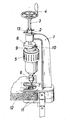
- the drawing shows such a device in perspective.
- the device consists essentially of a tripod 1 designed as a vertical stand, which carries at its upper end a threaded bushing 2 with a vertically arranged thread axis, a threaded spindle 3, which is screw-mounted in the threaded bushing 2 by means of a hand crank 4 arranged at its upper end, and from an engine 5 arranged axially parallel at the lower end of the threaded spindle 3, the drive axis of which is equipped with a chuck 6 for the interchangeable receiving of a stone working tool, for example a grinding wheel 7.
- the connecting device between the threaded spindle 3 and the engine 5 consists of two superimposed plates 8, 9, which are connected to one another by a dovetail guide 10.
- the upper plate 8 is attached to the lower end of the threaded spindle 3, while the counter plate 9 carries the engine 5.
- the dovetail guide 10 the counter plate 9 with the engine 5 can be laterally offset with respect to the threaded spindle 3 with the upper plate 8, so that when the threaded spindle 3 is rotated, the axis of the grinding wheel 7 attached to the engine 5 moves on a circular line.
- Any displacement position that can be reached by the dovetail guide 10 can be fixed by a locking screw, not shown in the drawing.
- Another embodiment, not shown in the drawing, is also possible, in such a way that the two plates are connected to one another by an axle screw instead of a dovetail guide, the upper plate being fastened eccentrically to the threaded spindle and the counter plate carrying the engine.
- the two plates are expediently designed as round disks with the same diameter.
- the drive member of the engine 5 is an electric motor. Instead, a compressed air turbine known per se can also be used.
- the stand 1 is equipped with a plate clamping foot 11 for a connection which can be quickly and easily produced and is connected to a step 12 to be processed.
- a plate clamping foot 11 for a connection which can be quickly and easily produced and is connected to a step 12 to be processed.
- the device which is much lighter than a stone step, can be clamped onto the step in the desired position.
- the device can also be arranged on a table frame, with the steps being pushed under the clamping foot and clamped to it.
- the threaded bushing 2 on the stand 1 is expediently rotatably mounted about the thread axis and lockable in any direction of rotation, a lock nut 13 being arranged on the threaded spindle 3.
- undercuts e.g. Incorporate ring grooves in bores.
- the tool is first brought to the desired depth by rotating the threaded spindle 3 with the threaded sleeve 2 locked and the lock nut 13 is tightened.
- an annular groove is ground into the bore of the stair step by laterally displacing the engine 5 and rotating the threaded spindle 3.
- Conical undercuts of the bores can also be produced in the same way.
- the threaded sleeve 2 can also be arranged fixed on the stand 1, the lock nut 13 being omitted.
Landscapes
- Engineering & Computer Science (AREA)
- Mechanical Engineering (AREA)
- Mining & Mineral Resources (AREA)
- Finish Polishing, Edge Sharpening, And Grinding By Specific Grinding Devices (AREA)
- Grinding And Polishing Of Tertiary Curved Surfaces And Surfaces With Complex Shapes (AREA)
- Grinding Of Cylindrical And Plane Surfaces (AREA)
Applications Claiming Priority (2)
| Application Number | Priority Date | Filing Date | Title |
|---|---|---|---|
| DE19813106612 DE3106612A1 (de) | 1981-02-23 | 1981-02-23 | "geraet zum zurichten von treppenstufen aus natur- und/oder werkstein" |
| DE3106612 | 1981-02-23 |
Publications (2)
| Publication Number | Publication Date |
|---|---|
| EP0058746A2 true EP0058746A2 (fr) | 1982-09-01 |
| EP0058746A3 EP0058746A3 (fr) | 1984-09-05 |
Family
ID=6125499
Family Applications (1)
| Application Number | Title | Priority Date | Filing Date |
|---|---|---|---|
| EP81107379A Withdrawn EP0058746A3 (fr) | 1981-02-23 | 1981-09-17 | Dispositif pour l'usinage des marches d'escalier en pierre |
Country Status (2)
| Country | Link |
|---|---|
| EP (1) | EP0058746A3 (fr) |
| DE (1) | DE3106612A1 (fr) |
Cited By (1)
| Publication number | Priority date | Publication date | Assignee | Title |
|---|---|---|---|---|
| EP0275032A1 (fr) * | 1987-01-14 | 1988-07-20 | Unistrut Europe PLC | Procédé et dispositif pour contre-dépouiller un trou dans un fond d'ancrage |
Families Citing this family (10)
| Publication number | Priority date | Publication date | Assignee | Title |
|---|---|---|---|---|
| DE3505135A1 (de) * | 1985-02-14 | 1986-08-14 | Thumm & Co, 7440 Nürtingen | Vorrichtung zum einschleifen eines gewindes in steinmaterial oder dergleichen |
| DE3829216A1 (de) * | 1988-08-29 | 1990-03-08 | Bosch Gmbh Robert | Werkzeug zum herstellen einer gewindeartigen nut |
| DE4004485A1 (de) * | 1990-02-14 | 1991-08-22 | Fischer Artur Werke Gmbh | Vorrichtung zur herstellung von bohrloechern mit hinterschneidung |
| DE4127745A1 (de) * | 1991-08-22 | 1993-02-25 | Fischer Artur Werke Gmbh | Vorrichtung zur herstellung von bohrloechern mit hinterschneidung |
| SE500139C2 (sv) * | 1992-05-06 | 1994-04-25 | Strukturteknologier I Stockhol | Metod att bearbeta och forma en genomgående öppning i ett fiberarmerat kompositmaterial med ett slipverktyg |
| DE19514379A1 (de) * | 1995-04-19 | 1996-10-24 | Fischer Artur Werke Gmbh | Bohrvorrichtung zur Herstellung von Bohrlöchern mit Hinterschneidung |
| US6007281A (en) * | 1998-04-09 | 1999-12-28 | Novator Ab | Method of producing holes in fiber reinforced composites using a tool with a cutting head having an enlarged diameter and reduced height |
| US6902360B2 (en) * | 2002-02-08 | 2005-06-07 | General Electric Company | Method of cutting a hole in a composite material workpiece |
| WO2011140154A2 (fr) * | 2010-05-03 | 2011-11-10 | National Oilwell Varco, L.P. | Dispositif de coupe sur plate-forme mobile |
| CN108941688B (zh) * | 2018-07-18 | 2020-06-09 | 温州承玥机械设备有限公司 | 一种高精度手持式钻孔机 |
Family Cites Families (5)
| Publication number | Priority date | Publication date | Assignee | Title |
|---|---|---|---|---|
| DE226556C (fr) * | ||||
| GB518297A (en) * | 1938-09-07 | 1940-02-22 | Gerald Charles Harvey | A support for portable drilling machines |
| DE1103803B (de) * | 1957-09-13 | 1961-03-30 | Hans Deckel Dr Ing | Umlaufender Werkzeugtraeger |
| DE7910176U1 (de) * | 1979-04-07 | 1979-08-30 | Hinn, Manfred, 3564 Steffenberg | Treppenstufe |
| ES479883A1 (es) * | 1979-04-24 | 1980-01-16 | Sanchez Velasco Vicente | Aparato para la realizacion de ensanchamientos por fresado en taladros y perforaciones. |
-
1981
- 1981-02-23 DE DE19813106612 patent/DE3106612A1/de active Granted
- 1981-09-17 EP EP81107379A patent/EP0058746A3/fr not_active Withdrawn
Cited By (1)
| Publication number | Priority date | Publication date | Assignee | Title |
|---|---|---|---|---|
| EP0275032A1 (fr) * | 1987-01-14 | 1988-07-20 | Unistrut Europe PLC | Procédé et dispositif pour contre-dépouiller un trou dans un fond d'ancrage |
Also Published As
| Publication number | Publication date |
|---|---|
| DE3106612A1 (de) | 1982-09-02 |
| EP0058746A3 (fr) | 1984-09-05 |
| DE3106612C2 (fr) | 1989-09-07 |
Similar Documents
| Publication | Publication Date | Title |
|---|---|---|
| EP0543046B1 (fr) | Ensemble de vis | |
| DE19624685C1 (de) | Rundstabmesser und insbesondere dafür vorgesehener Messerkopf | |
| EP0142611A1 (fr) | Outil de perçage pour usiner des surfaces de détalonnage dans des perçages préfabriqués | |
| EP0058746A2 (fr) | Dispositif pour l'usinage des marches d'escalier en pierre | |
| DE3150355C2 (de) | Werkzeughaltereinsatz, insbesondere für Bohrstangen | |
| DE7905606U1 (de) | Schnellwechselvorrichtung fuer fraeskopfwerkzeuge | |
| DE8422976U1 (de) | Werkzeughalter mit Radialverstellvorrichtung für ein Werkzeug, insbesondere ein rotierendes Werkzeug | |
| DE2236828B1 (de) | Bohr- oder ausdrehkopf | |
| DE4024059A1 (de) | Handoberfraese | |
| DE3401200C2 (fr) | ||
| DE8104957U1 (de) | "geraet zum zurichten von treppenstufen aus natur- und/oder werkstein" | |
| CH664312A5 (de) | Bohr- und ausdrehwerkzeug. | |
| CH681967A5 (fr) | ||
| DE10319523A1 (de) | Vorrichtung beim nachlaufenden Zweistufen-Auswerfer vom Einbautyp | |
| DE3008008A1 (de) | Spannabhebendes werkzeug | |
| DE10355553B4 (de) | Sensorhalterung | |
| DE3222159A1 (de) | Geraet zum herstellen von hinterschneidungen in bohrungen an treppenstufen oder anderen flaechen aus natur- und/oder werkstein | |
| DE10333017B4 (de) | Kopfbürste | |
| DE9213392U1 (de) | Vorrichtung zur mittelbaren Befestigung von hölzernen Treppenstufen an hölzernen Treppenwangen | |
| DE9319498U1 (de) | Verbindungselement für plattenförmige Werkstücke | |
| DE7415327U (de) | Vorrichtung zur Schnittiefeneinstellung von Hand-Oberfräsen | |
| DE9001062U1 (de) | Vorrichtung zur Bearbeitung einer Natur- oder Kunststeinplatte | |
| DE8117699U1 (de) | "schleifwerkzeug fuer ein geraet zum einschleifen von gewinde oder dergleichen hinterschneidungen in vorgebohrtes stein- oder dergleichen material" | |
| DE9309505U1 (de) | Vorrichtung zur spanabhebenden herstellung von profilen, insbesondere von polygonprofilen | |
| DE2422392B2 (de) | Mit einem elektromagnetischen sockel versehener staender fuer motorisch angetriebene handwerkzeuge |
Legal Events
| Date | Code | Title | Description |
|---|---|---|---|
| PUAI | Public reference made under article 153(3) epc to a published international application that has entered the european phase |
Free format text: ORIGINAL CODE: 0009012 |
|
| AK | Designated contracting states |
Designated state(s): AT BE CH DE FR GB IT SE |
|
| PUAL | Search report despatched |
Free format text: ORIGINAL CODE: 0009013 |
|
| AK | Designated contracting states |
Designated state(s): AT BE CH DE FR GB IT LI SE |
|
| 17P | Request for examination filed |
Effective date: 19850227 |
|
| STAA | Information on the status of an ep patent application or granted ep patent |
Free format text: STATUS: THE APPLICATION IS DEEMED TO BE WITHDRAWN |
|
| 18D | Application deemed to be withdrawn |
Effective date: 19860331 |