EP0058763A1 - Dispositif pour presser du matériau d'enregistrement - Google Patents
Dispositif pour presser du matériau d'enregistrement Download PDFInfo
- Publication number
- EP0058763A1 EP0058763A1 EP81109317A EP81109317A EP0058763A1 EP 0058763 A1 EP0058763 A1 EP 0058763A1 EP 81109317 A EP81109317 A EP 81109317A EP 81109317 A EP81109317 A EP 81109317A EP 0058763 A1 EP0058763 A1 EP 0058763A1
- Authority
- EP
- European Patent Office
- Prior art keywords
- light exit
- exit surface
- recording material
- pressing
- underside
- Prior art date
- Legal status (The legal status is an assumption and is not a legal conclusion. Google has not performed a legal analysis and makes no representation as to the accuracy of the status listed.)
- Withdrawn
Links
- 239000000463 material Substances 0.000 title claims abstract description 13
- 239000004744 fabric Substances 0.000 claims abstract description 9
- 125000006850 spacer group Chemical group 0.000 claims description 2
- 239000011152 fibreglass Substances 0.000 abstract description 13
- 238000010894 electron beam technology Methods 0.000 description 6
- 238000004519 manufacturing process Methods 0.000 description 2
- 229910000831 Steel Inorganic materials 0.000 description 1
- 230000006978 adaptation Effects 0.000 description 1
- 230000006835 compression Effects 0.000 description 1
- 238000007906 compression Methods 0.000 description 1
- 230000007547 defect Effects 0.000 description 1
- 239000007788 liquid Substances 0.000 description 1
- 239000013307 optical fiber Substances 0.000 description 1
- 239000004576 sand Substances 0.000 description 1
- 239000010959 steel Substances 0.000 description 1
Images
Classifications
-
- G—PHYSICS
- G03—PHOTOGRAPHY; CINEMATOGRAPHY; ANALOGOUS TECHNIQUES USING WAVES OTHER THAN OPTICAL WAVES; ELECTROGRAPHY; HOLOGRAPHY
- G03B—APPARATUS OR ARRANGEMENTS FOR TAKING PHOTOGRAPHS OR FOR PROJECTING OR VIEWING THEM; APPARATUS OR ARRANGEMENTS EMPLOYING ANALOGOUS TECHNIQUES USING WAVES OTHER THAN OPTICAL WAVES; ACCESSORIES THEREFOR
- G03B27/00—Photographic printing apparatus
- G03B27/02—Exposure apparatus for contact printing
- G03B27/14—Details
- G03B27/18—Maintaining or producing contact pressure between original and light-sensitive material
-
- G—PHYSICS
- G01—MEASURING; TESTING
- G01D—MEASURING NOT SPECIALLY ADAPTED FOR A SPECIFIC VARIABLE; ARRANGEMENTS FOR MEASURING TWO OR MORE VARIABLES NOT COVERED IN A SINGLE OTHER SUBCLASS; TARIFF METERING APPARATUS; MEASURING OR TESTING NOT OTHERWISE PROVIDED FOR
- G01D15/00—Component parts of recorders for measuring arrangements not specially adapted for a specific variable
- G01D15/14—Optical recording elements; Recording elements using X-or nuclear radiation
Definitions
- the invention relates to a device for pressing recording material to the light exit surface of a recording member in a reproduction apparatus, for. B. in an electronic light setting device.
- An electronic light setting device uses an electron steel tube to produce light sets from digitally stored characters.
- the characters retrieved from the memory are recorded point by line and line by line on the fluorescent screen of the electron beam tube by light-dark control of the electron beam, and the screen images are imaged and exposed on a recording medium in the form of film or photo paper by means of a writing lens, the recording medium being continuous or gradually moved past the fluorescent screen.
- the writing lenses are expensive, they will be cheaper Light setting devices used electron beam tubes, the front plates of which are made of fiberglass (fiberglass plate).
- the recording medium to be exposed moves over the light exit surface of the fiberglass plate and the screen image is transferred to the recording medium via the fiberglass plate.
- a mechanical pressure device ensures that the recording medium is properly positioned on the light exit surface of the fiberglass plate.
- the invention specified in claim 1 is therefore based on the object of specifying a device for pressing recording material onto the light exit surface of a recording element, which adapts individually to the different curvatures or curvatures of the optical fiber plate.
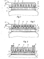
- a fiberglass plate 3 is attached to the fluorescent screen 1 of an electron beam tube 2 as the recording element.
- a recording medium 4 in the form of a film or photo paper moves in the direction of an arrow 5 over the light exit surface 6 of the Fiberglass plate 3 away.
- the light exit surface 6 may be curved due to manufacturing defects (not shown).
- the pressure device consists of a support plate 8 which can be rotated about an axis 7 and which on the underside 9 facing the light exit surface 6 has a plurality of closely spaced cavities 10, z. B. in the form of blind holes. In the cavities 10 there are easily displaceable bodies 11 which can be pressed onto the movable recording medium 4.
- the bodies 11 are pressure weights which, by their weight, press onto the recording medium 4 or onto the light exit surface 6.
- a fabric 12, e.g. B. a velvet cloth or a felt cloth is loosely stretched over the bottom 9 of the support surface 8 and glued to the sides with the support plate 8.
- the velvet or felt cloth is yielding and easily deformable, as a result of which it adapts well to the curvatures of the light exit surface 6 and distributes the pressure of the pressure weights evenly over the light exit surface 6.
- the velvet or felt cloth also has good sliding properties, so that the pressure is applied without damaging the sensitive recording material 4.
- the velvet or felt cloth also ensures that the pressure weights do not fall out of the carrier plate 8.
- Figure 2 shows a second embodiment of the pressure device also in a cross-sectional view.
- the pressure of the bodies 11 on the recording material 4 is preferably achieved by compression springs 13 which are supported on the carrier plate 8.
- FIG. 3 shows a cross section through the pressure device perpendicular to the direction of passage of the recording medium 4.
- the support plate 8 has adjustable spacers 14, e.g. B. screws, which are attached to the side of the recording medium 4 and 6 are supported on the light exit surface. It is thereby achieved that the weight of the carrier plate 8 has no influence on the pressure of the recording medium, but that this is determined exclusively by the body 11.
- the carrier plate 8 thus only serves to guide the bodies 11 in the cavities 10.
- a flat bag could also be used, which is filled with sand or a liquid, for example.
Landscapes
- Physics & Mathematics (AREA)
- General Physics & Mathematics (AREA)
- Electronic Switches (AREA)
Applications Claiming Priority (2)
| Application Number | Priority Date | Filing Date | Title |
|---|---|---|---|
| DE3106916 | 1981-02-25 | ||
| DE3106916 | 1981-02-25 |
Publications (1)
| Publication Number | Publication Date |
|---|---|
| EP0058763A1 true EP0058763A1 (fr) | 1982-09-01 |
Family
ID=6125648
Family Applications (1)
| Application Number | Title | Priority Date | Filing Date |
|---|---|---|---|
| EP81109317A Withdrawn EP0058763A1 (fr) | 1981-02-25 | 1981-10-30 | Dispositif pour presser du matériau d'enregistrement |
Country Status (1)
| Country | Link |
|---|---|
| EP (1) | EP0058763A1 (fr) |
Cited By (2)
| Publication number | Priority date | Publication date | Assignee | Title |
|---|---|---|---|---|
| GB2130387A (en) * | 1982-09-30 | 1984-05-31 | Fuji Photo Film Co Ltd | Film supporting apparatus for cameras |
| DE4129072A1 (de) * | 1991-05-29 | 1992-12-03 | Theimer Siegfried Grafische | Vorrichtung zur durchlaufbelichtung von kopierpartnern |
Citations (5)
| Publication number | Priority date | Publication date | Assignee | Title |
|---|---|---|---|---|
| DE1189851B (de) * | 1963-03-14 | 1965-03-25 | Zindler Lumoprint Kg | Fotografisches Bilduebertragungsverfahren zur Herstellung einer Abbildung und Vorrichtung zur Durchfuehrung dieses Verfahrens |
| FR2221282A1 (fr) * | 1973-03-15 | 1974-10-11 | Ibm | |
| US3867031A (en) * | 1974-02-07 | 1975-02-18 | Scott Paper Co | Method and apparatus for assuring contact between thin sheets of material |
| DE2802423A1 (de) * | 1978-01-20 | 1979-07-26 | Horst Beulich | Andruckelement fuer filmmaterial |
| US4177469A (en) * | 1977-12-08 | 1979-12-04 | Honeywell Inc. | Recorder with electrically conductive paper |
-
1981
- 1981-10-30 EP EP81109317A patent/EP0058763A1/fr not_active Withdrawn
Patent Citations (6)
| Publication number | Priority date | Publication date | Assignee | Title |
|---|---|---|---|---|
| DE1189851B (de) * | 1963-03-14 | 1965-03-25 | Zindler Lumoprint Kg | Fotografisches Bilduebertragungsverfahren zur Herstellung einer Abbildung und Vorrichtung zur Durchfuehrung dieses Verfahrens |
| US3551049A (en) * | 1963-03-14 | 1970-12-29 | Lumoprint Zindler Kg | Photographic method for producing a copy and apparatus for carrying out this method |
| FR2221282A1 (fr) * | 1973-03-15 | 1974-10-11 | Ibm | |
| US3867031A (en) * | 1974-02-07 | 1975-02-18 | Scott Paper Co | Method and apparatus for assuring contact between thin sheets of material |
| US4177469A (en) * | 1977-12-08 | 1979-12-04 | Honeywell Inc. | Recorder with electrically conductive paper |
| DE2802423A1 (de) * | 1978-01-20 | 1979-07-26 | Horst Beulich | Andruckelement fuer filmmaterial |
Cited By (4)
| Publication number | Priority date | Publication date | Assignee | Title |
|---|---|---|---|---|
| GB2130387A (en) * | 1982-09-30 | 1984-05-31 | Fuji Photo Film Co Ltd | Film supporting apparatus for cameras |
| DE4129072A1 (de) * | 1991-05-29 | 1992-12-03 | Theimer Siegfried Grafische | Vorrichtung zur durchlaufbelichtung von kopierpartnern |
| WO1992022011A1 (fr) * | 1991-05-29 | 1992-12-10 | Siegfried Theimer Grafische Geräte GmbH | Dispositif d'eclairage en continu de partenaires de reproduction |
| US5359390A (en) * | 1991-05-29 | 1994-10-25 | Siegfried Theimer Grafische Geraete Gmbh | Apparatus for transmissive exposure of copy pairs |
Similar Documents
| Publication | Publication Date | Title |
|---|---|---|
| DE69614758T2 (de) | Verfahren und Vorrichtung zum Aufzeichnen steroeskopischer Bilder auf vorbeschichtetem Linsenrastermaterial | |
| DE4419521A1 (de) | Ausrichtverfahren und -Vorrichtung für einen Belichtungsprozeß | |
| DE2428419A1 (de) | Zusatzeinrichtung fuer eine kamera | |
| DE2406827B2 (de) | Vorrichtung zum schnellen und praezisen einstellen eines ebenen traegers bezueglich eines beweglichen tisches | |
| DE2927375A1 (de) | Verfahren und geraet zum handhaben und transportieren von bildaufnehmenden medien | |
| DE2717000C2 (fr) | ||
| DE19804313C2 (de) | Stereobildrahmensystem | |
| DE2709614C2 (de) | Belichtungsvorrichtung zur Herstellung eines Bildschirms einer Farbbildröhre | |
| DE3615780C2 (fr) | ||
| DE2462774C2 (de) | Vorrichtung zum photographischen Herstellen von Farbkorrektur-Filmmasken | |
| CH686203A5 (de) | Verfahren zum Erzeugen von Papierbildern. | |
| DE8105175U1 (de) | Vorrichtung zum andruecken von aufzeichnungsmaterial | |
| DE2028938A1 (en) | 3-d images - using polyacrylic cylinder lens plate | |
| CH654423A5 (de) | Fotografisches kopiergeraet. | |
| DE69017054T2 (de) | Kompakter Lichtkollimator für einen Kontaktkopierer mit beweglicher Lichtquelle. | |
| DE2226144C3 (de) | Elektrof otografisches Kopiergerät | |
| DE3422149A1 (de) | Verfahren mit selbsttaetiger scharfeinstellung und vorrichtung zur herstellung von diaabzuegen | |
| DE69006856T2 (de) | Kompaktes kontaktkopiergerät mit transparenter, flexibler abdeckung. | |
| DE682948C (de) | Vorrichtung zum photomechanischen Kopieren von Mustern auf Druckwalzen | |
| DE69017476T2 (de) | Kontaktkopiergerät und verfahren zur belichtung von sensibilisierten graphischen filmen und papieren. | |
| DE959611C (de) | Filmfuehrung an photographischen Kameras mit Aufnahme- und damit gekuppelter Sucherkammer | |
| DE1597787C3 (de) | In eine Reprokamera einsetzbarer Glasraster für reproduktionstechnische Belichtungsvorgänge | |
| DE501540C (de) | Wiedergabevorrichtung mit starrem Gehaeuse | |
| CH402592A (de) | Einrichtung zur Belichtungsregelung in einem optisch-photographischen Kopiergerät | |
| DE8003183U1 (de) | Geraet zur bild-rasterung fuer druckzwecke |
Legal Events
| Date | Code | Title | Description |
|---|---|---|---|
| PUAI | Public reference made under article 153(3) epc to a published international application that has entered the european phase |
Free format text: ORIGINAL CODE: 0009012 |
|
| AK | Designated contracting states |
Designated state(s): AT BE CH FR GB IT NL SE |
|
| STAA | Information on the status of an ep patent application or granted ep patent |
Free format text: STATUS: THE APPLICATION IS DEEMED TO BE WITHDRAWN |
|
| 18D | Application deemed to be withdrawn |
Effective date: 19830805 |
|
| RIN1 | Information on inventor provided before grant (corrected) |
Inventor name: SEGLER, SIEGFRIED Inventor name: PENZA, HANS |