EP0058823B1 - Réservoir de chasse d'eau - Google Patents
Réservoir de chasse d'eau Download PDFInfo
- Publication number
- EP0058823B1 EP0058823B1 EP82100396A EP82100396A EP0058823B1 EP 0058823 B1 EP0058823 B1 EP 0058823B1 EP 82100396 A EP82100396 A EP 82100396A EP 82100396 A EP82100396 A EP 82100396A EP 0058823 B1 EP0058823 B1 EP 0058823B1
- Authority
- EP
- European Patent Office
- Prior art keywords
- water
- closure part
- drain
- float
- toilet flush
- Prior art date
- Legal status (The legal status is an assumption and is not a legal conclusion. Google has not performed a legal analysis and makes no representation as to the accuracy of the status listed.)
- Expired
Links
- XLYOFNOQVPJJNP-UHFFFAOYSA-N water Substances O XLYOFNOQVPJJNP-UHFFFAOYSA-N 0.000 claims abstract description 50
- 230000000694 effects Effects 0.000 description 2
- 239000013505 freshwater Substances 0.000 description 2
- 230000003203 everyday effect Effects 0.000 description 1
- 239000000463 material Substances 0.000 description 1
- 238000009420 retrofitting Methods 0.000 description 1
- 239000010865 sewage Substances 0.000 description 1
- 210000002700 urine Anatomy 0.000 description 1
Images

Classifications
-
- E—FIXED CONSTRUCTIONS
- E03—WATER SUPPLY; SEWERAGE
- E03D—WATER-CLOSETS OR URINALS WITH FLUSHING DEVICES; FLUSHING VALVES THEREFOR
- E03D1/00—Water flushing devices with cisterns ; Setting up a range of flushing devices or water-closets; Combinations of several flushing devices
- E03D1/02—High-level flushing systems
- E03D1/14—Cisterns discharging variable quantities of water also cisterns with bell siphons in combination with flushing valves
- E03D1/142—Cisterns discharging variable quantities of water also cisterns with bell siphons in combination with flushing valves in cisterns with flushing valves
Definitions
- the invention relates to a toilet cistern with a water supply container having an upper cover, a drainage closure part and an actuating device for the drainage closure part which is operatively connected to the drainage closure part, and a float-operated water supply valve, the drainage closure part being loaded by an additional weight or a resilient component which exerts a corresponding force.
- Toilet cisterns of the type mentioned above have proven themselves and work reliably. Toilet cisterns of this type, however, have the disadvantage that they empty their entire water content with a single, brief actuation of the actuating device provided for this purpose. Releasing the actuating device does not interrupt the emptying.
- a urine rinse e.g. the total amount of water in the toilet cistern is not required. Rather, the outflow of approx. 4 l of water is sufficient to get perfect water in the water reservoir of the toilet sink. The water supply in the toilet cistern, which goes beyond this, is uselessly lost when it is completely emptied and would therefore have to be processed into fresh water unnecessarily. This would e.g.
- the invention is therefore based on the object of proposing a toilet cistern of the type described at the outset with which the water consumption can be optimized and thus economically considerable costs can be saved.
- the object is achieved in that the upper cover has a bore in which a vertically arranged guide tube is fastened and in that a rod which projects beyond the guide tube on both sides and whose end protrudes into the water reservoir is supported by a float and the outside projecting end has a stop.
- This is a water level indicator, which allows a particularly simple retrofitting of existing toilet cisterns. If the stop comes to rest on the guide tube, the first partial amount of water has been removed and, if necessary, the actuation of the actuating device can be interrupted and the water drainage can thus be stopped, as a result of which the water consumption can be optimized.
- the stop be slidably and securely arranged on the outwardly projecting end of the rod arranged in the guide tube.
- the water level indicator can be made adjustable for displaying different amounts of water or can be set to different sizes of the water storage containers.
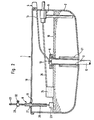
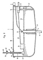
- Fig. Shows a toilet cistern 1, in which the water reservoir 2 is covered by an upper cover 18.
- a water supply valve 5 is arranged in the interior of the water storage container and can be opened or closed in a known and customary manner via a float 24 and an actuating lever 26 connected to the float 24, depending on the water level. If, for example, a water level 10 is reached, the water supply valve 5 is closed. With such Toilet cistern actuated the actuating device 4, the drain closure part 3 is hereby raised via the actuating lever 26 and the water can flow out through the drain pipe 12.
- the drainage closure part 3 is arranged in a guide device 31 and has a fastening part 11 at its upper end.
- Spring-elastic components 7 are fastened to this fastening part 11 and are fastened at their other end to the guide device 31.
- these spring-elastic components 7 are intended to act as tension springs and thus always exert a closing force on the drain closure part. In order to open the drain, this closing force must be overcome by the actuating device 4. However, these are not great forces. With conventional toilet cisterns, a closing force of approx. 120 N is sufficient.
- the upper cover 18 of the toilet cistern has a bore 19 in which a vertically arranged guide tube 20 is fastened by means of a flange 21.
- a rod 22 protrudes on both sides beyond the guide tube.
- a displaceable stop 25 is arranged on the part of the rod 22 which projects upward out of the guide tube and which can be fixed in a selected position by means of the clamping screw 32.
- the other end of the rod 22 is carried by a float 23. It is equally possible that the rod 22 is supported on the float 24. It was then only necessary to choose a different setting of the stop 25. The float 23 can then be omitted.
- a constant closing force acting on the drain closure part 3 can of course also be achieved in that this drain closure part itself is sufficiently heavy.
- a drain valve 9 is provided, which was manufactured from a material of suitable weight. Of course, care must be taken that the function of the drain plug as an overflow pipe is not hindered.
Landscapes
- Health & Medical Sciences (AREA)
- Life Sciences & Earth Sciences (AREA)
- Engineering & Computer Science (AREA)
- Hydrology & Water Resources (AREA)
- Public Health (AREA)
- Water Supply & Treatment (AREA)
- Sanitary Device For Flush Toilet (AREA)
- Vehicle Waterproofing, Decoration, And Sanitation Devices (AREA)
Claims (2)
Priority Applications (1)
| Application Number | Priority Date | Filing Date | Title |
|---|---|---|---|
| AT82100396T ATE9368T1 (de) | 1981-02-24 | 1982-01-21 | Toilettenspuelkasten. |
Applications Claiming Priority (2)
| Application Number | Priority Date | Filing Date | Title |
|---|---|---|---|
| DE19813106764 DE3106764A1 (de) | 1981-02-24 | 1981-02-24 | "toilettenspuelbecken" |
| DE3106764 | 1981-02-24 |
Related Child Applications (1)
| Application Number | Title | Priority Date | Filing Date |
|---|---|---|---|
| EP83110333A Division-Into EP0112986A1 (fr) | 1981-02-24 | 1982-01-21 | Réservoir de chasse d'eau |
Publications (2)
| Publication Number | Publication Date |
|---|---|
| EP0058823A1 EP0058823A1 (fr) | 1982-09-01 |
| EP0058823B1 true EP0058823B1 (fr) | 1984-09-12 |
Family
ID=6125573
Family Applications (2)
| Application Number | Title | Priority Date | Filing Date |
|---|---|---|---|
| EP82100396A Expired EP0058823B1 (fr) | 1981-02-24 | 1982-01-21 | Réservoir de chasse d'eau |
| EP83110333A Withdrawn EP0112986A1 (fr) | 1981-02-24 | 1982-01-21 | Réservoir de chasse d'eau |
Family Applications After (1)
| Application Number | Title | Priority Date | Filing Date |
|---|---|---|---|
| EP83110333A Withdrawn EP0112986A1 (fr) | 1981-02-24 | 1982-01-21 | Réservoir de chasse d'eau |
Country Status (4)
| Country | Link |
|---|---|
| US (1) | US4435859A (fr) |
| EP (2) | EP0058823B1 (fr) |
| AT (1) | ATE9368T1 (fr) |
| DE (2) | DE3106764A1 (fr) |
Families Citing this family (6)
| Publication number | Priority date | Publication date | Assignee | Title |
|---|---|---|---|---|
| DE3304428A1 (de) * | 1983-02-09 | 1984-08-09 | Globol-Werk Gmbh, 8858 Neuburg | Dispenser-vorrichtung fuer toiletten-spuelkaesten |
| US5197151A (en) * | 1991-07-01 | 1993-03-30 | Jasper Jr Louis J | Variable volume flushing device for water conservation |
| CN2782792Y (zh) * | 2005-02-21 | 2006-05-24 | 梁福生 | 两级厕所冲水控制器 |
| US8060954B2 (en) * | 2009-02-13 | 2011-11-22 | Antunez Bruce A | Toilet flush actuator device |
| EA018645B1 (ru) * | 2009-06-19 | 2013-09-30 | Алексей Николаевич Варежкин | Клапан для жидкости |
| US10232588B2 (en) | 2014-04-25 | 2019-03-19 | United States Gypsum Company | Siloxane compositions and methods for reducing VOC and siloxane dust |
Family Cites Families (21)
| Publication number | Priority date | Publication date | Assignee | Title |
|---|---|---|---|---|
| US1149494A (en) | 1915-01-21 | 1915-08-10 | William Briggs | Flush-tank. |
| US1475670A (en) | 1921-04-13 | 1923-11-27 | Yorks Julius | Tank valve |
| US1667990A (en) | 1927-01-28 | 1928-05-01 | Rogers Robert | Valve-operating device |
| US2580898A (en) | 1948-03-02 | 1952-01-01 | Alzugaray Alejandro Dumigron | Flushing tank |
| US2655665A (en) * | 1950-10-25 | 1953-10-20 | Agnew John Stewart | Flush control device for water tanks |
| US2947280A (en) * | 1958-01-29 | 1960-08-02 | Fanders Marten | Flush tank water level indicator |
| US3419912A (en) * | 1966-02-14 | 1969-01-07 | Walker Brooks | Toilet tank flush valve |
| US3831204A (en) * | 1973-02-28 | 1974-08-27 | J Cook | Toilet flush apparatus |
| US3936889A (en) * | 1974-08-13 | 1976-02-10 | The Raymond Lee Organization, Inc. | Toilet flush mechanism |
| US3908203A (en) * | 1974-09-06 | 1975-09-30 | Miles J Jackson | Toilet flush system |
| DE7600907U1 (de) * | 1976-01-15 | 1976-05-20 | Zecher, Wilhelm, 5630 Remscheid | Vorrichtung zum entleeren und selbsttaetigen fuellen eines wasserspeichers, insbesondere toilettenspuelkasten |
| DE2735081A1 (de) * | 1977-08-04 | 1979-02-08 | Bernd Jaeger | Spuelkasten fuer aborte mit wasserspuelung |
| DE7727900U1 (de) * | 1977-09-09 | 1978-01-19 | Sippel, August, 3441 Netra | Vorrichtung zum veraendern der abzugebenden wassermenge an toiletten |
| SU682619A1 (ru) * | 1978-02-13 | 1979-08-30 | В. Н. Зеленин | Смывной бак |
| DE7806291U1 (de) * | 1978-03-02 | 1978-10-12 | Seidl, Josef, 8000 Muenchen | Klosett-spuelkasten mit vorrichtung zur spuelung mit verschiedenen wassermengen |
| DE7812684U1 (de) * | 1978-04-26 | 1978-08-31 | Pawelczyk, Dieter, 3000 Hannover | Spuelkasten fuer wc mit ventilverschluss |
| FR2442306A1 (fr) | 1978-11-22 | 1980-06-20 | Renard Michel | Dispositif de dosage en vue de la distribution de quantites variables de liquide a partir d'un reservoir, adaptable aux mecanismes de chasse couramment utilises dans le sanitaire |
| DE2901821A1 (de) * | 1979-01-18 | 1980-07-31 | Roland Moerl | Wasserdosiereinrichtung fuer wc spuelkaesten |
| DE8001733U1 (de) * | 1980-01-24 | 1980-04-24 | Huebner, Rudolf, 8961 Durach | Klosettspuelkasten |
| DE8009314U1 (de) * | 1980-04-03 | 1980-07-17 | Dellagnolo, Hermann, 7406 Moessingen | Verschlussrohrbeschwerer fuer toiletten-spuelautomaten |
| US4293964A (en) | 1980-09-02 | 1981-10-13 | Riedel Rudolph T | Design for flush tank control using non-buoyant flapper valve |
-
1981
- 1981-02-24 DE DE19813106764 patent/DE3106764A1/de not_active Ceased
-
1982
- 1982-01-21 EP EP82100396A patent/EP0058823B1/fr not_active Expired
- 1982-01-21 EP EP83110333A patent/EP0112986A1/fr not_active Withdrawn
- 1982-01-21 AT AT82100396T patent/ATE9368T1/de not_active IP Right Cessation
- 1982-01-21 DE DE8282100396T patent/DE3260671D1/de not_active Expired
- 1982-02-18 US US06/350,026 patent/US4435859A/en not_active Expired - Fee Related
Also Published As
| Publication number | Publication date |
|---|---|
| EP0112986A1 (fr) | 1984-07-11 |
| ATE9368T1 (de) | 1984-09-15 |
| US4435859A (en) | 1984-03-13 |
| DE3260671D1 (en) | 1984-10-18 |
| EP0058823A1 (fr) | 1982-09-01 |
| DE3106764A1 (de) | 1982-09-09 |
Similar Documents
| Publication | Publication Date | Title |
|---|---|---|
| CH663045A5 (de) | Ablaufgarnitur fuer einen spuelkasten. | |
| EP0058823B1 (fr) | Réservoir de chasse d'eau | |
| DE2520760A1 (de) | Ablaufventil fuer spuelkasten | |
| DE3435778C2 (de) | Hydrant, insbesondere Unterflurhydrant | |
| DE2751468C2 (de) | Rückflußverhinderer | |
| DE3838070A1 (de) | Leichtfluessigkeitsabscheider | |
| DE1773767A1 (de) | Verteilerkasten,insbesondere zur Aufnahme einer Fluessigkeit,die auf einer Giesstrommel zu Baendern oder Boegen vergossen wird | |
| DE2612884B2 (de) | Absperrventil | |
| DE2809825B1 (de) | Rueckstauverschluss fuer Abwasserleitungen | |
| DE8105070U1 (de) | "toilettenspuelbecken" | |
| EP0512157B1 (fr) | Séparateur | |
| DE29604004U1 (de) | Vorrichtung zum stoßweisen Entleeren eines Flüssigkeitsstauraumes, insbesondere in einem Kanalisationsnetz | |
| DE38029C (de) | Einrichtung zur Regulirung des Flüssigkeitsstandes bei nassen Gasmessern | |
| DE2337853B1 (de) | Rückstau- und Geruchsverschluß für Flüssigkeiten, insbesondere Abwässer | |
| DE379409C (de) | Selbsttaetiger Abfuellapparat mit Saugheberpipette | |
| DE2941629A1 (de) | Betaetigungsvorrichtung an auslaufhahnen von behaeltern | |
| DE102023131709A1 (de) | Trennelement für einen Spülbehälter eines Sanitärausstattungsgegenstandes, Spüleinheit für einen Sanitärausstattungsgegenstand und Sanitärausstattungsgegenstand | |
| CH579685A5 (en) | Toilet flush system dispensing selected water surges - has concentric cylinders and valve discs at two levels with pull knobs | |
| DE19643537C2 (de) | Ablaufarmatur zum dosierten Teil- oder Vollabzug von Flüssigkeiten aus einem drucklosen Behälter | |
| CH209950A (de) | Spülkasten. | |
| EP4556643A1 (fr) | Élément de séparation pour un récipient de rinçage d'un élément d'équipement sanitaire, unité de rinçage pour un élément d'équipement sanitaire et élément d'équipement sanitaire | |
| DE9416078U1 (de) | Wasserversorgungsanlage | |
| DE931039C (de) | Heberspuelkasten, insbesondere fuer Klosettanlagen | |
| DE2701351C2 (de) | Automatische Überfüllsicherungsvorrichtung | |
| DE374109C (de) | Selbsttaetig sich schliessendes Ventil |
Legal Events
| Date | Code | Title | Description |
|---|---|---|---|
| PUAI | Public reference made under article 153(3) epc to a published international application that has entered the european phase |
Free format text: ORIGINAL CODE: 0009012 |
|
| 17P | Request for examination filed |
Effective date: 19820512 |
|
| AK | Designated contracting states |
Designated state(s): AT BE DE FR GB IT LU NL |
|
| ITF | It: translation for a ep patent filed | ||
| GRAA | (expected) grant |
Free format text: ORIGINAL CODE: 0009210 |
|
| AK | Designated contracting states |
Designated state(s): AT BE DE FR GB IT LU NL |
|
| REF | Corresponds to: |
Ref document number: 9368 Country of ref document: AT Date of ref document: 19840915 Kind code of ref document: T |
|
| REF | Corresponds to: |
Ref document number: 3260671 Country of ref document: DE Date of ref document: 19841018 |
|
| ET | Fr: translation filed | ||
| PG25 | Lapsed in a contracting state [announced via postgrant information from national office to epo] |
Ref country code: AT Effective date: 19850121 |
|
| PG25 | Lapsed in a contracting state [announced via postgrant information from national office to epo] |
Ref country code: LU Free format text: LAPSE BECAUSE OF NON-PAYMENT OF DUE FEES Effective date: 19850131 Ref country code: BE Effective date: 19850131 |
|
| PLBE | No opposition filed within time limit |
Free format text: ORIGINAL CODE: 0009261 |
|
| STAA | Information on the status of an ep patent application or granted ep patent |
Free format text: STATUS: NO OPPOSITION FILED WITHIN TIME LIMIT |
|
| BERE | Be: lapsed |
Owner name: BARNOWSKI REINHARD Effective date: 19850121 |
|
| PG25 | Lapsed in a contracting state [announced via postgrant information from national office to epo] |
Ref country code: NL Effective date: 19850801 |
|
| NLV4 | Nl: lapsed or anulled due to non-payment of the annual fee | ||
| 26N | No opposition filed | ||
| PG25 | Lapsed in a contracting state [announced via postgrant information from national office to epo] |
Ref country code: FR Free format text: LAPSE BECAUSE OF NON-PAYMENT OF DUE FEES Effective date: 19850930 |
|
| REG | Reference to a national code |
Ref country code: FR Ref legal event code: ST |
|
| GBPC | Gb: european patent ceased through non-payment of renewal fee | ||
| PG25 | Lapsed in a contracting state [announced via postgrant information from national office to epo] |
Ref country code: DE Effective date: 19881001 |
|
| PG25 | Lapsed in a contracting state [announced via postgrant information from national office to epo] |
Ref country code: GB Effective date: 19881121 |