EP0058873B1 - Dispositif d'enroulement - Google Patents
Dispositif d'enroulement Download PDFInfo
- Publication number
- EP0058873B1 EP0058873B1 EP82100920A EP82100920A EP0058873B1 EP 0058873 B1 EP0058873 B1 EP 0058873B1 EP 82100920 A EP82100920 A EP 82100920A EP 82100920 A EP82100920 A EP 82100920A EP 0058873 B1 EP0058873 B1 EP 0058873B1
- Authority
- EP
- European Patent Office
- Prior art keywords
- flyer
- wire
- winding
- rotational axis
- roller
- Prior art date
- Legal status (The legal status is an assumption and is not a legal conclusion. Google has not performed a legal analysis and makes no representation as to the accuracy of the status listed.)
- Expired
Links
- 238000004804 winding Methods 0.000 title claims description 59
- 238000010276 construction Methods 0.000 description 4
- 238000004519 manufacturing process Methods 0.000 description 2
- 238000012986 modification Methods 0.000 description 2
- 230000004048 modification Effects 0.000 description 2
- 230000009467 reduction Effects 0.000 description 2
- 230000004075 alteration Effects 0.000 description 1
- 238000007796 conventional method Methods 0.000 description 1
- 230000007423 decrease Effects 0.000 description 1
- 230000008030 elimination Effects 0.000 description 1
- 238000003379 elimination reaction Methods 0.000 description 1
- 238000000034 method Methods 0.000 description 1
Images

Classifications
-
- H—ELECTRICITY
- H02—GENERATION; CONVERSION OR DISTRIBUTION OF ELECTRIC POWER
- H02K—DYNAMO-ELECTRIC MACHINES
- H02K15/00—Processes or apparatus specially adapted for manufacturing, assembling, maintaining or repairing of dynamo-electric machines
- H02K15/04—Processes or apparatus specially adapted for manufacturing, assembling, maintaining or repairing of dynamo-electric machines of windings prior to their mounting into the machines
- H02K15/043—Processes or apparatus specially adapted for manufacturing, assembling, maintaining or repairing of dynamo-electric machines of windings prior to their mounting into the machines winding flat conductive wires or sheets
- H02K15/0431—Concentrated windings
-
- B—PERFORMING OPERATIONS; TRANSPORTING
- B65—CONVEYING; PACKING; STORING; HANDLING THIN OR FILAMENTARY MATERIAL
- B65H—HANDLING THIN OR FILAMENTARY MATERIAL, e.g. SHEETS, WEBS, CABLES
- B65H54/00—Winding, coiling, or depositing filamentary material
- B65H54/02—Winding and traversing material on to reels, bobbins, tubes, or like package cores or formers
- B65H54/28—Traversing devices; Package-shaping arrangements
- B65H54/2896—Flyers
-
- B—PERFORMING OPERATIONS; TRANSPORTING
- B65—CONVEYING; PACKING; STORING; HANDLING THIN OR FILAMENTARY MATERIAL
- B65H—HANDLING THIN OR FILAMENTARY MATERIAL, e.g. SHEETS, WEBS, CABLES
- B65H59/00—Adjusting or controlling tension in filamentary material, e.g. for preventing snarling; Applications of tension indicators
- B65H59/10—Adjusting or controlling tension in filamentary material, e.g. for preventing snarling; Applications of tension indicators by devices acting on running material and not associated with supply or take-up devices
- B65H59/20—Co-operating surfaces mounted for relative movement
- B65H59/26—Co-operating surfaces mounted for relative movement and arranged to deflect material from straight path
-
- B—PERFORMING OPERATIONS; TRANSPORTING
- B65—CONVEYING; PACKING; STORING; HANDLING THIN OR FILAMENTARY MATERIAL
- B65H—HANDLING THIN OR FILAMENTARY MATERIAL, e.g. SHEETS, WEBS, CABLES
- B65H59/00—Adjusting or controlling tension in filamentary material, e.g. for preventing snarling; Applications of tension indicators
- B65H59/10—Adjusting or controlling tension in filamentary material, e.g. for preventing snarling; Applications of tension indicators by devices acting on running material and not associated with supply or take-up devices
- B65H59/36—Floating elements compensating for irregularities in supply or take-up of material
-
- D—TEXTILES; PAPER
- D01—NATURAL OR MAN-MADE THREADS OR FIBRES; SPINNING
- D01H—SPINNING OR TWISTING
- D01H1/00—Spinning or twisting machines in which the product is wound-up continuously
- D01H1/04—Spinning or twisting machines in which the product is wound-up continuously flyer type
-
- D—TEXTILES; PAPER
- D07—ROPES; CABLES OTHER THAN ELECTRIC
- D07B—ROPES OR CABLES IN GENERAL
- D07B3/00—General-purpose machines or apparatus for producing twisted ropes or cables from component strands of the same or different material
- D07B3/08—General-purpose machines or apparatus for producing twisted ropes or cables from component strands of the same or different material in which the take-up reel rotates about the axis of the rope or cable or in which a guide member rotates about the axis of the rope or cable to guide the rope or cable on the take-up reel in fixed position and the supply reels are fixed in position
- D07B3/085—General-purpose machines or apparatus for producing twisted ropes or cables from component strands of the same or different material in which the take-up reel rotates about the axis of the rope or cable or in which a guide member rotates about the axis of the rope or cable to guide the rope or cable on the take-up reel in fixed position and the supply reels are fixed in position in which a guide member rotates about the axis of the rope or cable to guide the rope or cable on the take-up reel in fixed position
-
- H—ELECTRICITY
- H01—ELECTRIC ELEMENTS
- H01F—MAGNETS; INDUCTANCES; TRANSFORMERS; SELECTION OF MATERIALS FOR THEIR MAGNETIC PROPERTIES
- H01F41/00—Apparatus or processes specially adapted for manufacturing or assembling magnets, inductances or transformers; Apparatus or processes specially adapted for manufacturing materials characterised by their magnetic properties
- H01F41/02—Apparatus or processes specially adapted for manufacturing or assembling magnets, inductances or transformers; Apparatus or processes specially adapted for manufacturing materials characterised by their magnetic properties for manufacturing cores, coils, or magnets
- H01F41/04—Apparatus or processes specially adapted for manufacturing or assembling magnets, inductances or transformers; Apparatus or processes specially adapted for manufacturing materials characterised by their magnetic properties for manufacturing cores, coils, or magnets for manufacturing coils
- H01F41/06—Coil winding
- H01F41/082—Devices for guiding or positioning the winding material on the former
- H01F41/088—Devices for guiding or positioning the winding material on the former using revolving flyers
-
- H—ELECTRICITY
- H01—ELECTRIC ELEMENTS
- H01F—MAGNETS; INDUCTANCES; TRANSFORMERS; SELECTION OF MATERIALS FOR THEIR MAGNETIC PROPERTIES
- H01F41/00—Apparatus or processes specially adapted for manufacturing or assembling magnets, inductances or transformers; Apparatus or processes specially adapted for manufacturing materials characterised by their magnetic properties
- H01F41/02—Apparatus or processes specially adapted for manufacturing or assembling magnets, inductances or transformers; Apparatus or processes specially adapted for manufacturing materials characterised by their magnetic properties for manufacturing cores, coils, or magnets
- H01F41/04—Apparatus or processes specially adapted for manufacturing or assembling magnets, inductances or transformers; Apparatus or processes specially adapted for manufacturing materials characterised by their magnetic properties for manufacturing cores, coils, or magnets for manufacturing coils
- H01F41/06—Coil winding
- H01F41/094—Tensioning or braking devices
-
- D—TEXTILES; PAPER
- D07—ROPES; CABLES OTHER THAN ELECTRIC
- D07B—ROPES OR CABLES IN GENERAL
- D07B2301/00—Controls
- D07B2301/25—System input signals, e.g. set points
- D07B2301/258—Tensile stress
Definitions
- the present invention relates to a winding apparatus for winding wires and the like, comprising a flyer member having a wire passage for passing the wire therethrough and driven for rotation around a winding form for winding the wire onto said winding form, and a roller member.
- US-A-3 762 016 An apparatus of this kind is shown in US-A-3 762 016.
- This specification discloses a device for winding and taping a coil, thereby using an apparatus arranged so that a wire fed from a rotating flyer is wound around a bifurcated coil support unrotatably coupled to a power driven shaft.
- Such an apparatus may be particularly employed as a part of a manufacturing arrangement, for example of coils for electric rotary machines, etc.
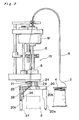
- FIG. 1 showing a conventional winding apparatus, constructions and functions of a flyer and a tension applying device incorporated therein will be described hereinbelow.
- the winding apparatus generally includes the tension applying device T for adjusting a tension of a wire 3 wound on a bobbin 4 and passed through said device T, and a wire passage 5 in the form of a tube for leading the wire 3 from the tension applying device T towards the flyer 1 through a main body 15 of the winding apparatus.
- the flyer 1 is provided with guide rollers 12 and 13 incorporated therein for further guiding the wire 3 into a nozzle portion 14 formed at a distal end of one of a pair of flyer arms 1a extending downwardly from opposite end portions of a flyer base 1b, with said flyer 1 being arranged to be rotated around a winding form or winding frame 2 by a shaft S extending from a motor M to the flyer base 1b through the main body 15 of the winding apparatus and a boss portion B as shown for winding the wire 3 fed out through the nozzle portion 14 onto the winding form 2.
- the tension applying device T further includes guide members 7, 10 and 11 accommodated in a housing Ta in spaced relation from each other.
- Each of the guide members 7, 10 and 11 has an opening for passing the wire 3 therethrough, while the guide member 7 supported on a base 9 and the guide member 10 are each formed with another sets of openings provided to surround the wire passing openings thereof for passing therethrough a tension applying thread 6 which is twisted together between the members 7 and 10 for imparting a tension to the wire 3 in a manner as described later.
- the wire 3 paid out from the bobbin 4 is led through the guide members 11, 10 and 7 and the twisted portion of the thread 6, and further, the wire passage 5, and then, guided by the rollers 12 and 13 so as to be fed out through the nozzle portion 14 and wound onto the winding form 2 as the flyer 1 rotates.
- an essential object of the present invention is to provide a winding apparatus for electric wires, etc., which is capable of applying a proper tension to the wire and the like to be wound in an efficient manner, with substantial elimination of disadvantages inherent in the conventional apparatuses of this kind.
- Another important object of the present invention is to provide a winding apparatus of the above described type which is simple in construction and accurate in functioning at high reliability, and can be readily manufactured at low cost.
- a winding apparatus for winding wires and the like which includes a flyer member having a passage for passing the wire therethrough and driven for rotation around a winding form for winding the wire onto the winding form, a roller member movably mounted on the flyer member for movement in approximately radial direction from the rotational axis of the flyer member so as to depress the wire disposed approximately along a direction parallel to the rotational axis of the flyer member, by a centrifugal force during rotation of the flyer member, and biasing means for urging the roller member towards the rotational axis of the flyer member against the centrifugal force, so that the tension for the wire may be increased during high speed rotation of the flyer member.
- an improved winding apparatus for winding electric wires and the like has been advantageously presented through simple construction and at high reliability for efficient winding operations.
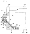
- Fig. 2 a winding apparatus for electric wires and the like according to one preferred embodiment of the present invention, in which the tension applying device T described as employed in the conventional winding apparatus of Fig. 1 is dispensed with, and an improved tension applying arrangement is mainly incorporated into a flyer portion 20 of the apparatus in a manner as described hereinbelow.
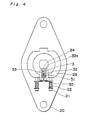
- the flyer portion 20 generally includes a flyer base 20b, a pair of flyer arms 20a and 20c extending downwardly (i.e. laterally towards the right in Fig. 3) from opposite ends of the flyer base 20b, a boss portion 29 secured at an approximately central portion of the base 20b for receiving the shaft S connected to the motor M for rotating the flyer 20 as described with reference to Fig. 1, bolts 21 respectively threaded into the boss portion 29 (Fig.
- the tension applying device T described as employed in the conventional apparatus of Fig. 1 is replaced by the improved tension applying arrangement which is constituted by the roller 24, biasing members 22, bolts 21, a bracket 30, a pin 31 and a slider 32. More specifically, the bolts 21 are respectively threaded into the boss portion 29 through openings (not shown) formed in the bracket 30, while the biasing members 22 in the form of coil springs are disposed between the bracket 30 and the head portions of the bolts 21 (Fig. 4) for limiting the movement of the bracket 30 in the direction of the arrow P in Fig. 3 against the centrifugal force during rotation of the flyer 20.
- the bracket 30 is mounted on the slider 32 by a pin 31, and the roller 24 is rotatably mounted in a groove 32a formed in the slider 32 through a rod 33. Consequently, the roller 24 may be regarded as movably supported in a direction approximately perpendicular to the longitudinal direction of the wire 3 as indicated by the arrows Y in Fig. 3.
- the wire 3 which is fed from the bobbin 4 via the wire passage 5 extending through the main body 15 of the winding apparatus passes through the guide 23, outer peripheries of the rollers 24 and 25, wire passage 28, and outer periphery of the roller 26, and is fed outside the flyer 20 through the nozzle portion 27.
- the tension applying device of the present invention as described in the foregoing is arranged to apply the tension to the wire 3 by the amount of detouring of the wire 3 by the roller 24.
- the slider 32 is moved so that the centrifugal force exerted on the slider 32, rod 33, roller 24, pin 31 and bracket 30, the force applied by the wire 3 to push back the roller 24, and the force exerted by the biasing members 22, are balanced in their sum. More specifically, when the tension for the wire 3 tends to increase upon rapid increase of the discharge amount of the wire 3, the roller 24 moves in the direction indicated by the arrow Q in Fig. 3 for supressing the increase of tension. On the contrary, when the amount of discharge of the wire 3 decreases, the roller 24 moves in the direction indicated by the arrow P in Fig. 3 for supressing the tension, and thus, the tension to be applied to the wire 3 is maintained approximately constant.
- the tension required for winding the wire 3 onto the winding form 2 is increased as the number of revolutions of the flyer 20 becomes larger, the centrifugal force exerted onto the slider 32, rod 33, roller 24, pin 31 and bracket 30, is increased with the increase in the number of revolutions of the flyer 20, with the roller 24 moving in the direction of the arrow P against the urging force by the biasing members 22, and thus, the tension applied to the wire 3 is increased for balancing.
- the tension is applied to the wire within the flyer, with the distance up to the winding form being extremely short as compared with that in the conventional tension applying devices, the elongation of the wire may be extremely reduced, while owing to the automatic increase of the tension, with the increase of the number of revolutions of the flyer, it has been made possible to provide the optimum tension at all times.
Landscapes
- Engineering & Computer Science (AREA)
- Power Engineering (AREA)
- Manufacturing & Machinery (AREA)
- Mechanical Engineering (AREA)
- Textile Engineering (AREA)
- Coil Winding Methods And Apparatuses (AREA)
- Manufacture Of Motors, Generators (AREA)
Claims (5)
Applications Claiming Priority (2)
| Application Number | Priority Date | Filing Date | Title |
|---|---|---|---|
| JP56024110A JPS6052657B2 (ja) | 1981-02-19 | 1981-02-19 | 巻回装置 |
| JP24110/81 | 1981-02-19 |
Publications (2)
| Publication Number | Publication Date |
|---|---|
| EP0058873A1 EP0058873A1 (fr) | 1982-09-01 |
| EP0058873B1 true EP0058873B1 (fr) | 1985-06-26 |
Family
ID=12129191
Family Applications (1)
| Application Number | Title | Priority Date | Filing Date |
|---|---|---|---|
| EP82100920A Expired EP0058873B1 (fr) | 1981-02-19 | 1982-02-09 | Dispositif d'enroulement |
Country Status (4)
| Country | Link |
|---|---|
| US (1) | US4434945A (fr) |
| EP (1) | EP0058873B1 (fr) |
| JP (1) | JPS6052657B2 (fr) |
| DE (1) | DE3264355D1 (fr) |
Cited By (1)
| Publication number | Priority date | Publication date | Assignee | Title |
|---|---|---|---|---|
| CN110168681A (zh) * | 2017-05-31 | 2019-08-23 | 小田原机械工程株式会社 | 喷嘴绕转装置以及卷线机 |
Families Citing this family (13)
| Publication number | Priority date | Publication date | Assignee | Title |
|---|---|---|---|---|
| DE3612803A1 (de) * | 1986-04-16 | 1987-10-22 | Bosch Gmbh Robert | Drahtwickelmaschine, insbesondere ankerwickelmaschine |
| US4920738A (en) * | 1987-03-31 | 1990-05-01 | The Boeing Company | Apparatus for winding optical fiber on a bobbin |
| US4901773A (en) * | 1988-10-24 | 1990-02-20 | Kuhlman Corporation | High voltage coil winding machine |
| FR2771721B1 (fr) * | 1997-12-02 | 2000-02-18 | Lucien Vidal | Dispositif pour transporter pneumatiquement un materiau tel que du beton |
| US6223513B1 (en) | 1999-11-24 | 2001-05-01 | Kamatics Corporation | Flyer bow with integral enclosed wire guide |
| US6289661B1 (en) | 1999-12-07 | 2001-09-18 | Kamatics Corporation | Wire guide holder |
| DE10132718A1 (de) * | 2001-07-05 | 2003-02-13 | Abb T & D Tech Ltd | Verfahren zum Bewickeln eines Dreiphasen-Kabeltransformators mit Koaxialkabel und Wickelvorrichtung hierzu |
| DE102007029811B3 (de) * | 2007-06-27 | 2008-07-24 | Sms Meer Gmbh | Drehrohrhaspel zum Ablegen von gewalztem Draht |
| US8936209B1 (en) | 2010-05-21 | 2015-01-20 | Glenn Auld Knierim | Linear media handling system |
| EP3172377B1 (fr) | 2014-07-21 | 2018-09-12 | KEIR Manufacturing, Inc. | Banc à broches aérodynamique |
| WO2017053611A1 (fr) * | 2015-09-22 | 2017-03-30 | Knierim Glenn Auld | Système de manipulation de supports linéaires et dispositifs produits à l'aide de celui-ci |
| US11878892B2 (en) | 2015-09-22 | 2024-01-23 | Infinity Physics, Llc | Linear media handling system and devices produced using the same |
| US12603563B2 (en) | 2021-01-26 | 2026-04-14 | Electric Mayhem, Llc | Superconducting motors and components thereof |
Family Cites Families (8)
| Publication number | Priority date | Publication date | Assignee | Title |
|---|---|---|---|---|
| DD81358A (fr) * | ||||
| US2814925A (en) | 1954-08-17 | 1957-12-03 | Alfred W Vibber | Twisting and plying spindle balloon control |
| US2727353A (en) | 1954-11-09 | 1955-12-20 | Alfred W Vibber | Twisting and plying spindle balloon control |
| US2909341A (en) | 1957-05-27 | 1959-10-20 | Lewis A Kingsley | Wire aligning and tensioning mechanism |
| US3156324A (en) | 1962-12-27 | 1964-11-10 | Earl F Colbert | Speed regulating attachment for tape recorders |
| GB1310521A (en) * | 1969-03-18 | 1973-03-21 | Mackie & Sons Ltd J | Apparatus for winding packages of synthetic plastic tape |
| US3762016A (en) * | 1971-07-19 | 1973-10-02 | Ginga Electric Ind Co Ltd | Method for continuously automatically forming coils and binding each annular coil with a thermally fusable plastic tape |
| DE2316331C2 (de) * | 1973-04-02 | 1975-03-13 | Palitex Project-Company Gmbh, 4150 Krefeld | Doppeldrahtzwirnspindel mit einem vertikal verschwenkbaren Zwirnflügel |
-
1981
- 1981-02-19 JP JP56024110A patent/JPS6052657B2/ja not_active Expired
-
1982
- 1982-02-09 DE DE8282100920T patent/DE3264355D1/de not_active Expired
- 1982-02-09 US US06/347,268 patent/US4434945A/en not_active Expired - Lifetime
- 1982-02-09 EP EP82100920A patent/EP0058873B1/fr not_active Expired
Cited By (1)
| Publication number | Priority date | Publication date | Assignee | Title |
|---|---|---|---|---|
| CN110168681A (zh) * | 2017-05-31 | 2019-08-23 | 小田原机械工程株式会社 | 喷嘴绕转装置以及卷线机 |
Also Published As
| Publication number | Publication date |
|---|---|
| EP0058873A1 (fr) | 1982-09-01 |
| JPS57138847A (en) | 1982-08-27 |
| DE3264355D1 (en) | 1985-08-01 |
| US4434945A (en) | 1984-03-06 |
| JPS6052657B2 (ja) | 1985-11-20 |
Similar Documents
| Publication | Publication Date | Title |
|---|---|---|
| US4434945A (en) | Winding apparatus | |
| CN206711676U (zh) | 一种束丝机的收线装置 | |
| EP0605464A1 (fr) | Distributeur de fil pour machines textiles consommant des fils. | |
| JPS5953953B2 (ja) | 複数の細いフイラメントを束ねる装置 | |
| US3969880A (en) | Machine for manufacturing cables by stranding individual wires | |
| US3381459A (en) | Continuous winder system and method | |
| JPS6147777B2 (fr) | ||
| US4414802A (en) | Apparatus for stranding wire | |
| US4215529A (en) | Cable winding apparatus | |
| US2714282A (en) | Apparatus for nullifying residual twists of cables | |
| CN213728601U (zh) | 一种伸线机入线引导装置 | |
| NO157558B (no) | Tvinnemaskin. | |
| JPS6019666A (ja) | 定張力バネを用いた線の張力調整装置 | |
| EP0223226B1 (fr) | Dispositif de mise en écheveaux de fils | |
| US2484282A (en) | Wire stranding device | |
| US3119572A (en) | Feed rolls | |
| JP2780642B2 (ja) | 線条体巻取機の線条体ガイド | |
| CN224172205U (zh) | 雪尼尔纱线低损伤络筒机 | |
| US4429519A (en) | Forming cable core units | |
| GB2130259A (en) | Skeining apparatus | |
| CN111108238A (zh) | 纱线加捻机 | |
| SU1666434A1 (ru) | Намоточное устройство | |
| US4121410A (en) | Double twisting machine | |
| US4387745A (en) | Apparatus and methods for handling and controlling wire in winding applications | |
| JPS5940413A (ja) | 非同心型テ−プ巻装置 |
Legal Events
| Date | Code | Title | Description |
|---|---|---|---|
| PUAI | Public reference made under article 153(3) epc to a published international application that has entered the european phase |
Free format text: ORIGINAL CODE: 0009012 |
|
| AK | Designated contracting states |
Designated state(s): DE GB |
|
| 17P | Request for examination filed |
Effective date: 19821109 |
|
| GRAA | (expected) grant |
Free format text: ORIGINAL CODE: 0009210 |
|
| AK | Designated contracting states |
Designated state(s): DE GB |
|
| REF | Corresponds to: |
Ref document number: 3264355 Country of ref document: DE Date of ref document: 19850801 |
|
| PLBE | No opposition filed within time limit |
Free format text: ORIGINAL CODE: 0009261 |
|
| STAA | Information on the status of an ep patent application or granted ep patent |
Free format text: STATUS: NO OPPOSITION FILED WITHIN TIME LIMIT |
|
| 26N | No opposition filed | ||
| PGFP | Annual fee paid to national office [announced via postgrant information from national office to epo] |
Ref country code: GB Payment date: 19940201 Year of fee payment: 13 |
|
| PGFP | Annual fee paid to national office [announced via postgrant information from national office to epo] |
Ref country code: DE Payment date: 19940209 Year of fee payment: 13 |
|
| PG25 | Lapsed in a contracting state [announced via postgrant information from national office to epo] |
Ref country code: GB Effective date: 19950209 |
|
| GBPC | Gb: european patent ceased through non-payment of renewal fee |
Effective date: 19950209 |
|
| PG25 | Lapsed in a contracting state [announced via postgrant information from national office to epo] |
Ref country code: DE Effective date: 19951101 |