EP0059029A1 - Vorrichtung zum Herstellen von visuellen Effekten auf den Oberflächen bewegender Materialien - Google Patents
Vorrichtung zum Herstellen von visuellen Effekten auf den Oberflächen bewegender Materialien Download PDFInfo
- Publication number
- EP0059029A1 EP0059029A1 EP82300329A EP82300329A EP0059029A1 EP 0059029 A1 EP0059029 A1 EP 0059029A1 EP 82300329 A EP82300329 A EP 82300329A EP 82300329 A EP82300329 A EP 82300329A EP 0059029 A1 EP0059029 A1 EP 0059029A1
- Authority
- EP
- European Patent Office
- Prior art keywords
- housing
- fluid
- manifold
- compartment
- elongate
- Prior art date
- Legal status (The legal status is an assumption and is not a legal conclusion. Google has not performed a legal analysis and makes no representation as to the accuracy of the status listed.)
- Granted
Links
- 239000000463 material Substances 0.000 title claims abstract description 30
- 230000000694 effects Effects 0.000 title description 11
- 230000000007 visual effect Effects 0.000 title description 7
- 239000012530 fluid Substances 0.000 claims description 119
- 239000000758 substrate Substances 0.000 claims description 39
- 238000001816 cooling Methods 0.000 claims description 8
- 238000012423 maintenance Methods 0.000 claims description 3
- 238000003825 pressing Methods 0.000 claims 1
- 239000004744 fabric Substances 0.000 description 52
- 238000000059 patterning Methods 0.000 description 11
- 239000004753 textile Substances 0.000 description 11
- 230000000903 blocking effect Effects 0.000 description 7
- 229920001169 thermoplastic Polymers 0.000 description 6
- 239000004416 thermosoftening plastic Substances 0.000 description 6
- 238000006073 displacement reaction Methods 0.000 description 5
- 238000005452 bending Methods 0.000 description 4
- 238000012986 modification Methods 0.000 description 4
- 230000004048 modification Effects 0.000 description 4
- 238000013021 overheating Methods 0.000 description 4
- 238000010276 construction Methods 0.000 description 3
- 239000000835 fiber Substances 0.000 description 3
- 238000009827 uniform distribution Methods 0.000 description 3
- 230000000740 bleeding effect Effects 0.000 description 2
- 230000001105 regulatory effect Effects 0.000 description 2
- 238000003466 welding Methods 0.000 description 2
- 206010037660 Pyrexia Diseases 0.000 description 1
- 206010003549 asthenia Diseases 0.000 description 1
- 238000004140 cleaning Methods 0.000 description 1
- 238000004891 communication Methods 0.000 description 1
- 238000004590 computer program Methods 0.000 description 1
- 230000008602 contraction Effects 0.000 description 1
- 230000001276 controlling effect Effects 0.000 description 1
- 239000000498 cooling water Substances 0.000 description 1
- 238000013500 data storage Methods 0.000 description 1
- 230000001419 dependent effect Effects 0.000 description 1
- 238000011161 development Methods 0.000 description 1
- 230000018109 developmental process Effects 0.000 description 1
- 238000007599 discharging Methods 0.000 description 1
- 238000009826 distribution Methods 0.000 description 1
- 238000001914 filtration Methods 0.000 description 1
- 239000012467 final product Substances 0.000 description 1
- 238000010438 heat treatment Methods 0.000 description 1
- 230000001788 irregular Effects 0.000 description 1
- 238000003754 machining Methods 0.000 description 1
- 238000000034 method Methods 0.000 description 1
- 239000002245 particle Substances 0.000 description 1
- 230000000737 periodic effect Effects 0.000 description 1
- 238000007789 sealing Methods 0.000 description 1
- 125000006850 spacer group Chemical group 0.000 description 1
- 229910001220 stainless steel Inorganic materials 0.000 description 1
- 239000010935 stainless steel Substances 0.000 description 1
- 239000012815 thermoplastic material Substances 0.000 description 1
- XLYOFNOQVPJJNP-UHFFFAOYSA-N water Substances O XLYOFNOQVPJJNP-UHFFFAOYSA-N 0.000 description 1
Images


Classifications
-
- D—TEXTILES; PAPER
- D06—TREATMENT OF TEXTILES OR THE LIKE; LAUNDERING; FLEXIBLE MATERIALS NOT OTHERWISE PROVIDED FOR
- D06C—FINISHING, DRESSING, TENTERING OR STRETCHING TEXTILE FABRICS
- D06C23/00—Making patterns or designs on fabrics
Definitions
- This invention relates to improved apparatus for pressurized heated fluid stream treatment of relatively moving materials to provide visual surface effects therein, and more particularly, to improved apparatus for precise selective application of discrete, high temperature, pressurized streams of air or gaseous materials against the surface of a thermally modifiable, relatively moving substrate material, such as a textile fabric containing thermoplastic yarn or fiber components, to thermally modify the same and impart a visual change and/or pattern effect therein.
- a thermally modifiable, relatively moving substrate material such as a textile fabric containing thermoplastic yarn or fiber components
- apparatus for more precisely and accurately controlling and directing high temperature streams of pressurized fluid, such as air, against the surface of a relatively moving substrate material, such as a textile fabric containing thermoplastic yarns, to impart intricate patterns and surface changes thereto.
- pressurized fluid such as air
- Such apparatus includes an elongate pressurized heated air distributing manifold having a narrow elongate air discharge slot extending across the path of fabric movement in close proximity to the fabric surface.
- a shim plate Located within the manifold is a shim plate having a notched edge which resides in the discharge slot to form parallel spaced discharge channels through which the heated pressurized air passes in narrow, precisely defined streams to impinge upon the adjacent surface of the fabric.
- Flow of the individual heated air streams from the channels is controlled by the use of pressurized cool air which is directed by individual cool air supply tubes communicating with each channel to direct cool air into each discharge channel at a generally right angle to its discharge axis to block the passage of heated air therethrough.
- Each cool air tube is provided with an individual valve and the - valves are selectively cut on and off in response to signal information from a pattern source, such as a computer program, to allow the heated air streams to strike the moving fabric in selected areas and impart a pattern thereto by thermal modification of the yarns.
- pressurized air is supplied to the distributing manifold through a bank of individual electric heaters which communicate with the manifold at uniformly spaced locations along its length and are regulated to introduce heated air at the desired temperature along the full length of the manifold.
- the substrate may be damaged by overheating due to higher temperature of the streams striking the substrate or by direct contact of the substrate with the hot manifold.
- the preferred embodiment of the invention comprises improved fluid distributing manifold means for directing discrete streams of pressurized heated fluid, such as hot air, into the surface of a relatively moving substrate, in particular substrate materials containing thermoplastic components, to impart a precise pattern or surface change thereto.
- the manifold means comprises a pair of elongate manifold housings coupled together and defining respective first and second pressurized fluid-receiving compartments. Heated fluid is supplied to the first elongate manifold housing compartment through multiple inlets, uniformly spaced along its length, and the heated fluid passes through the first housing compartment in a particularly directed path generally perpendicular to its length to facilitate uniform distribution and temperature in the fluid along the length of the housing.
- the heated fluid from the first housing .passes into the second elongate housing compartment which is provided with pressurized fluid discharge outlet channels spaced in parallel relation along the length of the housing to direct streams of fluid generally at a right angle into the surface of the substrate material.
- the manifold housings are constructed and arranged so that the flow path of fluid through the first housing is generally at a right angle to the discharge axes of the fluid stream outlets of the second manifold housing.
- the second manifold housing is disposed across the path of movement of the substrate material and has a plurality of heated fluid discharge outlets spaced along the manifold for discharging pressurized streams of heated fluid, such as hot air, into the surface of the substrate across its width to thermally modify and alter the surface appearance of the substrate.
- Discharge of the streams of heated air from the manifold housing outlets is controlled by selectively introducing a pressurized fluid, such as air, having a temperature substantially lower than the tempera- . ture of the heated air, into the discharge channel of each heated air discharge outlet to block the passage of heated air therethrough.
- the pressurized cool air is introduced into each hot air discharge channel at a substantially right angle to its discharge axis by an individual cool air supply line which is provided with a control valve operated in accordance with pattern information to activate and deactivate the flow of pressurized cool air to the heated air discharge channels.
- the bowing or bending effects tend to be directed in a plane generally perpendicular to the plane of the discharge outlets of the heated air streams, and therefore parallel to the surface of the substrate.
- the displacement of the manifold is resolved in a plane so as to minimize any movement of the discharge outlets toward or away from the substrate, eliminating resultant patterning irregularities in the treated substrate caused by such forces.
- the first manifold housing is provided with baffle means, fluid passageways, and filter means to evenly distribute the fluid along the length of the housing and filter the same during its passage through the housing.
- Quick-release clamping means are provided for supportably attaching the second housing to the first housing to permit its quick removal and replacement during pattern changes and maintenance of the apparatus.
- the second housing is provided with a plurality of hot air outlets located between the heated air discharge channels which communicate by passageways with the second manifold housing compartment to allow a continuous bleed off of a small amount of heated air from the second manifold housing compartment.
- This heated bleed off air contacts the.wall portions of the second manifold housing adjacent the heated air discharge channels to heat the same, thus . reducing the aforementioned localized cooling effect and minimizing the time necessary to re-establish a satisfactory.heated air stream in a previously blocked channel, thereby avoiding resultant patterning irregularities in the substrate material resulting therefrom.
- continuous bleed-off of heated air from the second manifold housing during patterning prevents overheating of the heaters and reduces pressure build up of heated air in the manifold housing when the heated air streams are blocked by the cool air.
- Figure 1 shows, diagrammatically, an overall side elevation view of apparatus for pressurized heated fluid stream treatment of a moving substrate material to..impart a pattern or visual change thereto.
- the apparatus includes a main support frame including end frame support members, one of which 10 is illustrated in Figure 1.
- a plurality of substrate guide rolls Suitably rotatably mounted on the end support members of the frame are a plurality of substrate guide rolls which direct an indefinite length substrate material, such as a textile fabric 12, from a fabric supply roll 14, past a pressurized heated fluid treating unit, generally indicated at 16. After treatment, the fabric is collected in continuous manner on a take-up roll 18.
- fabric 12 from supply roll 14 passes over an idler roll 20 and is fed by a pair of driven rolls 22, 24 to a main driven fabric support roll 26 to pass the surface of the fabric closely adjacent the heated fluid discharge outlets of an elongate fluid distributing manifold assembly 30 of treating unit 16.
- the treated fabric 12 thereafter passes over a series of driven guide rolls 32, 34 and an idler roll 36 to take up'roll 18 for collection.
- fluid treating unit 16 includes a source of compressed fluid, such as an air compressor 38, which supplies pressurized air to an elongate air header pipe 40.
- Header pipe 40 communicates by a series of air lines 42 spaced uniformly along its length with a bank of individual electrical heaters indicated generally at 44.
- the heaters 44 are arranged in parallel along the length of manifold assembly 30 and.supply heated pressurized air thereto through short, individual air supply lines, indicated at 46, which communicate with assembly 30 uniformly along its full length.
- Air supply to the fluid distributing manifold assembly is controlled by a master control valve 48, pressure regulator valve 49, and individual precision control valves, such as needle valves 50, located in each heater air supply line 42.
- the heaters are controlled in suitable manner, as by temperature sensing. means located in the outlet lines 46 of each heater, with regulation of air flow and electrical power to each of the heaters to maintain the heated fluid at. a uniform temperature and pressure as it passes into the manifold assembly along its full length.
- the heaters are . employed to heat air exiting the heaters and entering the manifold assembly to a uniform temperature of about 370°C-510°C.
- the heated fluid distributing manifold assembly 30 is disposed across the full width of the path of movement of the fabric and closely adjacent the surface thereof to be treated.
- the length of the manifold assembly may vary, typically in the treatment of textile fabric materials, the length of the manifold assembly may be 1.93 meters or more to accommodate fabrics of up to about 1.8 meters in width.
- the elongate manifold assembly 30 and the bank of heaters 44 are supported at their ends on the end frame support members 10 of the main support frame by support arms 52 which are pivotally attached to end members 10 to permit movement of the assembly 30 and heaters 44 away from the surface of.the fabric 12 and fabric supporting roller 26 during periods when the movement of the fabric through the treating apparatus may be stopped.
- the manifold assembly 30 comprises a first large elongate manifold housing 54 and a second smaller elongate manifold housing 56 secured in fluid tight relationship therewith by a plurality of spaced clamping means, one of which is generally indicated at 58.
- the manifold housings 54, 56 extend across the full width of the fabric 12 adjacent its path of movement.
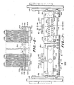
- Clamping means 58 comprises a plurality of manually-operated clamps 60 spaced along the length of the housings: Each clamp includes a first portion 62 fixedly attached, as by welding, to the first manifold housing 54, and a second movable portion 64 pivotally attached to fixed portion 62 by a manually operated handle and linkage mechanism 66. Second portion 64 of clamp 60 includes an adjustable threaded screw and bolt assembly 68 with elongate presser bars 70 which apply pressure to manifold housing 56 through a plurality of spacer blocks 72 which are attached to the surface of housing 56 at spaced locations along its length (Fig. 7).
- first elongate manifold housing 54 is of generally rectangular cross-sectional shape, and includes a pair of spaced plates forming side walls 74, 76 which extend across the full width of the path of fabric movement, and elongate top and bottom wall plates 78, 80 which define a first elongate fluid receiving compartment 81, the ends of which are sealed by end wall plates 82 suitably bolted thereto.
- the side walls 74, 76 of the housing are connected to top wall plate 78 in suitable manner, as by welding, and the bottom wall plate 80 is removably attached to side walls 74, 76 by bolts 84 to permit access to the fluid receiving compartment.
- the plates and walls of the housing 54 are formed of suitable high strength material, such as stainless steel, or the like.
- the manifold housings 54, 56 are constructed and arranged so that the flow path of fluid through the first housing 54 is generally at a right angle to the discharge axes of the fluid stream outlets of the second manifold housing 56.
- the mass comprising, side walls 74, 76 and top and bottom wall plates 78, 80 of first manifold housing 54 is substantially symmetrically arranged on opposing sides of a plane bisecting the first fluid receiving compartment 81 in a direction-parallel to the elongate length of manifold housing 54 and parallel to the predominant direction of fluid flow, i.e., from inlet openings 83 to passageways 86, through the housing compartment 81.
- thermal gradients and the resulting thermally-induced distortions in the first housing 54 also tend to be similarly symmetrical.
- any distortion of the manifold assembly caused by expansion and contraction due to temperature differentials tends to be resolved in a plane generally parallel to the surface of the textile fabric 12 being contacted by the heated fluid streams.
- upper wall plate 78 of manifold housing 54 is of relatively thick construction and is provided with a plurality of fluid flow passageways 86 which are disposed in uniformly spaced relation along the plate in two rows to communicate the first fluid receiving compartment 81 with a central elongate channel 88 in the outer face of plate 78 which. extends between the passageways along the length of the plate.
- the passageways in one row are located in staggered, spaced relation to the passageways in the other row to provide for uniform distribution of pressurized air into the central channel 88 while minimizing strength loss of the elongate plate 78 in the overall manifold assembly.
- baffle plate 92 located in first fluid receiving compartment 81 and attached to the bottom wall plate 80 of the housing 54 by threaded bolts 90 is an elongate channel-shaped baffle plate 92 which extends along the.length of the compartment 81 in overlying relation to wall plate 80 and the spaced, fluid inlet openings 83.
- Baffle plate 92 serves to define a fluid receiving chamber in the compartment 81 having side openings or slots 94 adjacent wall plate 80 to direct the incoming heated air from the bank of heaters in a generally reversing path of flow through compartment 81.
- filter member 96 disposed above channel-shaped baffle plate 92 in compartment 81 between the fluid inlet openings 83 and fluid outlet passageways 86.is an elongate filter member 96 which consists of a preforated, generally J-shaped plate 98 with filter screen 100 disposed thereabout. Filter member 96 extends ' the length of the first fluid receiving compartment 81 and serves to filter foreign particles from the heated pressurized air during its passage therethrough. Access to the compartment 81 by way of removable bottom wall plate 80 permits periodic cleaning and/or replacement of the filter member, and the filter member is maintained in position in the compartment 81 by frictional engagement with the side walls 74, 76 to permit its quick removal from and replacement in the compartment 81.
- second smaller manifold housing 56 comprises first and second opposed elongate wall members 102, 104, each of which has an elongate recess or channel 108 therein.
- Wall members 102, 104 are disposed in spaced, coextensive parallel relation with their channels 108 in facing relation to form upper and lower wall portions of a second fluid receiving compartment 110, in the second manifold housing 56. Ends of the second fluid receiving compartment 110 are closed by end plates 111 (Fig. 7).
- the opposed wall members 102, 104 are maintained in spaced relation by an elongate'front shim plate 112 which has a plurality of parallel, elongate notches 114 (Fig.
- shim plate 112 in one side.edge thereof, and a rear elongate shim plate 116 disposed between the opposed faces of the wall members 102, 104 in fluid tight engagement therewith.
- the notched edge of shim plate 112 is disposed between the first and second wall members along the front elongate edge portions thereof to form, with wall members 102, 104, a plurality of parallel heated fluid discharge outlet channels which direct heated pressurized air from the second fluid receiving compartment 110 in narrow, discrete streams at a substantially right angle into the surface of the moving fabric substrate material 12.
- Dowel pins 117 in second compartment 110 facilitate alignment of shim plate 112 between wall members 102, 104.
- the discharge channels 115 of manifold 56 may be 0.3 mm wide and uniformly spaced on 2.54 mm centers, with 756 discharge channels being located in a row along a 1.93 meter long manifold assembly.
- the discharge outlet channels are preferably maintained between about 0.50 to 0.77 mm from the fabric surface being treated.
- Lower wall member 104-of the second manifold housing 56 is provided with a plurality of fluid inlet openings 118 which communicate with the elongate channel 88 of'the first manifold housing 54 along'its length to receive pressurized heated air from the first manifold housing 54 into the second fluid receiving compartment 110.
- Wall members 102, 104 of the second manifold housing 56 are connected at spaced locations by a plurality of threaded bolts 120, and the second manifold housing 56 is maintained in fluid tight relation with its shim members and with the elongate channel 88 of the first manifold housing 54, by the adjustable clamps 60.
- Guide means comprising a plurality of short guide bars 122 attached to the second manifold housing 56 and received in guide bar openings in brackets 124 attached to the first manifold housing 54, ensure proper alignment of the first and second manifold housings during their attachment by the quick-release clamps 60.
- each of the heated fluid discharge outlet channels 115 of the second manifold housing 56 which direct streams of air into the surface of fabric 12 is provided with a tube 126 which communicates at a right angle to the axis of the discharge channel to introduce pressurized cool air, i.e., air having a temperature substantially below that of the heated air in second fluid receiving compartment 110, into the heated fluid discharge outlet channel to selectively block the flow of heated air through the channel in accordance with pattern control information.
- Air passing . through the tubes 126 may be cooled by a water jacket 127 which is provided with cooling water from a suitable source, not shown.
- pressurized unheated air is supplied to each of the tubes 126 from compressor 38 by way of a master control valve 128, pressure regulator valve 129, air line 130, and unheated air header pipe 132 which is connected by a plurality of 'individual air supply lines 134 to the individual tubes 126.
- Each of the individual cool air supply lines 134 is provided with an individual control valve located in a valve box 136. These individual control valves are operated to open or close in response to signals from a pattern control device, such as a computer 138, to stop the flow of hot air through selected discharge channels 115 during movement of the fabric and thereby produce a desired pattern in the fabric.
- Detailed patterning information for individual patterns may be stored and accessed by means.of any'known data storage medium suitable for use with electronic computers, such as magnetic tape, EPROMs, etc.
- a fluid outlet tube 140 located in the lower wall member 104 between each of the pressurized heated fluid discharge outlet channels 115 is a fluid outlet tube 140.
- Each outlet tube 140 is in continuous communication with the fluid receiving compartment 110 of housing 56 by a passageway 142 formed by an arcuate groove cut into the upper surface of lower wall member 104 between each discharge outlet channel 115 formed by the wall members and shim plate 112.
- Each of the fluid outlet tubes 140 is positioned at a right angle or greater to the axes of discharge of the outlet channels 115, as measured from that portion of the outlet channel closest to the fabric surface, to continuously bleed off a portion of heated pressurized air from the fluid receiving compartment 110 through passageways 142 and to direct the same away from the surface of the moving fabric 12 (Fig. 3).
- the continuous flow of hot air through passageways 142 which extend parallel to channels 115, heats the wall portions of the manifold housing 56 and surface portions of the shim plate 112 between the discharge channels to counteract the cooling of the same when pressurized cool air is introduced into the channels for blocking heated air stream discharge therefrom.
- the amount of air continuously bled off from the fluid receiving compartment 110 through tubes 140 may be varied by use of tubes of varying internal cross-sectional area.
- tubes of varying internal cross-sectional area typically, for patterning textile'fabrics containing thermally deformable components, it has been found that improved results in pattern uniformity have been achieved when the total internal cross-sectional area of the outlet tubes 140 is about one-half or more of the total cross-sectional area of the discharge outlet channels 115 of the manifold housing 56.
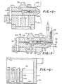
- tubes 140 may be located so as to exit heated air from compartment 110 from any convenient location, such as depicted at 140A of Figure 5.
- Figure 9 shows a modified form of manifold assembly from that shown in Figures 1-8 wherein a second manifold housing 200 without tubes 126 is employed in the manifold assembly to pattern the substrate material.
- the construction and attachment of the manifold housing 200 to the main housing 154 is substantially identical to the fluid distributing manifold housing 56 of Figures 1-8 with the exception of tubes 126 of cooler fluid for blocking discharge of the heated fluid from the manifold channels.
- Housing-200 includes upper and lower elongate wall members 202,.204 with notched shim plate 206 and rear shim plate 208 defining the hot fluid receiving compartment therein.
- the notches of shim plate 206 are spaced at desired locations along the edge of the plate to produce a pattern of continuous stripes along the length of the moving substrate, and stripe pattern changes may be affected by quick' release of the manifold housing 200 from the main manifold housing 154 and replacement of the shim plate 206 therein with shim plates having other notch pattern configurations..
- the sealing surfaces of the upper and lower wall members may be smoothly machined in a single machining operation to ensure fluid tight seal of the housing compartment.
- The' use of two shims of equal thickness to seal the manifold housing compartment also permits the use of notched shim plates of different thicknesses to vary the cross-sectional dimension size of the discharge channels, as desired, without having to provide a different manifold housing construction to accommodate pattern shim plates of different thicknesses.
- an.additional elongate filter medium or screen 210 may be disposed in the second fluid receiving compartment of the manifold assembly to facilitate filtration and distribution of the pressurized heated air prior to its discharge onto the moving substrate material.
- the manifold assembly comprising first and second manifold housings provides a heated pressurized fluid flow path from the bank of heaters which passes through the first manifold housing in a direction generally perpendicular to its elongate length and perpendicular to the axes of discharge of the pressurized fluid streams from the second fluid receiving compartment.
- Such passage provides uniform distribution of the heated fluid, such as air, in the manifold assembly prior to its discharge onto the fabric substrate.
- tempera--ture drops of as much as about 48 0 C occur in the air stream, ignoring the substantial cooling effects induced . by the blocking streams of cooler fluid, when used.
- Such temperature drops cause differential expansion of the first manifold housing which produces a bowing or bending effect along its longitudinal length which is directed by the arrangement and configuration of the manifold assembly in a plane generally parallel to the surface of the fabric substrate and perpendicular to the plane of the discharge axes of the streams from the second manifold housing.
- the displacement of the assembly is resolved in a plane so as to minimize any movement of the discharge outlets of the second housing toward or away from the fabric, eliminating resultant patterning irregularities in the treated fabric caused by such forces.
- Cooling effects induced by the streams of pressurized cooler fluid used to selectively block the heated fluid streams may be compensated by continuously bleeding off heated fluid from the second manifold housing, thereby heating wall portions of the manifold housing, as well as preventing the build up of excess heat and pressure within the second fluid receiving compartment.
Landscapes
- Engineering & Computer Science (AREA)
- Textile Engineering (AREA)
- Treatment Of Fiber Materials (AREA)
Priority Applications (1)
| Application Number | Priority Date | Filing Date | Title |
|---|---|---|---|
| AT82300329T ATE12797T1 (de) | 1981-01-23 | 1982-01-22 | Vorrichtung zum herstellen von visuellen effekten auf den oberflaechen bewegender materialien. |
Applications Claiming Priority (4)
| Application Number | Priority Date | Filing Date | Title |
|---|---|---|---|
| US06/227,838 US4364156A (en) | 1981-01-23 | 1981-01-23 | Apparatus for heated pressurized fluid stream treatment of substrate material |
| US06/227,828 US4393562A (en) | 1981-01-23 | 1981-01-23 | Apparatus for imparting visual surface effects to relatively moving materials |
| US227828 | 1981-01-23 | ||
| US227838 | 1999-01-11 |
Publications (2)
| Publication Number | Publication Date |
|---|---|
| EP0059029A1 true EP0059029A1 (de) | 1982-09-01 |
| EP0059029B1 EP0059029B1 (de) | 1985-04-17 |
Family
ID=26921797
Family Applications (1)
| Application Number | Title | Priority Date | Filing Date |
|---|---|---|---|
| EP19820300329 Expired EP0059029B1 (de) | 1981-01-23 | 1982-01-22 | Vorrichtung zum Herstellen von visuellen Effekten auf den Oberflächen bewegender Materialien |
Country Status (4)
| Country | Link |
|---|---|
| EP (1) | EP0059029B1 (de) |
| DE (1) | DE3263058D1 (de) |
| IE (1) | IE52575B1 (de) |
| MX (1) | MX156073A (de) |
Cited By (3)
| Publication number | Priority date | Publication date | Assignee | Title |
|---|---|---|---|---|
| FR2543588A1 (fr) * | 1983-03-28 | 1984-10-05 | Milliken Res Corp | Procede de formation de motifs a la surface de substrats textiles, et produit obtenu par sa mise en oeuvre |
| EP0121290A1 (de) * | 1983-01-07 | 1984-10-10 | Milliken Research Corporation | Verfahren und Vorrichtung zum thermischen Herstellen von Mustern auf textilen Warenbahnen |
| US7183231B2 (en) | 2001-11-07 | 2007-02-27 | The Procter & Gamble Company | Textured materials and method of manufacturing textured materials |
Citations (3)
| Publication number | Priority date | Publication date | Assignee | Title |
|---|---|---|---|---|
| US3613186A (en) * | 1969-10-07 | 1971-10-19 | Stevens & Co Inc J P | Apparatus for producing sculptured effects on pile fabrics |
| US3635625A (en) * | 1970-01-12 | 1972-01-18 | Phillips Petroleum Co | Apparatus for carving a material sheet |
| GB2065035A (en) * | 1979-12-13 | 1981-06-24 | Milliken Res Corp | Method and apparatus for treatment of substrates to produce visual surface effects |
-
1982
- 1982-01-21 MX MX19108282A patent/MX156073A/es unknown
- 1982-01-21 IE IE12782A patent/IE52575B1/en not_active IP Right Cessation
- 1982-01-22 EP EP19820300329 patent/EP0059029B1/de not_active Expired
- 1982-01-22 DE DE8282300329T patent/DE3263058D1/de not_active Expired
Patent Citations (4)
| Publication number | Priority date | Publication date | Assignee | Title |
|---|---|---|---|---|
| US3613186A (en) * | 1969-10-07 | 1971-10-19 | Stevens & Co Inc J P | Apparatus for producing sculptured effects on pile fabrics |
| US3729784A (en) * | 1969-10-07 | 1973-05-01 | Stevens & Co Inc J P | Process for producing sculptured effects on thermoplastic pile fabrics |
| US3635625A (en) * | 1970-01-12 | 1972-01-18 | Phillips Petroleum Co | Apparatus for carving a material sheet |
| GB2065035A (en) * | 1979-12-13 | 1981-06-24 | Milliken Res Corp | Method and apparatus for treatment of substrates to produce visual surface effects |
Cited By (5)
| Publication number | Priority date | Publication date | Assignee | Title |
|---|---|---|---|---|
| EP0121290A1 (de) * | 1983-01-07 | 1984-10-10 | Milliken Research Corporation | Verfahren und Vorrichtung zum thermischen Herstellen von Mustern auf textilen Warenbahnen |
| FR2543588A1 (fr) * | 1983-03-28 | 1984-10-05 | Milliken Res Corp | Procede de formation de motifs a la surface de substrats textiles, et produit obtenu par sa mise en oeuvre |
| EP0120709A3 (en) * | 1983-03-28 | 1985-05-29 | Milliken Research Corporation | High contrast patterning process and product |
| CH669493GA3 (de) * | 1983-03-28 | 1989-03-31 | ||
| US7183231B2 (en) | 2001-11-07 | 2007-02-27 | The Procter & Gamble Company | Textured materials and method of manufacturing textured materials |
Also Published As
| Publication number | Publication date |
|---|---|
| IE820127L (en) | 1982-07-23 |
| DE3263058D1 (en) | 1985-05-23 |
| MX156073A (es) | 1988-06-29 |
| IE52575B1 (en) | 1987-12-23 |
| EP0059029B1 (de) | 1985-04-17 |
Similar Documents
| Publication | Publication Date | Title |
|---|---|---|
| US4364156A (en) | Apparatus for heated pressurized fluid stream treatment of substrate material | |
| US4393562A (en) | Apparatus for imparting visual surface effects to relatively moving materials | |
| EP0057999B1 (de) | Herstellung von auf verschiedenen Tiefen gemusterten Materialien | |
| US4471514A (en) | Apparatus for imparting visual surface effects to relatively moving materials | |
| US4323760A (en) | Method and apparatus for temperature control of heated fluid in a fluid handling system | |
| US5674581A (en) | Textile fabric having a thermally modified narrow channel to facilitate separation | |
| US5580581A (en) | Meltblowing die with replaceable preset die tip assembly | |
| US4499637A (en) | Method for the production of materials having visual surface effects | |
| US5148583A (en) | Method and apparatus for patterning of substrates | |
| US3324526A (en) | Yarn treating jet | |
| EP0059029B1 (de) | Vorrichtung zum Herstellen von visuellen Effekten auf den Oberflächen bewegender Materialien | |
| GB2132324A (en) | Apparatus for treatment of a web of material by gaseous medium | |
| US4875846A (en) | Spinning apparatus | |
| US4777736A (en) | System for drying web material utilizing removable/adjustable nozzle | |
| KR850001670B1 (ko) | 시각적 표면효과를 가진 물질의 제조방법 | |
| EP0121290B1 (de) | Verfahren und Vorrichtung zum thermischen Herstellen von Mustern auf textilen Warenbahnen | |
| US3357224A (en) | Roll cooling | |
| EP0184625B2 (de) | Garnbehandlungsdüse | |
| CA1263818A (en) | Method and system for cooling strip | |
| CA2315822C (en) | Heating system for compressive shrinkage machines | |
| JPH04228672A (ja) | 基板材料への加熱与圧流体の流れ処理の方法および装置 | |
| EP0537395A1 (de) | Verfahren und Vorrichtung zum Entfernen von Material mittels erhitztem Druckflüssigkeitsstrahl | |
| IE50576B1 (en) | Method of raising the pile of a pile fabric | |
| CA2055118A1 (en) | Method and apparatus for removal of substrate material by means of heated pressurized fluid stream |
Legal Events
| Date | Code | Title | Description |
|---|---|---|---|
| PUAI | Public reference made under article 153(3) epc to a published international application that has entered the european phase |
Free format text: ORIGINAL CODE: 0009012 |
|
| AK | Designated contracting states |
Designated state(s): AT BE CH DE FR GB IT LU NL SE |
|
| 17P | Request for examination filed |
Effective date: 19821124 |
|
| ITF | It: translation for a ep patent filed | ||
| GRAA | (expected) grant |
Free format text: ORIGINAL CODE: 0009210 |
|
| AK | Designated contracting states |
Designated state(s): AT BE CH DE FR GB IT LI LU NL SE |
|
| REF | Corresponds to: |
Ref document number: 12797 Country of ref document: AT Date of ref document: 19850515 Kind code of ref document: T |
|
| REF | Corresponds to: |
Ref document number: 3263058 Country of ref document: DE Date of ref document: 19850523 |
|
| ET | Fr: translation filed | ||
| PLBE | No opposition filed within time limit |
Free format text: ORIGINAL CODE: 0009261 |
|
| STAA | Information on the status of an ep patent application or granted ep patent |
Free format text: STATUS: NO OPPOSITION FILED WITHIN TIME LIMIT |
|
| 26N | No opposition filed | ||
| ITTA | It: last paid annual fee | ||
| EPTA | Lu: last paid annual fee | ||
| EAL | Se: european patent in force in sweden |
Ref document number: 82300329.8 |
|
| PGFP | Annual fee paid to national office [announced via postgrant information from national office to epo] |
Ref country code: LU Payment date: 20001201 Year of fee payment: 20 |
|
| PGFP | Annual fee paid to national office [announced via postgrant information from national office to epo] |
Ref country code: AT Payment date: 20001215 Year of fee payment: 20 |
|
| PGFP | Annual fee paid to national office [announced via postgrant information from national office to epo] |
Ref country code: FR Payment date: 20001218 Year of fee payment: 20 |
|
| PGFP | Annual fee paid to national office [announced via postgrant information from national office to epo] |
Ref country code: CH Payment date: 20001220 Year of fee payment: 20 |
|
| PGFP | Annual fee paid to national office [announced via postgrant information from national office to epo] |
Ref country code: SE Payment date: 20001227 Year of fee payment: 20 |
|
| PGFP | Annual fee paid to national office [announced via postgrant information from national office to epo] |
Ref country code: GB Payment date: 20001228 Year of fee payment: 20 |
|
| PGFP | Annual fee paid to national office [announced via postgrant information from national office to epo] |
Ref country code: NL Payment date: 20010109 Year of fee payment: 20 |
|
| PGFP | Annual fee paid to national office [announced via postgrant information from national office to epo] |
Ref country code: BE Payment date: 20010111 Year of fee payment: 20 |
|
| PGFP | Annual fee paid to national office [announced via postgrant information from national office to epo] |
Ref country code: DE Payment date: 20010330 Year of fee payment: 20 |
|
| BE20 | Be: patent expired |
Free format text: 20020122 *MILLIKEN RESEARCH CORP. |
|
| REG | Reference to a national code |
Ref country code: GB Ref legal event code: IF02 |
|
| PG25 | Lapsed in a contracting state [announced via postgrant information from national office to epo] |
Ref country code: LI Free format text: LAPSE BECAUSE OF EXPIRATION OF PROTECTION Effective date: 20020121 Ref country code: GB Free format text: LAPSE BECAUSE OF EXPIRATION OF PROTECTION Effective date: 20020121 Ref country code: CH Free format text: LAPSE BECAUSE OF EXPIRATION OF PROTECTION Effective date: 20020121 |
|
| PG25 | Lapsed in a contracting state [announced via postgrant information from national office to epo] |
Ref country code: NL Free format text: LAPSE BECAUSE OF EXPIRATION OF PROTECTION Effective date: 20020122 Ref country code: LU Free format text: LAPSE BECAUSE OF EXPIRATION OF PROTECTION Effective date: 20020122 Ref country code: AT Free format text: LAPSE BECAUSE OF EXPIRATION OF PROTECTION Effective date: 20020122 |
|
| PG25 | Lapsed in a contracting state [announced via postgrant information from national office to epo] |
Ref country code: SE Free format text: LAPSE BECAUSE OF NON-PAYMENT OF DUE FEES Effective date: 20020123 |
|
| REG | Reference to a national code |
Ref country code: GB Ref legal event code: PE20 Effective date: 20020121 |
|
| REG | Reference to a national code |
Ref country code: CH Ref legal event code: PL |
|
| EUG | Se: european patent has lapsed |
Ref document number: 82300329.8 |
|
| NLV7 | Nl: ceased due to reaching the maximum lifetime of a patent |