EP0059112B1 - Système de soupape d'arrêt et de décharge - Google Patents
Système de soupape d'arrêt et de décharge Download PDFInfo
- Publication number
- EP0059112B1 EP0059112B1 EP82300956A EP82300956A EP0059112B1 EP 0059112 B1 EP0059112 B1 EP 0059112B1 EP 82300956 A EP82300956 A EP 82300956A EP 82300956 A EP82300956 A EP 82300956A EP 0059112 B1 EP0059112 B1 EP 0059112B1
- Authority
- EP
- European Patent Office
- Prior art keywords
- valve
- chamber
- fluid passage
- drain
- valve system
- Prior art date
- Legal status (The legal status is an assumption and is not a legal conclusion. Google has not performed a legal analysis and makes no representation as to the accuracy of the status listed.)
- Expired
Links
- 239000012530 fluid Substances 0.000 claims abstract description 41
- 239000007921 spray Substances 0.000 claims abstract description 24
- 238000004140 cleaning Methods 0.000 claims abstract description 17
- 238000005507 spraying Methods 0.000 claims abstract description 5
- 238000004891 communication Methods 0.000 claims abstract description 3
- 239000000463 material Substances 0.000 claims description 8
- 235000021056 liquid food Nutrition 0.000 claims description 7
- 235000013405 beer Nutrition 0.000 description 10
- 238000010276 construction Methods 0.000 description 4
- 239000007788 liquid Substances 0.000 description 3
- 238000011109 contamination Methods 0.000 description 2
- 238000004519 manufacturing process Methods 0.000 description 2
- 208000035143 Bacterial infection Diseases 0.000 description 1
- 208000022362 bacterial infectious disease Diseases 0.000 description 1
- 239000011538 cleaning material Substances 0.000 description 1
- 235000013365 dairy product Nutrition 0.000 description 1
- 238000010586 diagram Methods 0.000 description 1
- 235000013305 food Nutrition 0.000 description 1
- 238000009434 installation Methods 0.000 description 1
- 238000002955 isolation Methods 0.000 description 1
- 238000012986 modification Methods 0.000 description 1
- 230000004048 modification Effects 0.000 description 1
- 230000000737 periodic effect Effects 0.000 description 1
- 230000000704 physical effect Effects 0.000 description 1
- 238000007789 sealing Methods 0.000 description 1
Images
Classifications
-
- B—PERFORMING OPERATIONS; TRANSPORTING
- B67—OPENING, CLOSING OR CLEANING BOTTLES, JARS OR SIMILAR CONTAINERS; LIQUID HANDLING
- B67C—CLEANING, FILLING WITH LIQUIDS OR SEMILIQUIDS, OR EMPTYING, OF BOTTLES, JARS, CANS, CASKS, BARRELS, OR SIMILAR CONTAINERS, NOT OTHERWISE PROVIDED FOR; FUNNELS
- B67C3/00—Bottling liquids or semiliquids; Filling jars or cans with liquids or semiliquids using bottling or like apparatus; Filling casks or barrels with liquids or semiliquids
- B67C3/001—Cleaning of filling devices
-
- B—PERFORMING OPERATIONS; TRANSPORTING
- B08—CLEANING
- B08B—CLEANING IN GENERAL; PREVENTION OF FOULING IN GENERAL
- B08B3/00—Cleaning by methods involving the use or presence of liquid or steam
- B08B3/02—Cleaning by the force of jets or sprays
- B08B3/026—Cleaning by making use of hand-held spray guns; Fluid preparations therefor
-
- B—PERFORMING OPERATIONS; TRANSPORTING
- B08—CLEANING
- B08B—CLEANING IN GENERAL; PREVENTION OF FOULING IN GENERAL
- B08B2203/00—Details of cleaning machines or methods involving the use or presence of liquid or steam
- B08B2203/02—Details of machines or methods for cleaning by the force of jets or sprays
- B08B2203/0282—Safety devices
-
- Y—GENERAL TAGGING OF NEW TECHNOLOGICAL DEVELOPMENTS; GENERAL TAGGING OF CROSS-SECTIONAL TECHNOLOGIES SPANNING OVER SEVERAL SECTIONS OF THE IPC; TECHNICAL SUBJECTS COVERED BY FORMER USPC CROSS-REFERENCE ART COLLECTIONS [XRACs] AND DIGESTS
- Y10—TECHNICAL SUBJECTS COVERED BY FORMER USPC
- Y10T—TECHNICAL SUBJECTS COVERED BY FORMER US CLASSIFICATION
- Y10T137/00—Fluid handling
- Y10T137/4238—With cleaner, lubrication added to fluid or liquid sealing at valve interface
- Y10T137/4245—Cleaning or steam sterilizing
- Y10T137/4259—With separate material addition
-
- Y—GENERAL TAGGING OF NEW TECHNOLOGICAL DEVELOPMENTS; GENERAL TAGGING OF CROSS-SECTIONAL TECHNOLOGIES SPANNING OVER SEVERAL SECTIONS OF THE IPC; TECHNICAL SUBJECTS COVERED BY FORMER USPC CROSS-REFERENCE ART COLLECTIONS [XRACs] AND DIGESTS
- Y10—TECHNICAL SUBJECTS COVERED BY FORMER USPC
- Y10T—TECHNICAL SUBJECTS COVERED BY FORMER US CLASSIFICATION
- Y10T137/00—Fluid handling
- Y10T137/8593—Systems
- Y10T137/87096—Valves with separate, correlated, actuators
- Y10T137/87113—Interlocked
Definitions
- This invention relates to block and bleed valve systems suitable for use in complex pipe systems which require periodic internal cleansing.
- valve isolating systems permit satisfactory cleaning of most of the pipework their use involves significant risks insofar as there are normally present dead-spaces in the vicinity of the valves which are not accessible to the cleaning fluid or at least not to the physical action thereof. Also such systems do not provide any protection against leakage of cleaning fluid from one part of the pipework on one side of the valve system to another part on the other side which still contains food material which as a result could become seriously contaminated.
- the present invention provides a double block and bleed valve system comprising a valve body defining a valve chamber between first and second fluid passage openings provided with first and second valve means respectively, and connectable, in use of the system to respective pipe sections, from which said chamber is isolatable in use by closure of said first and second valve means, said chamber having a drain outlet therefrom; and a spray means having an inlet in communication with the exterior of the chamber for connection, in use, with a cleaning fluid supply, and having at least one spray head in said chamber for spraying, in use, interior surfaces of said chamber with cleaning fluid supplied thereto, said drain outlet being disposed remote from said first and second fluid passage openings, and said spray head being formed and arranged for spraying, in use, substantially all the interior surfaces of said chamber when said first and second valve means are in their closed positions, said first and second valve means and chamber being formed and arranged so that said chamber is substantially.
- said drain outlet is provided with a drain valve and said spray means is mounted at a wall of said valve body so as to extend from said spray means inlet through an opening in said wall remote from said first and second fluid passage openings and first and second valve means, to said spray head.
- valve system of the present invention permits thorough and effective cleaning of pipework to either side thereof as well as in its own interior whilst providing good protection against accidental leakage of cleaning material to parts of the system not undergoing cleaning and whilst employing a relatively simple and inexpensive form of construction using more or less readily available components which do not require special manufacture.
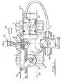
- Figure 1 shows a valve system comprisng a chamber constituted by a Tee-pipe whose crosspiece provides first and second arms terminating in first and second fluid passage openings 6, 7, respectively and whose other member 8 terminates in a drain opening 9.
- the fluid passage openings 6, 7 are provided with respective first and second valve means 10, 11 in the form of conventional butterfly valves provided with rotary drive shafts 12.
- a hydraulic actuator 13 is provided on the second valve 11 for opening and closing the latter and is connected by a simple parallel arm linkage 14 to the first valve 10 for simultaneous operation thereof with the second valve 11.
- the drain opening 9 is also provided with a valve means in the form of a butterfly valve 15 is also provided with an actuator 16. The latter is connected via a hydraulic fluid line 17 to second valve means actuator 13 for simultaneous operation therewith so that as the first and second valves 10, 11 are closed, the drain valve 15 is opened and as the former are opened the latter is closed.
- a spray means 18 in the form of a conduit 19 extending through an opening 20 with a spray head 21 at its free end 22 disposed in the chamber 2 and having an inlet 23 at its other end connected to a cleaning fluid supply 24 via a control valve 25.
- the first and second fluid passage openings 6, 7 are connected via the butterfly valves 10, 11 to respective pipe sections 26, 27 of a pipework circuit 28 (see below) in conventional manner.
- the spray head 21 of the spray means 19 is of the ball type and as may be seen from the drawing is formed and positioned in the chamber so that in use cleaning fluid will be sprayed therefrom over substantially the whole of the interior surface of the chambr 2 including interior walls of the arms 4, 5 member 8, inlet 20, and the respective inwardly directed faces of the butterfly valves 10, 11, 15.
- this arrangement is particularly convenient other forms of spray head could also be used as well as more than one spray head, different spray heads being used for different parts of the chamber 2.
- valve could be used instead of butterfly valves and different forms of actuators without affecting the basic mode of operation of the system which will now-be described with reference to Fig. 2.
- Fig. 2 shows a processing tank 30 with a first beer main 31 connected to one side 32 and a second beer main 33 connected to the base 34 thereof.
- the beer mains are provided with conventional closing valves 35-37 and are also connected in parallel, via respective block and bleed valve systems 38-40 of the invention, to C.I.P. (Cleaning-In-Place) fluid mains 41-43.
- the block and bleed valve systems 38-40 are shown essentially schematically except in the case of the one 38 connected in the first beer main 31, wherein there are schematically indicated the first and second butterfly valves 10, 11, the drain opening 9 provided with its butterfly valve 15, and the (C.I.P.) spray conduit 19.
- the beer main is entirely isolated.from the C.I.P. main with a high degree of security.
- the closing valve 35 between the side 32 of the tank 30 and the block and bleed valve system 38 is closed as is also a corresponding closing valve 44 in the C.I.P. main 41.
- the first and second butterfly valves 10, 11 are opened and C.I.P. fluid is diverted from the C.I.P. main 41 through the first beer main 31 the drain valve 15 being closed at this stage.
- the first and second butterfly valves 10, 11 are both closed and the zone therebetween cleaned by passing C.I.P.
- both the first and second valves 10, 11 remain closed.
- the drain valve 15 is however kept open so that in the event that the sealing at either of the first and second valves 10, 11 should fail any leakage is drained off safely thereby preventing any possible build up of pressure between the first and second valves 10, 11 thereby protecting against the possibility of leakage from one side of the system- across both the first and second valves 10, 11 - to the other side of the system.
- a tundish or other receptacle below the drain outlet 9 to catch any leakage so that any seal failure would be indicated by the presence of liquid in the tundish and thus quickly detected.
- pneumatically operated actuators can be used instead of hydraulically operated ones and indeed may be preferred to the latter.
- other forms of mechanical linkage between the first and second valves could be used in place of the parallel arm linkage 14-for example there could be used a rack and pinion linkage.
- simultaneous operation of the first and second valves could be provided by means of a suitable hydraulic or pneumatic control circuit linking respective actuators associated with each of the first and second valves.
- the block and bleed system of the present invention in contrast to previously known systems it can be simply installed in straight pipe runs and does not require special design of the three dimensional layout of the pipes in the plant in which it is used to provide cross-over points between adjacent pipes to permit installation of the system at such points.
- the present invention provide a valve system which is relatively simple in construction and thus potentially more reliable, as well as being relatively economical to manufacture, it also simplifies and reduces the costs of the overall plant design.
- the block and bleed system of the invention may be used in different ways from that specifically described above.
- it could be installed in line with a beer or other liquid main at one or more points therein for isolation of different sections of the main as required.
- both the first and second valves are kept open for passage of beer therethrough and the drain valve kept closed.
- the first and second valve are closed and the drain valve opened so that if C.I.P. or other fluid is then introduced into the section on one side of the system it is securely prevented from coming into contact with the section on the other side thereby preventing contamination of any beer or other liquid present therein by the C.I.P. fluid.
- the drain or bleed valve is interlocked with the first and second valves so that when the latter are open the former cannot be opened thereby preventing the possibility of accidental loss of fluid during normal fluid flow through the system via said first and second fluid passage openings.
- the present invention provides: a liquid food material handling plant having a complex pipe system including at least one pipe run wherein is connected in line with said pipe run a double block and bleed valve system of the invention, said pipe run having first and second sections extending to either side of said valve system and coupled to said first and second fluid passage openings of said valve system; and a liquid food material handling plant having a complex pipe system including at least one first pipe run for liquid food material and at least one second pipe run for cleaning-in-place fluid wherein is connected across said pipe runs a double block and bleed valve system of the invention, with the first and second fluid passage openings of said valve system connected to respective ones of said first and second pipe runs.
Landscapes
- Lift Valve (AREA)
- Fluid-Pressure Circuits (AREA)
- Control Of The Air-Fuel Ratio Of Carburetors (AREA)
- Multiple-Way Valves (AREA)
- Fluid-Driven Valves (AREA)
- Details Or Accessories Of Spraying Plant Or Apparatus (AREA)
- Spray Control Apparatus (AREA)
Claims (10)
Priority Applications (1)
| Application Number | Priority Date | Filing Date | Title |
|---|---|---|---|
| AT82300956T ATE19683T1 (de) | 1981-02-25 | 1982-02-24 | Absperr- und ablassventilsystem. |
Applications Claiming Priority (2)
| Application Number | Priority Date | Filing Date | Title |
|---|---|---|---|
| GB8105899 | 1981-02-25 | ||
| GB8105899A GB2093557B (en) | 1981-02-25 | 1981-02-25 | Block and bleed valve system |
Publications (2)
| Publication Number | Publication Date |
|---|---|
| EP0059112A1 EP0059112A1 (fr) | 1982-09-01 |
| EP0059112B1 true EP0059112B1 (fr) | 1986-05-07 |
Family
ID=10519949
Family Applications (1)
| Application Number | Title | Priority Date | Filing Date |
|---|---|---|---|
| EP82300956A Expired EP0059112B1 (fr) | 1981-02-25 | 1982-02-24 | Système de soupape d'arrêt et de décharge |
Country Status (6)
| Country | Link |
|---|---|
| US (1) | US4458706A (fr) |
| EP (1) | EP0059112B1 (fr) |
| AT (1) | ATE19683T1 (fr) |
| CA (1) | CA1176949A (fr) |
| DE (1) | DE3270943D1 (fr) |
| GB (1) | GB2093557B (fr) |
Families Citing this family (8)
| Publication number | Priority date | Publication date | Assignee | Title |
|---|---|---|---|---|
| US4846212A (en) * | 1988-09-19 | 1989-07-11 | Keystone International, Inc. | Bleed valve assembly for double block and bleed system |
| EP0438285A3 (en) * | 1990-01-19 | 1991-12-27 | Butterworth Jetting Systems, Inc. | Valve assembly for high pressure water shut-off gun |
| US6968851B2 (en) * | 2001-04-11 | 2005-11-29 | Asco Controls, L.P. | Double block valve with proving system |
| US7063095B2 (en) * | 2002-06-17 | 2006-06-20 | Ecolab Inc. | Drain washing apparatus |
| ITTO20031052A1 (it) * | 2003-12-30 | 2005-06-30 | Paolo Debolini | Dispositivo di carico/scarico di apparecchiature di processo. |
| ITBO20040124A1 (it) * | 2004-03-01 | 2004-06-01 | Vima Impianti S R L | Dispositivo valvolare |
| FR2900455B1 (fr) * | 2006-04-26 | 2008-07-04 | Valeo Sys Controle Moteur Sas | Vanne a deux papillons actionnes par un moteur commun |
| GB2493152A (en) * | 2011-07-25 | 2013-01-30 | Aes Eng Ltd | Modular valve with block and bleed functions |
Family Cites Families (8)
| Publication number | Priority date | Publication date | Assignee | Title |
|---|---|---|---|---|
| US599283A (en) * | 1898-02-15 | William de freitas | ||
| DE499691C (de) * | 1927-10-15 | 1930-06-12 | Schiff Und Maschb Akt Ges Deut | Umschaltvorrichtung fuer Klappen |
| DE735292C (de) * | 1940-02-15 | 1943-05-12 | Erich Kieback Dr Ing | Steuergetriebe fuer mehrere Drosselorgane |
| US3031148A (en) * | 1959-03-25 | 1962-04-24 | Holdren Brothers Inc | Spray ball construction |
| FR1572490A (fr) * | 1968-05-09 | 1969-06-27 | ||
| DE2632587C2 (de) * | 1976-07-20 | 1985-05-30 | Fa. Otto Tuchenhagen, 2059 Büchen | Doppelsitzventil mit Leckkontrolle |
| DE7735450U1 (de) * | 1977-11-19 | 1978-07-06 | Holstein Und Kappert Gmbh, 4600 Dortmund | Ventileinrichtung mit zwei voneinander getrennten ventilkoerpern |
| US4373545A (en) * | 1981-01-26 | 1983-02-15 | Cherry-Burrell Corporation | Double block and vent valve |
-
1981
- 1981-02-25 GB GB8105899A patent/GB2093557B/en not_active Expired
-
1982
- 1982-02-23 CA CA000396808A patent/CA1176949A/fr not_active Expired
- 1982-02-24 US US06/351,948 patent/US4458706A/en not_active Expired - Fee Related
- 1982-02-24 AT AT82300956T patent/ATE19683T1/de active
- 1982-02-24 DE DE8282300956T patent/DE3270943D1/de not_active Expired
- 1982-02-24 EP EP82300956A patent/EP0059112B1/fr not_active Expired
Also Published As
| Publication number | Publication date |
|---|---|
| ATE19683T1 (de) | 1986-05-15 |
| GB2093557B (en) | 1984-11-21 |
| EP0059112A1 (fr) | 1982-09-01 |
| DE3270943D1 (en) | 1986-06-12 |
| GB2093557A (en) | 1982-09-02 |
| CA1176949A (fr) | 1984-10-30 |
| US4458706A (en) | 1984-07-10 |
Similar Documents
| Publication | Publication Date | Title |
|---|---|---|
| CA1158525A (fr) | Robinet double d'event et d'isolement | |
| CA1168063A (fr) | Robinet nettoyable pour le prelevement d'echantillons | |
| US4846212A (en) | Bleed valve assembly for double block and bleed system | |
| US5755155A (en) | Aseptic process interface group | |
| EP0545846A1 (fr) | Soupapes à double siège | |
| EP0059112B1 (fr) | Système de soupape d'arrêt et de décharge | |
| US6293300B1 (en) | Valve assemblies | |
| US5275201A (en) | Manifold valve assembly with removable valve seat | |
| US4848393A (en) | Fault tolerant fluid flow apparatus | |
| DE2432967A1 (de) | Aseptisches verbundventil | |
| CA1316519C (fr) | Clapet a bille pour installation de vidange | |
| US4108199A (en) | Isolating valves | |
| US4516596A (en) | System for cleaning a three-way valve | |
| US5927318A (en) | Automated pipe connection apparatus | |
| JPH10122387A (ja) | 閉止弁 | |
| US5441079A (en) | Manifold valve assemblies | |
| EP0597508B1 (fr) | Unité avec filtre et déflecteur d'écoulement pour machine à laver à recirculation | |
| US877043A (en) | Valve operated by air. | |
| US5775363A (en) | Double seat valve with a controlled leakage cavity | |
| JP2601630B2 (ja) | 弁の開閉操作装置 | |
| GB2072307A (en) | Improvements relating to isolating valves | |
| US20020124884A1 (en) | Valve | |
| CA1093423A (fr) | Traduction non-disponible | |
| CN224195513U (zh) | 聚酯生产装置 | |
| CN222911395U (zh) | 基于单座防混阀的气路控制装置 |
Legal Events
| Date | Code | Title | Description |
|---|---|---|---|
| PUAI | Public reference made under article 153(3) epc to a published international application that has entered the european phase |
Free format text: ORIGINAL CODE: 0009012 |
|
| AK | Designated contracting states |
Designated state(s): AT BE CH DE FR GB IT LU NL SE |
|
| 17P | Request for examination filed |
Effective date: 19821005 |
|
| GRAA | (expected) grant |
Free format text: ORIGINAL CODE: 0009210 |
|
| AK | Designated contracting states |
Kind code of ref document: B1 Designated state(s): AT BE CH DE FR GB IT LI LU NL SE |
|
| PG25 | Lapsed in a contracting state [announced via postgrant information from national office to epo] |
Ref country code: LI Effective date: 19860507 Ref country code: IT Free format text: LAPSE BECAUSE OF FAILURE TO SUBMIT A TRANSLATION OF THE DESCRIPTION OR TO PAY THE FEE WITHIN THE PRESCRIBED TIME-LIMIT;WARNING: LAPSES OF ITALIAN PATENTS WITH EFFECTIVE DATE BEFORE 2007 MAY HAVE OCCURRED AT ANY TIME BEFORE 2007. THE CORRECT EFFECTIVE DATE MAY BE DIFFERENT FROM THE ONE RECORDED. Effective date: 19860507 Ref country code: CH Effective date: 19860507 Ref country code: BE Effective date: 19860507 Ref country code: AT Effective date: 19860507 |
|
| REF | Corresponds to: |
Ref document number: 19683 Country of ref document: AT Date of ref document: 19860515 Kind code of ref document: T |
|
| PG25 | Lapsed in a contracting state [announced via postgrant information from national office to epo] |
Ref country code: SE Effective date: 19860531 |
|
| REF | Corresponds to: |
Ref document number: 3270943 Country of ref document: DE Date of ref document: 19860612 |
|
| ET | Fr: translation filed | ||
| REG | Reference to a national code |
Ref country code: CH Ref legal event code: PL |
|
| PG25 | Lapsed in a contracting state [announced via postgrant information from national office to epo] |
Ref country code: LU Free format text: LAPSE BECAUSE OF NON-PAYMENT OF DUE FEES Effective date: 19870228 |
|
| PLBE | No opposition filed within time limit |
Free format text: ORIGINAL CODE: 0009261 |
|
| STAA | Information on the status of an ep patent application or granted ep patent |
Free format text: STATUS: NO OPPOSITION FILED WITHIN TIME LIMIT |
|
| 26N | No opposition filed | ||
| GBPC | Gb: european patent ceased through non-payment of renewal fee | ||
| PG25 | Lapsed in a contracting state [announced via postgrant information from national office to epo] |
Ref country code: GB Effective date: 19881121 |
|
| NLS | Nl: assignments of ep-patents |
Owner name: KEYSTONE INTERNATIONAL HOLDINGS CORP. TE HOUSTON, |
|
| REG | Reference to a national code |
Ref country code: FR Ref legal event code: TP |
|
| PGFP | Annual fee paid to national office [announced via postgrant information from national office to epo] |
Ref country code: FR Payment date: 19930111 Year of fee payment: 12 |
|
| PGFP | Annual fee paid to national office [announced via postgrant information from national office to epo] |
Ref country code: DE Payment date: 19930112 Year of fee payment: 12 |
|
| PGFP | Annual fee paid to national office [announced via postgrant information from national office to epo] |
Ref country code: NL Payment date: 19940228 Year of fee payment: 13 |
|
| PG25 | Lapsed in a contracting state [announced via postgrant information from national office to epo] |
Ref country code: FR Effective date: 19941031 |
|
| PG25 | Lapsed in a contracting state [announced via postgrant information from national office to epo] |
Ref country code: DE Effective date: 19941101 |
|
| REG | Reference to a national code |
Ref country code: FR Ref legal event code: ST |
|
| PG25 | Lapsed in a contracting state [announced via postgrant information from national office to epo] |
Ref country code: NL Effective date: 19950901 |
|
| NLV4 | Nl: lapsed or anulled due to non-payment of the annual fee |
Effective date: 19950901 |