EP0059295A1 - Zelle zum Messen einer radial wirkenden Kraft - Google Patents
Zelle zum Messen einer radial wirkenden Kraft Download PDFInfo
- Publication number
- EP0059295A1 EP0059295A1 EP81810063A EP81810063A EP0059295A1 EP 0059295 A1 EP0059295 A1 EP 0059295A1 EP 81810063 A EP81810063 A EP 81810063A EP 81810063 A EP81810063 A EP 81810063A EP 0059295 A1 EP0059295 A1 EP 0059295A1
- Authority
- EP
- European Patent Office
- Prior art keywords
- sensors
- cell
- force
- pair
- angle
- Prior art date
- Legal status (The legal status is an assumption and is not a legal conclusion. Google has not performed a legal analysis and makes no representation as to the accuracy of the status listed.)
- Granted
Links
- 230000000694 effects Effects 0.000 title claims description 16
- 238000005452 bending Methods 0.000 claims description 35
- 230000000737 periodic effect Effects 0.000 claims description 4
- 238000006073 displacement reaction Methods 0.000 claims description 3
- 230000001629 suppression Effects 0.000 abstract 1
- 238000005259 measurement Methods 0.000 description 52
- 230000008030 elimination Effects 0.000 description 6
- 238000003379 elimination reaction Methods 0.000 description 6
- 239000010410 layer Substances 0.000 description 4
- 238000010008 shearing Methods 0.000 description 4
- 230000035945 sensitivity Effects 0.000 description 3
- 238000004088 simulation Methods 0.000 description 3
- 229920000297 Rayon Polymers 0.000 description 2
- 238000010276 construction Methods 0.000 description 2
- 238000010586 diagram Methods 0.000 description 2
- 238000000034 method Methods 0.000 description 2
- 239000002964 rayon Substances 0.000 description 2
- 240000008042 Zea mays Species 0.000 description 1
- 230000003321 amplification Effects 0.000 description 1
- 238000004458 analytical method Methods 0.000 description 1
- 238000004364 calculation method Methods 0.000 description 1
- 230000007613 environmental effect Effects 0.000 description 1
- 230000005484 gravity Effects 0.000 description 1
- 238000009434 installation Methods 0.000 description 1
- 230000001788 irregular Effects 0.000 description 1
- 238000012986 modification Methods 0.000 description 1
- 230000004048 modification Effects 0.000 description 1
- 238000012544 monitoring process Methods 0.000 description 1
- 230000007935 neutral effect Effects 0.000 description 1
- 238000003199 nucleic acid amplification method Methods 0.000 description 1
- 230000000284 resting effect Effects 0.000 description 1
- 239000002344 surface layer Substances 0.000 description 1
- 238000012360 testing method Methods 0.000 description 1
Images



Classifications
-
- G—PHYSICS
- G01—MEASURING; TESTING
- G01L—MEASURING FORCE, STRESS, TORQUE, WORK, MECHANICAL POWER, MECHANICAL EFFICIENCY, OR FLUID PRESSURE
- G01L1/00—Measuring force or stress, in general
- G01L1/20—Measuring force or stress, in general by measuring variations in ohmic resistance of solid materials or of electrically-conductive fluids; by making use of electrokinetic cells, i.e. liquid-containing cells wherein an electrical potential is produced or varied upon the application of stress
- G01L1/22—Measuring force or stress, in general by measuring variations in ohmic resistance of solid materials or of electrically-conductive fluids; by making use of electrokinetic cells, i.e. liquid-containing cells wherein an electrical potential is produced or varied upon the application of stress using resistance strain gauges
- G01L1/2206—Special supports with preselected places to mount the resistance strain gauges; Mounting of supports
- G01L1/2218—Special supports with preselected places to mount the resistance strain gauges; Mounting of supports the supports being of the column type, e.g. cylindric, adapted for measuring a force along a single direction
- G01L1/2225—Special supports with preselected places to mount the resistance strain gauges; Mounting of supports the supports being of the column type, e.g. cylindric, adapted for measuring a force along a single direction the direction being perpendicular to the central axis
-
- G—PHYSICS
- G01—MEASURING; TESTING
- G01L—MEASURING FORCE, STRESS, TORQUE, WORK, MECHANICAL POWER, MECHANICAL EFFICIENCY, OR FLUID PRESSURE
- G01L1/00—Measuring force or stress, in general
- G01L1/20—Measuring force or stress, in general by measuring variations in ohmic resistance of solid materials or of electrically-conductive fluids; by making use of electrokinetic cells, i.e. liquid-containing cells wherein an electrical potential is produced or varied upon the application of stress
- G01L1/22—Measuring force or stress, in general by measuring variations in ohmic resistance of solid materials or of electrically-conductive fluids; by making use of electrokinetic cells, i.e. liquid-containing cells wherein an electrical potential is produced or varied upon the application of stress using resistance strain gauges
- G01L1/225—Measuring circuits therefor
- G01L1/2262—Measuring circuits therefor involving simple electrical bridges
Definitions
- the present invention relates to a cell for measuring a force with radial effect, said cell being capable of producing periodic output signals as a function of a periodic movement of said force around said cell, comprising at least one system of sensors reacting to the stresses produced by said force on said cell, said sensors being arranged symmetrically in two planes forming a determined angle between them.
- the force to be measured can act at a constant or variable angle with respect to a determined direction which is generally chosen as that of the greatest sensitivity and designated by "direction of the load". It is therefore desirable that the cell of is not only capable of determining the stress force independently of the angle of attack thereof, but also the variable component of this force in the direction of load.
- US Patent 3,695,096 describes a tubular measuring cell, of circular section inside which are arranged pairs of strain gauges in two planes perpendicular to each other, said planes being inclined respectively by 45 ° relative to the axis of the cell. This comprises on its outer surface, towards its ends, zones of force concentration, of reduced diameter, and the strain gauges are arranged in the plane of these zones; they react in response to shear stresses.
- the cell is capable of measuring a force acting radially independently of the angle of attack as well as the components of this force in two directions of load or reference perpendicular to each other.
- Application DE-OS 25 18 548 also describes a tubular measuring cell of circular section in which the sensors (strain gauges) are arranged on flat surfaces produced on the outer mantle of the cell.
- Figure 1 shows the components P cos ⁇ (A) and P sin ⁇ (B), of a force P acting radially on the measuring cell, these components being measured by two measuring bridges comprising sensors arranged in two planes perpendicular to each other, the individual sensors being connected in the respective bridges so as to eliminate the shear components, so that only the bending components are measured.
- FIG. 2 shows the error curve expressed in%, obtained during the measurement of the magnitude of the force P.
- the magnitude of the force P measured should be practically independent of the angle of rotation ⁇ . It is however visible that this is not the case, the measurement error varying between +21.5% and -6.5% in function of this angle.
- Figure 2 also clearly shows that the error curve has a period of 120 °, corresponding to the presence of a third harmonic, as indicated above. This makes the cell totally unsuitable for practical use.
- the invention proposes precisely to eliminate such measurement errors, so as to make the measurement of the magnitude of the force P practically independent of the angle of rotation, that is to say with an admissible error for the practice needs.
- the aim of the present invention is to produce a tubular cell to measure without significant error in practice and in a reproducible manner a) the component d 'A force acting radially with respect to a predetermined reference direction, as a function of the angle of rotation of said force and b) the absolute value of the force, independently of the angle of attack of this force.
- the measurement cell according to the invention is characterized in that at least part of said sensors are connected in a circuit making it possible to eliminate in its output signal components of periods shorter than the fundamental period of said displacement.
- the measuring cell is of robust construction, that it can withstand heavy loads of use and that, as far as possible, its configuration allows it to be mounted afterwards in already existing structures. without the need for major modifications.
- a confi Preferred guration is that of a hollow axis inside which the sensors (strain gauge) are mounted, so that they are almost ideally protected against external mechanical influences.
- the interior of the cell can also be closed in a sealed manner with respect to the exterior, which allows this cell to withstand unfavorable environmental conditions.
- the sensors are preferably strain gauges (DMS) bonded to the interior surface of the tubular cell.
- DMS strain gauges
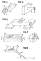
- FIG. 3 shows a measuring cell according to the invention, of tubular shape and of circular section.
- This cell has a configuration similar to that of the cell described in US 3,695,096.
- the cell 1 has the shape of a hollow cylinder of length 1 comprising two areas of concentration 2 of the force of width b located symmetrically at distances ⁇ / 2 from the center of the cell. These areas of concentration are simply grooves turned in the mass, of diameter smaller than the outside diameter of the cell. Inside the cell, at the location of the grooves, are arranged the strain gauges 3.
- the DMS are arranged under a wide of 45 ° relative to the longitudinal axis of the cell.
- Figure 4 shows the force and the angle of attack that this one on the cell.
- the direction of load 4 is directed along the axis Y and the measurement of the components Px and Py of the force using two independent sensor systems makes it possible to determine the force P acting radially on the cell independently of the angle d 'at tack ⁇ , according to the relation
- Figure 5 shows the loading conditions of a tubular measuring cell.
- the cell is placed between two supports 6 and 7 and the force P is applied between the supports by means of a pressure piece 8.
- the measuring cell 9 is embedded on one side in a fixed support 10. It is accepted that the force P acts at the center of gravity of the section of the cell and that the distribution of force in the cell section is uniform.
- the cell can be mounted so as to rotate freely in its supports or, on the contrary, be fixedly fixed. This shows that the mounting of the cell is an important factor which can only be taken into account in theory by borderline cases. The influence of the type of actual fixation of the cell can only be determined experimentally.
- a beam 11 of circular section is broken down into superimposed layers 1 - 4, and 1 '- 4'. Under the influence of a bending stress, these layers move relative to each other (example: leaf spring), which produces a shear force in the Z direction. Only the neutral layer is subjected at pure bending, the other layers are subjected to bending and elongation forces, the latter being produced by the shear force.
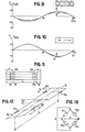
- FIG. 9 shows the curve A of the bending component measured with DMS axially arranged inside a tubular measuring cell, of circular section. The flattening due to the third harmonic is clearly visible by comparison with the setpoint curve A '.
- FIG. 10 shows the curve A of the bending component measured with DMS axially arranged on the surface of a measuring cell of circular section. The sinuisoidal behavior of the bending signal can be considered good.
- the third harmonic can be eliminated by an arrangement of the sensors as indicated in FIGS. 11 and 12.
- the latter shows that the pairs R 1 , R 2 and R 31 R 4 of sensors, placed axially, respectively in the force concentration zones 13 and 14 of the cell, are arranged in two planes 15 and 16 inclined with respect to each other by an angle l.
- Figure 13 shows the bridge connection of sensors R 1 to R 4 .
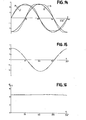
- FIG. 16 shows that the measurement error (+ 1.75%) is practically negligible, whereas, without compensation of the 3rd harmonic, this error, indicated in figure 2 is absolutely inadmissible, as already indicated above.
- the magnitude of the radial force on the cell can be measured independently of the angle of attack and using the bending stresses by the circuit of FIG. 17.
- the measurement systems 17 and 18 each comprising four strain gauges arranged as in FIG. 11 and connected as in FIG. 13 are connected to a first (19) and to a second (20) amplifier respectively delivering the output signals e 1 and e 2 .
- a quadrature operation is carried out by circuits 21 and 22 on each of these signals and the sum of their squares is carried out by an adder 23 followed by a circuit 24 executing the square root of the sum delivered by the adder and controlling a device display 25 indicating the magnitude of the radial force P, independently of its angle of attack ⁇ .
- Figure 18 shows the conditions in a beam, in the case of pure shear stresses.
- the beam has a circular section of radius r.
- F is the cross-sectional area of the beam and
- Q is the shear force acting along a line parallel to the longitudinal axis x of the beam and situated in a plane making an angle ⁇ with respect to the axis Y. It is known that at the edge of the section, the shear forces are directed along the periphery of the section and that they are zero in a direction perpen dicular.
- Figures 19 and 20 show measurement results confirming the validity of the above theoretical considerations.
- Figure 19 shows three curves A, B and C measured on the same measurement cell according to Figure 3, embedded on one side and in which the sensors are glued tangentially, perpendicular to the longitudinal axis, in the interior opening of the cell.
- the curves differ from each other by the magnitude of the applied force and the initial angle of attack of this force. It can be seen that, in accordance with the above relationship, each curve describes two periods for a 360 ° rotation of the angle of attack ⁇ of the force.
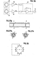
- FIG. 20 shows the curves of the resistance variations ⁇ R of the four strain gauges 1, 2, 3 and 4 arranged at an angle of 45 ° relative to the axis of the measuring cell used and represented in FIG. 21. clearly recognizes the effect of the second harmonic due to shear stresses.
- Figure 22 shows the bending (A) and shear (B) components obtained by simulation using a computer from the resistance variations measured by sensors of the cell in Figure 21. It is clearly visible that for a 360 ° rotation of the angle of attack of the radial force applied to the measurement, the bending component A describes only one period whereas the shearing component B describes two periods, in agreement with the preceding considerations.
- FIGS. 23 and 24 show the bridge connections of the sensors of FIG. 21 making it possible to eliminate respectively the effects of the shear stress during the measurement of the bending component and the effects of the bending stress during the measurement of the shear component.
- FIG. 26 shows the electronic circuit allowing the measurement of the magnitude of the force P acting radially independently of the angle of attack of this force by using the shear stresses produced in the measurement cell.
- the DMS AA 'and BB' are connected with fixed resistors so as to form the bridges 26 and 27 respectively, the output signals of which, after amplification in the amplifiers 28 and 29 are connected to the input of an adder 30, delivering to a display device 31 a signal proportional to the radial force P.
Landscapes
- Physics & Mathematics (AREA)
- General Physics & Mathematics (AREA)
- Force Measurement Appropriate To Specific Purposes (AREA)
- Measurement Of Force In General (AREA)
Priority Applications (5)
| Application Number | Priority Date | Filing Date | Title |
|---|---|---|---|
| DE8181810063T DE3168566D1 (en) | 1981-02-26 | 1981-02-26 | Cell for measuring a force with radial effect |
| AT81810063T ATE11597T1 (de) | 1981-02-26 | 1981-02-26 | Zelle zum messen einer radial wirkenden kraft. |
| EP81810063A EP0059295B1 (de) | 1981-02-26 | 1981-02-26 | Zelle zum Messen einer radial wirkenden Kraft |
| US06/338,245 US4454769A (en) | 1981-02-26 | 1982-01-11 | Radial force measuring cell |
| JP57029789A JPS57157129A (en) | 1981-02-26 | 1982-02-25 | Dadial force measuring cell |
Applications Claiming Priority (1)
| Application Number | Priority Date | Filing Date | Title |
|---|---|---|---|
| EP81810063A EP0059295B1 (de) | 1981-02-26 | 1981-02-26 | Zelle zum Messen einer radial wirkenden Kraft |
Publications (2)
| Publication Number | Publication Date |
|---|---|
| EP0059295A1 true EP0059295A1 (de) | 1982-09-08 |
| EP0059295B1 EP0059295B1 (de) | 1985-01-30 |
Family
ID=8188648
Family Applications (1)
| Application Number | Title | Priority Date | Filing Date |
|---|---|---|---|
| EP81810063A Expired EP0059295B1 (de) | 1981-02-26 | 1981-02-26 | Zelle zum Messen einer radial wirkenden Kraft |
Country Status (5)
| Country | Link |
|---|---|
| US (1) | US4454769A (de) |
| EP (1) | EP0059295B1 (de) |
| JP (1) | JPS57157129A (de) |
| AT (1) | ATE11597T1 (de) |
| DE (1) | DE3168566D1 (de) |
Cited By (1)
| Publication number | Priority date | Publication date | Assignee | Title |
|---|---|---|---|---|
| WO2003073057A1 (en) * | 2001-12-21 | 2003-09-04 | Idbike | Force measuring device |
Families Citing this family (20)
| Publication number | Priority date | Publication date | Assignee | Title |
|---|---|---|---|---|
| HU188450B (en) * | 1983-04-29 | 1986-04-28 | Vasipari Kutato Es Fejlesztoe Vallalat,Hu | Electromechanic measuring transducer pin |
| DE3435511A1 (de) * | 1984-09-27 | 1986-04-03 | Bayerische Motoren Werke AG, 8000 München | Elektrode |
| US4627341A (en) * | 1985-09-06 | 1986-12-09 | New Holland, Inc. | Bale density control sensing apparatus and method |
| US4624180A (en) * | 1985-09-06 | 1986-11-25 | New Holland, Inc. | Electronic bale density controller |
| DE4218929C1 (de) * | 1992-06-10 | 1993-09-09 | Deutsche Bundesbahn, Vertreten Durch Das Bundesbahn-Zentralamt Minden (Westf.), 4950 Minden, De | |
| US5430342A (en) * | 1993-04-27 | 1995-07-04 | Watson Industries, Inc. | Single bar type vibrating element angular rate sensor system |
| EP0892258A1 (de) * | 1997-07-15 | 1999-01-20 | SLM Schweizerische Lokomotiv- und Maschinenfabrik AG | Messanordnung für einen Radsatz eines Schienenfahrzeuges und Vorrichtung zum Anbringen einer derartigen Messanordnung an einem Radsatz |
| US6422096B1 (en) | 1998-08-06 | 2002-07-23 | Blh Electronics, Inc. | Load cell |
| US6974744B1 (en) | 2000-09-05 | 2005-12-13 | Marvell International Ltd. | Fringing capacitor structure |
| US6980414B1 (en) | 2004-06-16 | 2005-12-27 | Marvell International, Ltd. | Capacitor structure in a semiconductor device |
| DE10313828A1 (de) * | 2003-03-21 | 2004-10-28 | Bizerba Gmbh & Co. Kg | Kraftmesszelle |
| US20050120809A1 (en) * | 2003-12-09 | 2005-06-09 | Ramming John E. | Robotic force sensing device |
| JP4831830B2 (ja) * | 2006-11-01 | 2011-12-07 | 三菱重工業株式会社 | 振動計取付機構 |
| JP5202446B2 (ja) * | 2009-06-08 | 2013-06-05 | 日立建機株式会社 | 作業機械及びピン型ロードセル |
| JP2012127883A (ja) * | 2010-12-17 | 2012-07-05 | Sinfonia Technology Co Ltd | トルクセンサ及びこれを備えた駆動装置 |
| JP6110242B2 (ja) | 2013-07-09 | 2017-04-05 | 日立建機株式会社 | 荷重検出装置及びこれを備えた作業機械 |
| CN106768512B (zh) * | 2017-02-08 | 2022-09-02 | 徐州工程学院 | 一种12点方位12点受力视频显示传感器装置的显示方法 |
| WO2019032470A1 (en) * | 2017-08-05 | 2019-02-14 | Interface, Inc. | AXIAL FORCE PRESSURE TRANSDUCER |
| EP3564637A1 (de) | 2018-05-03 | 2019-11-06 | Movotec A/S | Ein kraftaufnehmer, eine messvorrichtung und ein system zur messung der muskelsteifheit |
| IL284164B2 (en) | 2018-12-20 | 2025-09-01 | Ezmems Ltd | Multiple-meter-based sensors, configurations and methods of manufacturing them |
Citations (4)
| Publication number | Priority date | Publication date | Assignee | Title |
|---|---|---|---|---|
| US3365689A (en) * | 1966-04-26 | 1968-01-23 | Kutsay Ali Umit | Strain gage apparatus |
| US3695096A (en) * | 1970-04-20 | 1972-10-03 | Ali Umit Kutsay | Strain detecting load cell |
| US3949603A (en) * | 1974-07-01 | 1976-04-13 | Hottinger Baldwin Measurements | Strain gage transducer |
| GB2009943A (en) * | 1977-12-08 | 1979-06-20 | Avery Ltd W & T | A cantilever beam force transducer |
Family Cites Families (4)
| Publication number | Priority date | Publication date | Assignee | Title |
|---|---|---|---|---|
| US3853001A (en) * | 1972-07-13 | 1974-12-10 | American Hoist & Derrick Co | Crane load measuring means |
| GB1459027A (en) * | 1974-04-26 | 1976-12-22 | Strainstall Ltd | Mooring device |
| FR2378272A1 (fr) * | 1977-01-25 | 1978-08-18 | Ferodo Sa | Dispositif dynamometrique de mesure de couple pour engin a fleche de levage a commande par verin |
| GB1577341A (en) * | 1978-02-20 | 1980-10-22 | British Hovercraft Corp Ltd | Shear pin load cell load measuring equipment |
-
1981
- 1981-02-26 EP EP81810063A patent/EP0059295B1/de not_active Expired
- 1981-02-26 AT AT81810063T patent/ATE11597T1/de active
- 1981-02-26 DE DE8181810063T patent/DE3168566D1/de not_active Expired
-
1982
- 1982-01-11 US US06/338,245 patent/US4454769A/en not_active Expired - Fee Related
- 1982-02-25 JP JP57029789A patent/JPS57157129A/ja active Pending
Patent Citations (4)
| Publication number | Priority date | Publication date | Assignee | Title |
|---|---|---|---|---|
| US3365689A (en) * | 1966-04-26 | 1968-01-23 | Kutsay Ali Umit | Strain gage apparatus |
| US3695096A (en) * | 1970-04-20 | 1972-10-03 | Ali Umit Kutsay | Strain detecting load cell |
| US3949603A (en) * | 1974-07-01 | 1976-04-13 | Hottinger Baldwin Measurements | Strain gage transducer |
| GB2009943A (en) * | 1977-12-08 | 1979-06-20 | Avery Ltd W & T | A cantilever beam force transducer |
Cited By (1)
| Publication number | Priority date | Publication date | Assignee | Title |
|---|---|---|---|---|
| WO2003073057A1 (en) * | 2001-12-21 | 2003-09-04 | Idbike | Force measuring device |
Also Published As
| Publication number | Publication date |
|---|---|
| JPS57157129A (en) | 1982-09-28 |
| ATE11597T1 (de) | 1985-02-15 |
| US4454769A (en) | 1984-06-19 |
| DE3168566D1 (en) | 1985-03-14 |
| EP0059295B1 (de) | 1985-01-30 |
Similar Documents
| Publication | Publication Date | Title |
|---|---|---|
| EP0059295B1 (de) | Zelle zum Messen einer radial wirkenden Kraft | |
| FR2852102A1 (fr) | Capteur de pression a semiconducteur ayant une membrane | |
| EP1056985B1 (de) | Dehnungsaufnehmer mit mechanischer verriegelung während des einbaus und selbstätiger kalibrierung mit hilfe dieser verriegelung | |
| EP0098796B1 (de) | Empfindliches Element für einen Dehnungswandler und Dehnungswandler der es benutzt | |
| EP2668510B1 (de) | Vorrichtung zum messen der temperatur eines vibrierenden balkens und deren verwendung zur verbesserung der messgenauigkeit eines sensors mit vibrierendem balken | |
| FR2531532A1 (fr) | Capteur piezo-electrique, notamment pour la mesure de pressions | |
| EP3766830B1 (de) | Mechanische verbindung für mechanische mems- und nems-struktur, und mems- und nems-struktur, die eine solche mechanische verbindung umfasst | |
| EP0376795B1 (de) | Ausdehnungsmesssonde zur Messung der Belastung für ein Bohrelement | |
| EP2815210A1 (de) | Kompakte vorrichtung zur erfassung mindestens einer beschleunigung und einer drehzahl | |
| EP3234529A1 (de) | Mehrdimensionaler resonanter kraftsensor | |
| FR2995995A1 (fr) | Capteur de pression a base de nanojauges couplees a un resonateur | |
| FR2826448A1 (fr) | Systeme de mesure differentielle fonde sur l'utilisation de paires de reseaux de bragg | |
| FR2799837A1 (fr) | Procede et dispositif de mesure d'efforts en presence d'une pression exterieure | |
| FR2848298A1 (fr) | Accelerometre a poutre vibrante | |
| FR2465995A1 (fr) | Procede de mesure de l'epaisseur de la paroi d'un tube | |
| EP0200587B1 (de) | Verfahren zur Einstellung eines Kraftwandlers mit Dehnungsmessstreifen und so erhaltener eingestellter Kraftwandler | |
| CA3030548A1 (fr) | Resonateur mecanique optimise pour fonctionner dans un fluide | |
| EP1423665B1 (de) | Wägeeinrichtung | |
| EP3465120B1 (de) | Mehrdimensionaler resonanter kraftsensor | |
| EP0244324B1 (de) | Kraftwandler mit Widerstandsmessstreifen | |
| FR2545214A1 (fr) | Broche electromecanique de conversion de mesure | |
| EP0291365B1 (de) | Wandler von Biege- und Drehmomenten | |
| WO2014096655A1 (fr) | Dispositif micro-electromecanique possedant au moins deux elements deformables de dimensions differentes | |
| WO2000023778A1 (fr) | Detecteur de position a cellule de detection micro-usinee | |
| FR2904687A1 (fr) | Dispositif de mesure des deformations d'un profile soumis a un ou plusieurs efforts |
Legal Events
| Date | Code | Title | Description |
|---|---|---|---|
| PUAI | Public reference made under article 153(3) epc to a published international application that has entered the european phase |
Free format text: ORIGINAL CODE: 0009012 |
|
| 17P | Request for examination filed |
Effective date: 19820107 |
|
| AK | Designated contracting states |
Designated state(s): AT BE CH DE FR GB IT NL SE |
|
| RBV | Designated contracting states (corrected) |
Designated state(s): AT BE CH DE FR GB IT LI NL SE |
|
| ITF | It: translation for a ep patent filed | ||
| GRAA | (expected) grant |
Free format text: ORIGINAL CODE: 0009210 |
|
| AK | Designated contracting states |
Designated state(s): AT BE CH DE FR GB IT LI NL SE |
|
| REF | Corresponds to: |
Ref document number: 11597 Country of ref document: AT Date of ref document: 19850215 Kind code of ref document: T |
|
| REF | Corresponds to: |
Ref document number: 3168566 Country of ref document: DE Date of ref document: 19850314 |
|
| PLBE | No opposition filed within time limit |
Free format text: ORIGINAL CODE: 0009261 |
|
| STAA | Information on the status of an ep patent application or granted ep patent |
Free format text: STATUS: NO OPPOSITION FILED WITHIN TIME LIMIT |
|
| 26N | No opposition filed | ||
| PGFP | Annual fee paid to national office [announced via postgrant information from national office to epo] |
Ref country code: NL Payment date: 19870228 Year of fee payment: 7 Ref country code: AT Payment date: 19870228 Year of fee payment: 7 |
|
| PGFP | Annual fee paid to national office [announced via postgrant information from national office to epo] |
Ref country code: FR Payment date: 19890118 Year of fee payment: 9 |
|
| PGFP | Annual fee paid to national office [announced via postgrant information from national office to epo] |
Ref country code: CH Payment date: 19890221 Year of fee payment: 9 |
|
| PG25 | Lapsed in a contracting state [announced via postgrant information from national office to epo] |
Ref country code: AT Effective date: 19890226 |
|
| PG25 | Lapsed in a contracting state [announced via postgrant information from national office to epo] |
Ref country code: SE Effective date: 19890227 |
|
| ITTA | It: last paid annual fee | ||
| PG25 | Lapsed in a contracting state [announced via postgrant information from national office to epo] |
Ref country code: BE Effective date: 19890228 |
|
| PGFP | Annual fee paid to national office [announced via postgrant information from national office to epo] |
Ref country code: GB Payment date: 19890228 Year of fee payment: 9 |
|
| PGFP | Annual fee paid to national office [announced via postgrant information from national office to epo] |
Ref country code: DE Payment date: 19890320 Year of fee payment: 9 |
|
| BERE | Be: lapsed |
Owner name: VIBRO-METER S.A. Effective date: 19890228 |
|
| PG25 | Lapsed in a contracting state [announced via postgrant information from national office to epo] |
Ref country code: NL Effective date: 19890901 |
|
| NLV4 | Nl: lapsed or anulled due to non-payment of the annual fee | ||
| PG25 | Lapsed in a contracting state [announced via postgrant information from national office to epo] |
Ref country code: GB Effective date: 19900226 |
|
| PG25 | Lapsed in a contracting state [announced via postgrant information from national office to epo] |
Ref country code: LI Effective date: 19900228 Ref country code: CH Effective date: 19900228 |
|
| GBPC | Gb: european patent ceased through non-payment of renewal fee | ||
| PG25 | Lapsed in a contracting state [announced via postgrant information from national office to epo] |
Ref country code: FR Effective date: 19901031 |
|
| REG | Reference to a national code |
Ref country code: CH Ref legal event code: PL |
|
| PG25 | Lapsed in a contracting state [announced via postgrant information from national office to epo] |
Ref country code: DE Effective date: 19901101 |
|
| REG | Reference to a national code |
Ref country code: FR Ref legal event code: ST |
|
| EUG | Se: european patent has lapsed |
Ref document number: 81810063.8 Effective date: 19900118 |