EP0059416A1 - Dispositif pour détecter des fautes de terre pour utilisation avec un circuit à courant continu - Google Patents
Dispositif pour détecter des fautes de terre pour utilisation avec un circuit à courant continu Download PDFInfo
- Publication number
- EP0059416A1 EP0059416A1 EP82101362A EP82101362A EP0059416A1 EP 0059416 A1 EP0059416 A1 EP 0059416A1 EP 82101362 A EP82101362 A EP 82101362A EP 82101362 A EP82101362 A EP 82101362A EP 0059416 A1 EP0059416 A1 EP 0059416A1
- Authority
- EP
- European Patent Office
- Prior art keywords
- component
- ground fault
- circuit
- current
- earth
- Prior art date
- Legal status (The legal status is an assumption and is not a legal conclusion. Google has not performed a legal analysis and makes no representation as to the accuracy of the status listed.)
- Granted
Links
- 239000000284 extract Substances 0.000 abstract description 3
- 230000005540 biological transmission Effects 0.000 description 9
- 239000003990 capacitor Substances 0.000 description 4
- 238000001514 detection method Methods 0.000 description 3
- 238000009499 grossing Methods 0.000 description 2
- 230000035945 sensitivity Effects 0.000 description 2
- 238000006243 chemical reaction Methods 0.000 description 1
- 238000010586 diagram Methods 0.000 description 1
- 230000004069 differentiation Effects 0.000 description 1
- 230000005284 excitation Effects 0.000 description 1
- 238000010304 firing Methods 0.000 description 1
- 239000000203 mixture Substances 0.000 description 1
- 238000012544 monitoring process Methods 0.000 description 1
- 230000007935 neutral effect Effects 0.000 description 1
Images


Classifications
-
- H—ELECTRICITY
- H02—GENERATION; CONVERSION OR DISTRIBUTION OF ELECTRIC POWER
- H02H—EMERGENCY PROTECTIVE CIRCUIT ARRANGEMENTS
- H02H3/00—Emergency protective circuit arrangements for automatic disconnection directly responsive to an undesired change from normal electric working condition with or without subsequent reconnection ; integrated protection
- H02H3/16—Emergency protective circuit arrangements for automatic disconnection directly responsive to an undesired change from normal electric working condition with or without subsequent reconnection ; integrated protection responsive to fault current to earth, frame or mass
-
- G—PHYSICS
- G01—MEASURING; TESTING
- G01R—MEASURING ELECTRIC VARIABLES; MEASURING MAGNETIC VARIABLES
- G01R27/00—Arrangements for measuring resistance, reactance, impedance, or electric characteristics derived therefrom
- G01R27/02—Measuring real or complex resistance, reactance, impedance, or other two-pole characteristics derived therefrom, e.g. time constant
- G01R27/16—Measuring impedance of element or network through which a current is passing from another source, e.g. cable, power line
- G01R27/18—Measuring resistance to earth, i.e. line to ground
-
- G—PHYSICS
- G01—MEASURING; TESTING
- G01R—MEASURING ELECTRIC VARIABLES; MEASURING MAGNETIC VARIABLES
- G01R31/00—Arrangements for testing electric properties; Arrangements for locating electric faults; Arrangements for electrical testing characterised by what is being tested not provided for elsewhere
- G01R31/50—Testing of electric apparatus, lines, cables or components for short-circuits, continuity, leakage current or incorrect line connections
- G01R31/52—Testing for short-circuits, leakage current or ground faults
-
- H—ELECTRICITY
- H02—GENERATION; CONVERSION OR DISTRIBUTION OF ELECTRIC POWER
- H02H—EMERGENCY PROTECTIVE CIRCUIT ARRANGEMENTS
- H02H1/00—Details of emergency protective circuit arrangements
- H02H1/04—Arrangements for preventing response to transient abnormal conditions, e.g. to lightning or to short duration over voltage or oscillations; Damping the influence of DC component by short circuits in AC networks
-
- H—ELECTRICITY
- H02—GENERATION; CONVERSION OR DISTRIBUTION OF ELECTRIC POWER
- H02H—EMERGENCY PROTECTIVE CIRCUIT ARRANGEMENTS
- H02H7/00—Emergency protective circuit arrangements specially adapted for specific types of electric machines or apparatus or for sectionalised protection of cable or line systems, and effecting automatic switching in the event of an undesired change from normal working conditions
- H02H7/26—Sectionalised protection of cable or line systems, e.g. for disconnecting a section on which a short-circuit, earth fault, or arc discharge has occured
- H02H7/268—Sectionalised protection of cable or line systems, e.g. for disconnecting a section on which a short-circuit, earth fault, or arc discharge has occured for DC systems
Definitions
- the present invention relates to a ground fault detecting device for use with a DC circuit, and more particularly to a ground fault detecting device for use with a DC circuit through which a DC power obtained by conversion of a poly-phase AC power by an AC-DC converter is transmitted to a load.
- One of such DC circuits is a DC power transmission system in which a poly-phase AC power is converted through an AC-DC converter into a DC power, which is applied to a load.
- One of two wires constituting the DC circuit is connected to the earth and a ground relay is usually provided for ground fault detection by monitoring the earth current flowing through the earth point. Normally, no current flows into the ground relay and thus it is not actuated. In the event that a ground fault takes place, however, a fault current flows through the ground fault point and the earth point, then actuating the ground relay.
- the DC circuit In designing the DC circuit, much care is taken so as to avoid an erroneous operation of the ground relay due to a current flowing into the ground relay by circuit of a so-called detour.
- the DC circuit generally has a stray capacitance, which may form such a detour circuit and a leak current flowing therethrough is possible to cause such an erroneous operation.
- the ground relay In order to avoid this erroneous operatiorr, the ground relay has hitherto been arranged to actuate when the ground current is detected to be sufficiently large. This measure is very effective to avoid the erroneous operation caused by a usual leak current due to the stray capacitance.
- an object of the present invention is to provide a ground fault detecting device for use with a DC circuit, which can prevent an erroneous operation which may be caused by a leak current produced when the poly-phase AC current is converted through an AC-DC converter into a DC current.
- the leak current includes a harmonic component of the DC current generated when the AC phase-voltages are unbalanced.
- the harmonic component is removed from the earth current flowing through the earth point and the remaining component is used for detection of grounded fault.
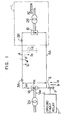
- Fig. 1 illustrates an arrangement of a DC power transmission system which is possible to be influenced by a stray capacitance.
- a DC power transmission system is connected between two AC power transmission systems, through transformers 2A and 2B.
- the DC power transmission system includes AC-DC converters lA and 1B, smoothing reactors 3A and 3B, and a DC power transmission line including a neutral line 4A.
- a DC current transformer (DCCT) 6 and a ground fault relay 7 are provided at an earth point P of the DC power transmission system.
- DCCT DC current transformer
- the DC transformer 6 detects the ground current and the ground fault detecting relay 7 judges whether or not the ground current reaches the level generally produced by a ground fault. When it reaches the fault level, it judges that a ground fault takes place. In other words, it judges that a ground fault takes place, when the current flowing through the route including the ground fault point and the earth point exceeds the fault level.
- the smoothing reactor 3B, the AC-DC converter lB operating as an inverter mode and the transformer 2B correspond to a load L.
- a leak current Is flows into the ground relay 7 through a stray capacitor Cs.
- Figs. 2a, 2b and 2c illustrate waveforms of an AC voltage VAC, a DC voltage V DC and a DC current I DC respectively, of the AC-DC converter lA operating in a rectifying mode.
- the abscissa t represents time.
- These waveforms illustrate, by way of example, those in case of full-wave rectification of an AC voltage of three phases of U, V and W.
- solid lines indicate the waveforms of V A C, V DC and I DC appeared when the three phase-voltages are balanced. Dot lines indicate the waveforms appeared when only the V-phase voltage is dropped, as an example where the phase voltages are unbalanced. As seen from Fig.
- the DC current I DC includes a DC component of constant level and a ripple component which is the six-th harmonics of the basic AC component when the phase voltages are balanced, but includes an additional component having a frequency two times of the frequency of the basic AC component when the phase voltages are unbalanced.
- the additional component corresponds to the second harmonics of the basic AC component.
- the ripple current of six-th harmonics and the harmonics due to unbalance of phase-voltages flow, as leak current, into the ground relay 7 through the stray capacitance Cs.
- An amount of the ripple current can previously be calculated on the basis of the firing phase angle of the AC-DC converter, and is generally very small such as 10% or less of the rated value of I DC . Therefore, the erroneous operation due to the ripple current may easily be avoided by adjusting an operating threshold of the ground relay.
- An amplitude of the higher harmonics due to the unbalance of phase-voltages changes depending on the degree of the imbalance, and it is sometimes much larger than that of the ripple current.
- the worst condition of the voltage imbalance occurs when one of the three phases is open, resulting in several tens % or more % of the rated value of I DC to flow as Is. It might be possible to adjust the operating threshold or sensitivity of the ground relay to such a value as to prevent the ground relay from erroneously operating, by previously calculating an amplitude of the harmonics in the worst unbalanced condition. According to this approach, however, there would be a great possibility that the relay can not discriminate the ground fault from-the imbalance of phase-voltages resulting in failure of correctly detecting the ground fault. Therefore, this approach is not effective to prevent the ground relay from erroneous operation.
- the voltage unbalanced condition resulting in erroneous operation sometimes occurs from an excitation rush current when the transformer in the AC system is made active.
- the AC system with an insufficient transportation of transmission lines is likely to fall in the voltage unbalanced condition. Therefore, in the ground detecting device for the DC circuit, it is desired to provide a measure for preventing the ground detecting device from erroneously operation even when the harmonics appear due to the AC voltage unbalanced condition.
- the device of the present invention is arranged to detect the ground fault from the detected earth current subtracted by an AC component thereof.
- An embodiment of the present invention is shown in Fig. 3.
- reference numeral 6 designates a DC current transformer (DCCT); 8 a differential circuit;. 9 an adder; 10 a full-wave rectifier circuit; 7' a judging circuit.
- DCCT 6 and the judging circuit 7' are similar to those used in the prior device, while the circuits 8 to 10 are additionally used according to the present invention.
- the DCCT 6 includes a detection coil 60, an exciting power source 61, a rectifier bridge 62, a bias coil 63, a bias power source 16, and a resistor 65.
- This arrangement constitutes a so-called polarity DCCT capable of detecting also both polarities of currents. That is, it can detect both DC and AC.
- the differential circuit 8 includes a capacitor 80 for differentiation, a resistor 81, an inverting amplifier 80, and a feedback resistor 82.
- the differential circuit 8 extracts an AC component from the output signal from the DCCT 6 and produces an inversion of the AC component.
- the adder 9 including resistors 90 to 92 and an inverting amplifier 93 adds the output signal from the DCCT 6 and the output of the differential circuit 8, i.e. an inversion of the AC component to produce an inverted output signal.
- the inverted output signal corresponds to the DC component obtained by subtracting the AC component from the output signal of the DCCT 6.
- the full-wave rectifier circuit 10 made up of diodes 100 and 101, resistors 102 and 104, and an inverting amplifier 103, is used to detect the absolute value of the DC component in the output of the adder 9.
- the judging circuit 7' includes resistors 70 to 72, and 76, a comparator 73, a diode 74, a transistor 75, and an inverting gate 77.
- the output signal from the full-rectifier circuit 10 is compared with a predetermined reference level preset by a potention meter 70 by a comparator 73.
- the output of the comparator is applied through the diode 74 to the transistor 77 thereby to render it conductive and the inverting gate 77 produces an output signal of "1".
- the level of "1" indicates the presence of ground fault.
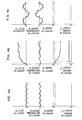
- Figs. 4a, 4b and 4c illustrate waveforms of signals at various points in the circuit shown in Fig. 3, respectively, under normal operating condition, occurrence of ground fault, and condition of imbalance of phase-voltages.
- the current detected by the DCCT 6 is analysed as follows.
- the current is composed of almost only the ripple component of six-th harmonics under the normal condition.
- the ripple component is produced when the three-phase AC current is rectified.
- the current deteced under occurrence of ground fault includes a large portion of the fault-current IF and a small portion of the leak current Is.
- the detected current includes an oscillating current as well as the DC component. Only a leak current Is flows when the AC phase-voltages are unbalanced and it is a mixture of the 2nd and 6th harmonics in the example of Fig. 2. It is understood, therefore, that the DC component is detected only when the ground fault occurs as shown in Fig. 4b.
- the detected signal is applied to the differential circuit 8 where the DC component is removed, and only an AC component is inputted into the adder 9 through the resistor 90.
- the AC component is inverted in polarity with respect to the output signal from the rectifying bridge 62.
- the output signal from the rectifier circuit 62 is applied through the resistor 91 to the adder 9.
- the AC components are opposite in polarity and hence these AC components are cancelled each other in the adder.
- only the DC component, if any., is produced by the adder 9. In this way, the AC components are removed, so that the output signal from the adder 9 is almost zero at the normal condition as shown in Fig.
- the adder 9 produces an output of substantial level only when the ground fault occurs so that the DC component is contained in the output of the DCCT 6.
- the DC output signal is applied to the full-wave rectifier 10, whose output is inputted into the comparator 73.
- the cancellation of the AC component contained in the detected earth current is carried out by extracting the AC component from the detected current and adding an inversion of the extracted AC component to the detected current.
- any of the following two arrangements shown in Figs. 5 and 6 may be used.
- Fig. 5 shows another embodiment of the present invention.
- the output of the polarized DCCT 6 is branched into two routes, one including a capacitor 40, an inverting amplifier 41 and a rectifier circuit 42, and the other including a rectifier circuit 43.
- the output signals produced from the two routes are subjected to subtraction and the result is applied to the relay 7'.
- the AC component is detected and rectified through the capacitor 40, the inverting amplifier 41 and the rectifier circuit 42.
- the rectified output signal is subtracted from another rectified signal from the rectifier 43, so that the AC component due to the unbalanced phase-voltages is cancelled.
- a very small DC component, if any, resulted from the subtraction and the DC component due to ground fault are inputted into the judging circuit 7'. Consequently, the ground fault is correctly detected, as in the embodiment shown in Fig. 3.
- Fig. 6 shows yet another embodiment of the present invention.
- a low-pass filter 45 and a rectifier circuit 46 are inserted between the polarized DCCT 6 and the judging circuit 7'. This arrangement can simply extract only the DC component.
- the ground fault detecting device for use which a DC circuit according to the present invention assures reliable operation even at the presence of the second harmonics due to imbalance of phase-voltages in the AC system.
- the fault detecting device is highly sensitive to the ground fault, since there is no need for setting the detecting level at unnecessary high level accompanied by the sensitivity reduction.
Landscapes
- Physics & Mathematics (AREA)
- General Physics & Mathematics (AREA)
- Engineering & Computer Science (AREA)
- Power Engineering (AREA)
- Emergency Protection Circuit Devices (AREA)
- Testing Of Short-Circuits, Discontinuities, Leakage, Or Incorrect Line Connections (AREA)
Applications Claiming Priority (2)
| Application Number | Priority Date | Filing Date | Title |
|---|---|---|---|
| JP27001/81 | 1981-02-27 | ||
| JP56027001A JPS57142568A (en) | 1981-02-27 | 1981-02-27 | Earth trouble detecting device for dc power transmission system |
Publications (2)
| Publication Number | Publication Date |
|---|---|
| EP0059416A1 true EP0059416A1 (fr) | 1982-09-08 |
| EP0059416B1 EP0059416B1 (fr) | 1985-11-21 |
Family
ID=12208894
Family Applications (1)
| Application Number | Title | Priority Date | Filing Date |
|---|---|---|---|
| EP82101362A Expired EP0059416B1 (fr) | 1981-02-27 | 1982-02-23 | Dispositif pour détecter des fautes de terre pour utilisation avec un circuit à courant continu |
Country Status (4)
| Country | Link |
|---|---|
| US (1) | US4430683A (fr) |
| EP (1) | EP0059416B1 (fr) |
| JP (1) | JPS57142568A (fr) |
| DE (1) | DE3267492D1 (fr) |
Cited By (3)
| Publication number | Priority date | Publication date | Assignee | Title |
|---|---|---|---|---|
| EP1612054A1 (fr) | 2004-07-02 | 2006-01-04 | Fuji Photo Film Co., Ltd. | Matériau pour l'enregistrement par jet d'encre |
| DE102010037995A1 (de) * | 2010-10-05 | 2012-04-05 | Phoenix Contact Gmbh & Co. Kg | Stromversorgungsgerät und Stromversorgungssystem mit ebensolchem |
| CN107533096A (zh) * | 2015-02-19 | 2018-01-02 | Nec能源解决方案股份有限公司 | 检测采用dc/ac功率转换系统的能量存储和/或生成系统中的接地故障的系统 |
Families Citing this family (12)
| Publication number | Priority date | Publication date | Assignee | Title |
|---|---|---|---|---|
| DE3941885A1 (de) * | 1989-12-19 | 1991-06-20 | Philips Patentverwaltung | Stromversorgungseinrichtung mit unsymmetrieueberwachungsschaltung |
| JPH066073U (ja) * | 1992-06-25 | 1994-01-25 | 株式会社明電舎 | 直流電化システムの直流高圧接地保護回路 |
| US5909365A (en) * | 1997-06-30 | 1999-06-01 | Motorola Inc. | Leakage current power supply |
| US6262565B1 (en) | 1999-05-07 | 2001-07-17 | Mytech Corporation | Electrical load switch |
| GB201102031D0 (en) * | 2011-02-07 | 2011-03-23 | Rolls Royce Plc | Protection system for an electrical power network |
| US9046555B2 (en) * | 2011-12-19 | 2015-06-02 | Tyco Safety Products Canada Ltd. | Latching over-current protection circuit and method |
| EP2837942B1 (fr) * | 2012-04-09 | 2019-08-21 | Toshiba Mitsubishi-Electric Industrial Systems Corporation | Circuit de détection de défaut de mise à la terre et dispositif de conversion de puissance l'utilisant |
| GB201400702D0 (en) * | 2014-01-16 | 2014-03-05 | Rolls Royce Plc | Rectifier diode fault detection in brushless exciters |
| FR3071928B1 (fr) * | 2017-09-29 | 2019-11-22 | Alstom Transport Technologies | Circuit de detection de defaut de masse, chaine de transformation comprenant un tel circuit, procede de detection de defaut de masse. |
| CN110967652B (zh) * | 2019-12-02 | 2022-01-25 | 国网河南省电力公司电力科学研究院 | 一种适应于谐波环境的小电流接地故障识别方法及系统 |
| CN113238169B (zh) * | 2021-03-16 | 2024-04-16 | 联合汽车电子有限公司 | 失地检测方法、可读存储介质及车辆 |
| CN218482648U (zh) * | 2022-06-28 | 2023-02-14 | 上海荣威塑胶工业有限公司 | 用于水池装置的漏电保护装置和水池装置 |
Citations (4)
| Publication number | Priority date | Publication date | Assignee | Title |
|---|---|---|---|---|
| US3978400A (en) * | 1974-11-25 | 1976-08-31 | Square D Company | Ground fault detector with a nonlinear sensing means |
| US4021729A (en) * | 1975-12-03 | 1977-05-03 | I-T-E Imperial Corporation | Cross-field ground fault sensor |
| DE2851381A1 (de) * | 1978-02-02 | 1979-08-09 | Felten & Guilleaume Carlswerk | Fehlerstrom-schutzschaltung fuer gleichund/oder wechselstrom |
| EP0005694A2 (fr) * | 1978-05-22 | 1979-11-28 | Nicolas Gath | Disjoncteur de protection contre des courants de défaut |
Family Cites Families (2)
| Publication number | Priority date | Publication date | Assignee | Title |
|---|---|---|---|---|
| US3609534A (en) | 1969-05-07 | 1971-09-28 | Gurevich Albert E | Device utilizing dc transformers for selective location of earth connection within bus system |
| JPS5246459A (en) * | 1975-10-08 | 1977-04-13 | Toshiba Corp | Protecting device of neutral conductor grounding detection |
-
1981
- 1981-02-27 JP JP56027001A patent/JPS57142568A/ja active Granted
-
1982
- 1982-02-23 DE DE8282101362T patent/DE3267492D1/de not_active Expired
- 1982-02-23 EP EP82101362A patent/EP0059416B1/fr not_active Expired
- 1982-02-24 US US06/351,766 patent/US4430683A/en not_active Expired - Lifetime
Patent Citations (4)
| Publication number | Priority date | Publication date | Assignee | Title |
|---|---|---|---|---|
| US3978400A (en) * | 1974-11-25 | 1976-08-31 | Square D Company | Ground fault detector with a nonlinear sensing means |
| US4021729A (en) * | 1975-12-03 | 1977-05-03 | I-T-E Imperial Corporation | Cross-field ground fault sensor |
| DE2851381A1 (de) * | 1978-02-02 | 1979-08-09 | Felten & Guilleaume Carlswerk | Fehlerstrom-schutzschaltung fuer gleichund/oder wechselstrom |
| EP0005694A2 (fr) * | 1978-05-22 | 1979-11-28 | Nicolas Gath | Disjoncteur de protection contre des courants de défaut |
Cited By (9)
| Publication number | Priority date | Publication date | Assignee | Title |
|---|---|---|---|---|
| EP1612054A1 (fr) | 2004-07-02 | 2006-01-04 | Fuji Photo Film Co., Ltd. | Matériau pour l'enregistrement par jet d'encre |
| DE102010037995A1 (de) * | 2010-10-05 | 2012-04-05 | Phoenix Contact Gmbh & Co. Kg | Stromversorgungsgerät und Stromversorgungssystem mit ebensolchem |
| WO2012045788A2 (fr) | 2010-10-05 | 2012-04-12 | Phoenix Contact Gmbh & Co. Kg | Bloc d'alimentation électrique et système d'alimentation électrique comprenant ce bloc d'alimentation électrique |
| WO2012045788A3 (fr) * | 2010-10-05 | 2013-03-28 | Phoenix Contact Gmbh & Co. Kg | Bloc d'alimentation électrique et système d'alimentation électrique comprenant ce bloc d'alimentation électrique |
| CN103270425A (zh) * | 2010-10-05 | 2013-08-28 | 凤凰通讯两合有限公司 | 供电器和具有这种供电器的供电系统 |
| DE102010037995B4 (de) * | 2010-10-05 | 2015-07-02 | Phoenix Contact Gmbh & Co. Kg | Stromversorgungsgerät und Stromversorgungssystem mit ebensolchem |
| CN103270425B (zh) * | 2010-10-05 | 2016-05-04 | 凤凰通讯两合有限公司 | 供电器和具有这种供电器的供电系统 |
| CN107533096A (zh) * | 2015-02-19 | 2018-01-02 | Nec能源解决方案股份有限公司 | 检测采用dc/ac功率转换系统的能量存储和/或生成系统中的接地故障的系统 |
| CN107533096B (zh) * | 2015-02-19 | 2020-11-13 | Nec能源解决方案股份有限公司 | 检测能量存储和/或生成系统中的接地故障的系统 |
Also Published As
| Publication number | Publication date |
|---|---|
| EP0059416B1 (fr) | 1985-11-21 |
| US4430683A (en) | 1984-02-07 |
| JPH0155424B2 (fr) | 1989-11-24 |
| JPS57142568A (en) | 1982-09-03 |
| DE3267492D1 (en) | 1986-01-02 |
Similar Documents
| Publication | Publication Date | Title |
|---|---|---|
| US4430683A (en) | Ground fault detecting device for use with a DC circuit | |
| JP3763852B2 (ja) | 交流電源における絶縁および障害電流の監視方法および監視回路 | |
| JP3468817B2 (ja) | 界磁地絡検出器 | |
| EP0299060B1 (fr) | Analyseur de faute de grande impedance dans un systeme de distribution d'energie electrique | |
| JP2608701B2 (ja) | 保護装置の点検回路 | |
| US5627712A (en) | Transformer differential relay | |
| US5126678A (en) | A.C. Generator fault detector | |
| US4589050A (en) | Method and apparatus for the protection of a thyristor power conversion system | |
| US4873602A (en) | Ripple attenuator for AC power transmission line protective relays | |
| JP2980698B2 (ja) | インバータ装置 | |
| JP3287121B2 (ja) | 電圧低下検出回路 | |
| JPH11174105A (ja) | 交流フィルタ回路の異常検出装置 | |
| JPH10221397A (ja) | 漏電検出器 | |
| KR102551607B1 (ko) | 누전 차단기 | |
| JP2000023470A (ja) | トランスレスインバータの保護装置 | |
| US3973185A (en) | Circuit for monitoring the inductance of an inductive load to indicate occurrence of a fault | |
| JPH09182449A (ja) | 漏電検出装置 | |
| JPH0757064B2 (ja) | 漏電電流トランスデューサ | |
| JPS5852838Y2 (ja) | 変圧器保護装置 | |
| JPH07163042A (ja) | 短絡事故高速判定回路 | |
| JPH0336920A (ja) | 回転電機地絡保護装置 | |
| JPH0131969Y2 (fr) | ||
| JPS598130B2 (ja) | 非接地直流回路の地絡監視用回路装置 | |
| JPS6229962B2 (fr) | ||
| JPH01214220A (ja) | 比率差動継電器の高調波抑制方式 |
Legal Events
| Date | Code | Title | Description |
|---|---|---|---|
| PUAI | Public reference made under article 153(3) epc to a published international application that has entered the european phase |
Free format text: ORIGINAL CODE: 0009012 |
|
| AK | Designated contracting states |
Designated state(s): DE SE |
|
| 17P | Request for examination filed |
Effective date: 19830127 |
|
| GRAA | (expected) grant |
Free format text: ORIGINAL CODE: 0009210 |
|
| AK | Designated contracting states |
Designated state(s): DE SE |
|
| REF | Corresponds to: |
Ref document number: 3267492 Country of ref document: DE Date of ref document: 19860102 |
|
| PLBE | No opposition filed within time limit |
Free format text: ORIGINAL CODE: 0009261 |
|
| STAA | Information on the status of an ep patent application or granted ep patent |
Free format text: STATUS: NO OPPOSITION FILED WITHIN TIME LIMIT |
|
| 26N | No opposition filed | ||
| EAL | Se: european patent in force in sweden |
Ref document number: 82101362.0 |
|
| PGFP | Annual fee paid to national office [announced via postgrant information from national office to epo] |
Ref country code: SE Payment date: 20001227 Year of fee payment: 20 |
|
| PGFP | Annual fee paid to national office [announced via postgrant information from national office to epo] |
Ref country code: DE Payment date: 20010330 Year of fee payment: 20 |
|
| EUG | Se: european patent has lapsed |
Ref document number: 82101362.0 |