EP0059443B1 - Véhicule qui peut être retenu par rapport à une voie à l'aide d'un dispositif magnétique d'attraction - Google Patents
Véhicule qui peut être retenu par rapport à une voie à l'aide d'un dispositif magnétique d'attraction Download PDFInfo
- Publication number
- EP0059443B1 EP0059443B1 EP82101459A EP82101459A EP0059443B1 EP 0059443 B1 EP0059443 B1 EP 0059443B1 EP 82101459 A EP82101459 A EP 82101459A EP 82101459 A EP82101459 A EP 82101459A EP 0059443 B1 EP0059443 B1 EP 0059443B1
- Authority
- EP
- European Patent Office
- Prior art keywords
- vehicle
- spring element
- spring
- vehicle according
- track
- Prior art date
- Legal status (The legal status is an assumption and is not a legal conclusion. Google has not performed a legal analysis and makes no representation as to the accuracy of the status listed.)
- Expired
Links
- 230000005291 magnetic effect Effects 0.000 title claims abstract description 34
- 230000008878 coupling Effects 0.000 claims abstract description 19
- 238000010168 coupling process Methods 0.000 claims abstract description 19
- 238000005859 coupling reaction Methods 0.000 claims abstract description 19
- 238000005086 pumping Methods 0.000 claims description 5
- 230000009467 reduction Effects 0.000 claims description 4
- 238000005339 levitation Methods 0.000 abstract description 3
- 230000004075 alteration Effects 0.000 abstract 1
- 238000005096 rolling process Methods 0.000 description 8
- 230000002349 favourable effect Effects 0.000 description 6
- 230000033001 locomotion Effects 0.000 description 6
- 230000008859 change Effects 0.000 description 4
- 230000007423 decrease Effects 0.000 description 3
- 230000033228 biological regulation Effects 0.000 description 2
- 230000006835 compression Effects 0.000 description 2
- 238000007906 compression Methods 0.000 description 2
- 238000011161 development Methods 0.000 description 2
- 230000018109 developmental process Effects 0.000 description 2
- 230000001105 regulatory effect Effects 0.000 description 2
- 239000000725 suspension Substances 0.000 description 2
- 238000004804 winding Methods 0.000 description 2
- 244000089409 Erythrina poeppigiana Species 0.000 description 1
- 235000009776 Rathbunia alamosensis Nutrition 0.000 description 1
- 229910000831 Steel Inorganic materials 0.000 description 1
- 230000009471 action Effects 0.000 description 1
- 230000006978 adaptation Effects 0.000 description 1
- 230000000712 assembly Effects 0.000 description 1
- 238000000429 assembly Methods 0.000 description 1
- 230000005540 biological transmission Effects 0.000 description 1
- 238000007599 discharging Methods 0.000 description 1
- 230000005294 ferromagnetic effect Effects 0.000 description 1
- 239000003302 ferromagnetic material Substances 0.000 description 1
- 239000012530 fluid Substances 0.000 description 1
- 230000003993 interaction Effects 0.000 description 1
- 230000007246 mechanism Effects 0.000 description 1
- 230000001141 propulsive effect Effects 0.000 description 1
- 230000000087 stabilizing effect Effects 0.000 description 1
- 239000010959 steel Substances 0.000 description 1
- 238000009423 ventilation Methods 0.000 description 1
Images
Classifications
-
- B—PERFORMING OPERATIONS; TRANSPORTING
- B61—RAILWAYS
- B61B—RAILWAY SYSTEMS; EQUIPMENT THEREFOR NOT OTHERWISE PROVIDED FOR
- B61B13/00—Other railway systems
- B61B13/08—Sliding or levitation systems
-
- B—PERFORMING OPERATIONS; TRANSPORTING
- B61—RAILWAYS
- B61F—RAIL VEHICLE SUSPENSIONS, e.g. UNDERFRAMES, BOGIES OR ARRANGEMENTS OF WHEEL AXLES; RAIL VEHICLES FOR USE ON TRACKS OF DIFFERENT WIDTH; PREVENTING DERAILING OF RAIL VEHICLES; WHEEL GUARDS, OBSTRUCTION REMOVERS OR THE LIKE FOR RAIL VEHICLES
- B61F5/00—Constructional details of bogies; Connections between bogies and vehicle underframes; Arrangements or devices for adjusting or allowing self-adjustment of wheel axles or bogies when rounding curves
- B61F5/02—Arrangements permitting limited transverse relative movements between vehicle underframe or bolster and bogie; Connections between underframes and bogies
- B61F5/04—Bolster supports or mountings
Definitions
- the invention relates to a vehicle according to the preamble of claim 1.
- the spring device In a known vehicle of this type (DE-C-27 11 994), the spring device consists of helical springs arranged between the payload carrier and the supporting part.
- the coupling means are connected to the payload carrier and are effective between the payload carrier, a support structure of the vehicle part of the magnetic device and the position-defining device.
- the coupling means detect the load condition of the vehicle through the changes in length of the springs.
- the invention has for its object to provide a vehicle of the type mentioned, in which one can align the vehicle suspension overall more favorable to the respective needs despite the described need to maintain a certain spring characteristic for the current gap width adjustment of the magnetic device.
- the position-defining device can be implemented in particular by wheels that can be unrolled on the track and / or electromagnets that can be changed in their magnetic force and / or by means of assemblies comprising at least one electromagnet and at least one wheel.
- the coupling means are preferably designed so that the gap width changes induced by them are smaller than the deformation paths detected on the spring device.
- the attractive magnetic device is preferably constructed with permanent magnets on the vehicle part and laminated, ferromagnetic parts on the track part.
- the magnetic device preferably also provides the propulsive forces for the vehicle according to DE-C-23 39 060. Holding the vehicle against the travel path essentially means holding vertically against weight and possibly inertial forces and disturbing forces and / or essentially horizontally Hold, for example against inertial forces when cornering or disturbing forces such as wind forces, and / or a hold against any other forces that could bring the vehicle from the intended relative position to the route.
- the position-defining device serves as a support for the coupling means, so to speak To bring vehicle part of the magnetic device closer to the track part or to be able to remove it from the track part.
- the position-defining device can also be referred to as an additional force device It makes sense to adapt the holding force supplied by the magnetic device as well as possible to the size of the holding force required in each case. More detailed explanations of the points described above can be found in DE-C-23 39 060 and DE-C-27 11 994. and the content of these publications is expressly incorporated into the present application by reference as part of the disclosure.
- the spring element on which the load state of the vehicle is not recorded, is preferably designed as a pneumatic spring element, for example in the form of a gas or air-filled bellows.
- a pneumatic spring element for example in the form of a gas or air-filled bellows.
- the pneumatic spring element or in pairs, pneumatic spring elements for level adjustment or regulation of the payload carrier and / or for the specific inclination of the payload carrier about a roll axis lying in the vehicle longitudinal direction when cornering can be used. It has been shown that it is quite difficult to build the track for a vehicle held with the aid of a magnetic device on the outside of the curve too high because the track must be adjusted very precisely. The problems increase when you have two routes for vehicles or switches in the curve.
- the invention provides a structurally very simple possibility of being able to build the route without curve elevation and nevertheless to incline the vehicle in curves relative to the route, which is favorable for the convenience of transportation.
- additional functions of the spring device such as level adjustment and inclination of the payload carrier when cornering, are available without the coupling means being influenced thereby, so that the desired adjustment of the gap width of the magnetic device to the holding force required in each case can still take place and unaffected .
- the further developments of the invention according to claims 5, 6 and 7 are favorable in terms of space requirement or in terms of adaptation to the special room conditions that exist in magnetic levitation vehicles.
- An arrangement of the first spring elements on the left and right as far as possible on the outside of the payload carrier is advantageous in the interest of stabilizing them against rolling movements of the payload carrier.
- the first spring elements can advantageously have a low height, which is advantageous with regard to the overall vehicle height and the investment costs for tunnel structures.
- the second spring elements can be arranged further to the left and right further inside of the vehicle, where there is sufficient space available.
- the coupling means are preferably provided in pairs for the left and right side of the vehicle.
- the principle can be realized that increases and decreases in the lateral areas of the payload carrier relative to the vehicle due to rolling motion lead to different changes in the gap width compared to increases and decreases in the payload carrier relative to the vehicle relative to the movement. Further details can be found in the description of a preferred exemplary embodiment below and in DE-A-29 33 447, the content of which is expressly made part of the disclosure of the present application by reference.
- the vehicle according to the invention is equipped with a braking device, then it is favorable to arrange the braking device on the supporting part in such a way that it is essentially constant in position with respect to the travel path, i.e. regardless of the load condition of the vehicle, the deformation condition of the spring device and the position of the vehicle part magnetic device relative to the travel path always maintains essentially the same relative position to the travel path, so that the brake ventilation play to be traversed when braking from the brake pads remains essentially the same and also remains substantially the same with one another in all brake pads acting on all sides of the travel path.
- the simplest way to achieve this is to attach the braking device to the position-defining device, which already has the essentially constant relative position to the travel path.
- the vehicle according to the invention preferably has a spring-loaded braking device.
- a spring-loaded brake device a cylinder-piston unit that counteracts the spring-loaded mechanism can be provided, whose residual pressure is adjustable via a pressure reducing valve. In this way, it can be ensured, for example, with a lower load on the utility carrier, that the brake pad pressure forces exerted by the spring accumulator are smaller, and vice versa.
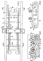
- the vehicle 2 has a payload carrier 4, for example in the form of a passenger cabin, and a support part 6.
- a payload carrier 4 for example in the form of a passenger cabin
- a support part 6 for example in the form of a passenger cabin
- the travel path 8 can also be seen in cross-section, while the travel path 8 in Fig. 2 is omitted for reasons of clarity.
- the entire support part 6 of the vehicle 2 consists of two bogie-like parts, one of which is arranged near the front end of the vehicle 2 and one near the rear end of the vehicle 2; 2 shows one of these bogie-like parts.
- the two bogie-like parts have the same structure, so that only one is described below.
- Each bogie-like part consists essentially of a support structure 10 for the vehicle part 12 of the magnetic device 14.
- the support structure 10 consists essentially of two side members 16, a series of cross members 18 distributed along the side members 16, which are fastened to the underside of the side members 16 and protrude outwards on both sides beyond the side members 16, two further side members 19, each of which is connected to the free ends of the cross members 18, and a cross member 20 which - with respect to the longitudinal direction of the vehicle 2 - in the middle of the side members 26 at right angles to these and is arranged parallel to the cross beams 18.
- the crossbeam 20 is fastened to the upper sides of the longitudinal beams 16 and projects outward on both sides thereof.
- two transverse levers 22 are rotatably mounted about an axis 24 lying in the longitudinal direction of the vehicle, one transverse lever 22 in the longitudinal direction of the vehicle in front of the transverse crossbeam 20 and one transverse lever 22 in the longitudinal direction of the vehicle behind the transverse crossbeam 20.
- the two transverse levers 22 of each side of the vehicle are connected to one another in the end region of their outer arms 26 by a horizontal plate 28 and thus functionally constitute a (common) transverse lever 22, as is addressed in the claims.
- a rod 32 leads downward, which is firmly connected to a horizontal disc 34 below.
- a coil spring 38 is arranged in each case.
- a compressed air-filled bellows 40 rests on the plate 28 on the outer arm 26 of each pair of transverse levers 22.
- the payload carrier 4 rests on the two spring bellows 40.
- the payload carrier 4 is connected to the support part 6 or the two bogie-like parts of the support part 6 by a handlebar (not shown) and / or by a vertical pin (not shown) which leads through the center of the crossbar 20 with respect to the transverse direction of the vehicle .
- Each bogie-like part of the support part 6 is symmetrical with respect to a plane running transversely to the vehicle 2 through the center of the crossmember 20 and with respect to a plane running in the longitudinal direction of the vehicle 2 through the centers of the cross members 18.
- the bellows 40 When the payload carrier 4 is deflected relative to the supporting part 6, the bellows 40 are deformed in a compressive manner and the coil springs 30 are compressed between the respective disk 34 and the respective plate 36 due to the action of the respective rod 32.
- the parallel arrangement of two coil springs 38 functionally represents a (common) spring element.
- a longitudinal lever 42 leads from each (single) cross lever 22 just outside the respective longitudinal member 16 in the vehicle longitudinal direction to the front or to the rear.
- Each longitudinal lever 42 is articulated on the associated (single) transverse lever 22 in the area between the axis 24 and the connection point of the rod 32.
- Each longitudinal lever 42 is further articulated on the associated longitudinal beam 16 in the end region thereof so as to be pivotable about a horizontal axis.
- the front ends of the two longitudinal levers 42 which extend forward from the transverse levers 22 lying in front of the crossbar 20 in the longitudinal direction of the vehicle, are articulated on a support body 44 extending transversely to the longitudinal direction of the vehicle.
- each bogie-like part there is a support body 44, that is, a total of four supporting bodies 44 are provided for the entire supporting part 6.
- the support bodies 44 are located in front of or behind the ends of the longitudinal beams 16.
- Each support body 44 carries left and right in each case an upper wheel 46 with a horizontal axis, a lower wheel 48 with a horizontal axis and a side guide wheel 50 with a vertical axis.
- each support 52 On the inner edge of each support 52, a longitudinal angle support 56 is fastened with its vertical leg, the horizontal leg projecting inwards in each case.
- the horizontal leg of each angle bracket 56 serves with its top as a rolling surface for the upper wheels 46 and with its underside as a rolling surface for the lower wheels 48.
- the inner surface of the vertical leg of each angle bracket 56 serves as a rolling surface for the side guide wheels 50.
- the supporting part 6 or each bogie-like part of the supporting part 6 has a roughly speaking cross-sectionally a double-T-shaped configuration, in which the upper flange, as it were, given by the cross-beam 20 and extended outwards by the cross-lever 22, laterally Raises outward beyond the angle brackets 56 and the brackets 52, the middle region, given by the longitudinal beams 16, extends between the two angle brackets 56, and the lower flange, given by the crossbeams 18, extends outward on both sides to below the brackets 52 and the stators 54 on both sides extends.
- the coil springs 38 are each arranged just inside the side members 16.
- the position-defining device 44, 46, 48, 50 is guided in a constant position overall on the travel path 8 and represents, so to speak, the fixed point of the entire system. If the payload bracket 4 is the same on the right and left lowered by a certain amount relative to the travel path 8, for example by boarding passengers, the outer arms 26 of the transverse levers 22 are lowered and the inner arms 30 of the transverse levers 22 are raised.
- the respective lever arm length ratio of the longitudinal levers 42 namely the distance between the connection point on the transverse lever 22 and the connection point on the support body 44 to the distance between the connection point on the side member 16 and the connection point on the support body 44, is approximately 5: 1, so that the swiveling occurring at the connection point 58 is converted into a reduction in the gap width of the magnetic device 14 with path reduction in a ratio of 5: 1.
- this change in gap width depending on the load condition of the payload carrier 4 reference is expressly made to DE-C-27 11 994.
- the longitudinal levers 42 with their articulation on the front levers 22, the support structure 10 and the supporting bodies 44 of the position-defining device represent coupling means as a whole, which adjust the gap width s of the attracting magnetic device 14 as a function of the load state of the vehicle 2 such that when the load increases, a Lowering the gap width s results and vice versa. In this way, it is ensured that the magnetic device 14 always applies the overwhelming majority of the total holding or carrying force required, while the wheels 46, 48 only have to apply a small proportion of the remaining force.
- a pivoting of the longitudinal levers 42 depends only on the pivoting state of the transverse levers 22, that is to say a deformation of the helical springs 38.
- the lever ratios are selected such that this lowering of the braking device 60 precisely increases the support structure 10 and the longitudinal member 16 compensates so that the relative position of the braking device 60 to the travel path 8 or, more precisely, to the angle members 56 remains constant.
Landscapes
- Engineering & Computer Science (AREA)
- Mechanical Engineering (AREA)
- Transportation (AREA)
- Control Of Vehicles With Linear Motors And Vehicles That Are Magnetically Levitated (AREA)
- Fittings On The Vehicle Exterior For Carrying Loads, And Devices For Holding Or Mounting Articles (AREA)
Claims (10)
Priority Applications (1)
| Application Number | Priority Date | Filing Date | Title |
|---|---|---|---|
| AT82101459T ATE22849T1 (de) | 1981-02-26 | 1982-02-25 | Fahrzeug, das gegenueber einem fahrweg mit hilfe einer anziehenden magnetischen einrichtung gehalten werden kann. |
Applications Claiming Priority (2)
| Application Number | Priority Date | Filing Date | Title |
|---|---|---|---|
| DE3107341A DE3107341C2 (de) | 1981-02-26 | 1981-02-26 | Magnetschwebe-Fahrzeug mit gegenüber dem Tragteil abgefedertem Nutzlastträger |
| DE3107341 | 1981-02-26 |
Publications (3)
| Publication Number | Publication Date |
|---|---|
| EP0059443A2 EP0059443A2 (fr) | 1982-09-08 |
| EP0059443A3 EP0059443A3 (en) | 1983-05-25 |
| EP0059443B1 true EP0059443B1 (fr) | 1986-10-15 |
Family
ID=6125862
Family Applications (1)
| Application Number | Title | Priority Date | Filing Date |
|---|---|---|---|
| EP82101459A Expired EP0059443B1 (fr) | 1981-02-26 | 1982-02-25 | Véhicule qui peut être retenu par rapport à une voie à l'aide d'un dispositif magnétique d'attraction |
Country Status (5)
| Country | Link |
|---|---|
| US (1) | US4516505A (fr) |
| EP (1) | EP0059443B1 (fr) |
| AT (1) | ATE22849T1 (fr) |
| CA (1) | CA1179027A (fr) |
| DE (2) | DE3107341C2 (fr) |
Cited By (1)
| Publication number | Priority date | Publication date | Assignee | Title |
|---|---|---|---|---|
| CN103072591A (zh) * | 2013-01-20 | 2013-05-01 | 西南交通大学 | 一种中低速磁浮车辆的走行装置 |
Families Citing this family (27)
| Publication number | Priority date | Publication date | Assignee | Title |
|---|---|---|---|---|
| DE3400101C1 (de) * | 1984-01-03 | 1985-03-21 | Delu-Luftkissentransportgerätetechnik GmbH, 8500 Nürnberg | Druckluftsteuerungsvorrichtung fuer eine Luftkissentraegerpalette |
| DE3637844A1 (de) * | 1986-11-06 | 1988-05-19 | Messerschmitt Boelkow Blohm | Schienenfahrzeug mit spurkranzraedern |
| DE3931797A1 (de) * | 1989-09-23 | 1991-04-11 | Magnet Bahn Gmbh | Schwebe-/fahrgestell mit stellmotorenbetriebener luftspaltregelung fuer das m-bahn system |
| US5291834A (en) * | 1989-09-23 | 1994-03-08 | Magnetbahn Gmbh | Rail for magnetic levitation vehicle |
| JP2984359B2 (ja) * | 1990-11-20 | 1999-11-29 | ソニー株式会社 | 磁気浮上搬送システム及び同システム用搬送車 |
| DE4206491C2 (de) * | 1992-03-02 | 1996-04-11 | Magnetbahn Gmbh | Meßvorrichtung und Verfahren zur Bestimmung der Radkräfte von Magnetbahnfahrzeugen |
| DE4228309C1 (de) * | 1992-08-26 | 1994-03-17 | Magnet Bahn Gmbh | Luftspaltregelung/-steuerung für Magnetschwebefahrzeuge mit Permanentmagneten |
| DE4309721A1 (de) * | 1993-03-25 | 1994-09-29 | Magnetbahn Gmbh | Verfahren zur Ermittlung des Luftspalts zwischen Magneten und Statoren von Linearmotorantrieben |
| DK9300243Y6 (da) * | 1993-05-17 | 1993-06-25 | S F Kilde Maskinfabrik A S | Gennemløbspudser, især til pudsning og lakmellemslibning af fyldningslåger og lignende i hovedsagenplane emner |
| DE4326709A1 (de) * | 1993-08-09 | 1995-02-16 | Rother Klemens Dipl Ing Fh | Rahmenstruktur für Schwebegestelle |
| DE4337933C1 (de) * | 1993-11-06 | 1995-02-16 | Magnetbahn Gmbh | Massengutfahrzeug mit Linearantrieb und Entladevorrichtung hierfür |
| DE4413898C1 (de) * | 1994-04-21 | 1996-01-18 | Magnetbahn Gmbh | Schienenstoßverbindung für Fahrwegstoßübergänge, insbesondere für Fahrweg von Magnetschwebefahrzeugen |
| DE4413899A1 (de) * | 1994-04-21 | 1995-10-26 | Magnetbahn Gmbh | Linearmotorfahrzeug mit permanentelektromagnetischer Regelung |
| US5511488A (en) * | 1994-04-25 | 1996-04-30 | Powell; James R. | Electromagnetic induction ground vehicle levitation guideway |
| US5503083A (en) * | 1994-06-23 | 1996-04-02 | Powell; James R. | Electromagnetic induction suspension and horizontal switching system for a vehicle on a planar guideway |
| US5953996A (en) * | 1998-04-03 | 1999-09-21 | Powell; James R. | System and method for magnetic levitation guideway emplacement on conventional railroad line installations |
| US6152045A (en) * | 1998-07-24 | 2000-11-28 | Powell; James R. | Magnetic levitation system for long distance delivery of water |
| US6533083B1 (en) * | 2000-02-15 | 2003-03-18 | Magnetar Technologies, Inc | Eddy current braking apparatus |
| EP1268233B1 (fr) * | 2000-02-15 | 2008-07-16 | Magnetar Technologies Ltd. | Appareil de freinage a courants de foucault |
| AU2002258579A1 (en) * | 2001-03-26 | 2002-10-08 | James Russell Powell | Electrical power storage and delivery using magnetic levitation technology |
| US6871597B1 (en) * | 2002-07-17 | 2005-03-29 | Lockheed Martin Corporation | Magnetically levitated transporter |
| CN100344485C (zh) * | 2003-05-13 | 2007-10-24 | 北京控股磁悬浮技术发展有限公司 | 一种磁悬浮列车走行机构 |
| WO2007005560A2 (fr) * | 2005-06-30 | 2007-01-11 | Magnetar Technologies Corp. | Frein magnetique rotatif axial presentant une force de freinage reglable |
| CN104015748B (zh) * | 2014-06-23 | 2016-08-24 | 北京控股磁悬浮技术发展有限公司 | 一种磁悬浮车辆及其转向架 |
| WO2018049804A1 (fr) * | 2016-09-15 | 2018-03-22 | 中铁第四勘察设计院集团有限公司 | Dispositif de démontage et d'assemblage de cadre de suspension amortissant les vibrations pour train à sustentation magnétique |
| DE102020135037A1 (de) | 2020-12-29 | 2022-06-30 | Max Bögl Stiftung & Co. Kg | Fahrwerk für ein fahrbahngebundenes Schwebefahrzeug |
| DE102023102936A1 (de) | 2023-02-07 | 2024-08-08 | Max Bögl Stiftung & Co. Kg | Fahrwerk für ein fahrbahngebundenes Schwebefahrzeug einer Magnetschwebebahn |
Family Cites Families (11)
| Publication number | Priority date | Publication date | Assignee | Title |
|---|---|---|---|---|
| DE2158387A1 (de) * | 1971-11-25 | 1973-05-30 | Krauss Maffei Ag | Anordnung zum beruehrungslosen erfassen des abstandes zweier koerper |
| GB1430761A (en) * | 1972-01-13 | 1976-04-07 | Polgreen G R | Tracked vehicle systems |
| DE2218089C3 (de) * | 1972-04-14 | 1982-01-14 | Wegmann & Co, 3500 Kassel | Schienenfahrzeug, insbesondere Reisezugwagen mit Drehgestellen |
| DE2339060C3 (de) * | 1973-08-01 | 1980-12-18 | Magnet-Bahn Gmbh, 8130 Starnberg | Magnetische Trag- und Vortriebseinrichtung fUr ein längs eines Fahrweges bewegbares Fahrzeug |
| CA1044774A (fr) * | 1974-07-26 | 1978-12-19 | Gotz Heidelberg | Suspension et propulsion magnetiques d'un vehicule sur une chaussee |
| DE2711994C3 (de) * | 1977-03-18 | 1980-05-14 | Goetz Dipl.-Phys. 8136 Percha Heidelberg | Fahrzeug, das gegenüber einem Fahrweg mit Hilfe einer anziehenden magnetischen Einrichtung und einer Zusatzkrafteinrichtung gehalten wird |
| DE2714282A1 (de) * | 1977-03-31 | 1978-10-05 | Messerschmitt Boelkow Blohm | Magnetschwebefahrzeug |
| JPS5447222A (en) * | 1977-09-22 | 1979-04-13 | Japan Airlines Co | Bogie construction for running body of suction type magnetic floating |
| DE2933447C2 (de) * | 1979-08-17 | 1983-10-27 | Götz Dipl.-Phys. 8136 Percha Heidelberg | Magnetschwebefahrzeug |
| DE2933446C2 (de) * | 1979-08-17 | 1984-01-26 | Götz Dipl.-Phys. 8136 Percha Heidelberg | Bremseinrichtung für Magnetschwebefahrzeug |
| SU893646A1 (ru) * | 1980-03-07 | 1981-12-30 | Донецкий Ордена Трудового Красного Знамени Политехнический Институт | Транспортна система |
-
1981
- 1981-02-26 DE DE3107341A patent/DE3107341C2/de not_active Expired
-
1982
- 1982-02-18 US US06/350,097 patent/US4516505A/en not_active Expired - Lifetime
- 1982-02-25 AT AT82101459T patent/ATE22849T1/de not_active IP Right Cessation
- 1982-02-25 EP EP82101459A patent/EP0059443B1/fr not_active Expired
- 1982-02-25 DE DE8282101459T patent/DE3273762D1/de not_active Expired
- 1982-02-26 CA CA000397205A patent/CA1179027A/fr not_active Expired
Cited By (1)
| Publication number | Priority date | Publication date | Assignee | Title |
|---|---|---|---|---|
| CN103072591A (zh) * | 2013-01-20 | 2013-05-01 | 西南交通大学 | 一种中低速磁浮车辆的走行装置 |
Also Published As
| Publication number | Publication date |
|---|---|
| DE3107341A1 (de) | 1982-09-02 |
| ATE22849T1 (de) | 1986-11-15 |
| EP0059443A3 (en) | 1983-05-25 |
| CA1179027A (fr) | 1984-12-04 |
| DE3273762D1 (en) | 1986-11-20 |
| US4516505A (en) | 1985-05-14 |
| DE3107341C2 (de) | 1985-08-01 |
| EP0059443A2 (fr) | 1982-09-08 |
Similar Documents
| Publication | Publication Date | Title |
|---|---|---|
| EP0059443A2 (fr) | Véhicule qui peut être retenu par rapport à une voie à l'aide d'un dispositif magnétique d'attraction | |
| DE69028721T2 (de) | Fahrzeugaufhängungssystem | |
| DE69018085T2 (de) | Einziehbare aufhängung. | |
| DE3048864C2 (de) | Achse, insbesondere Hinterachse für Personenkraftwagen, mit unabhängig von einander geführten Rädern | |
| DE2711994C3 (de) | Fahrzeug, das gegenüber einem Fahrweg mit Hilfe einer anziehenden magnetischen Einrichtung und einer Zusatzkrafteinrichtung gehalten wird | |
| DE68901894T2 (de) | Einheitssatz individueller, in mehrfach zusammengesetzten bewegungen beweglicher tragplatten fuer wagentransportierende fahrzeuge. | |
| DE2437228A1 (de) | Hilfsachsen-aufhaengungssystem | |
| EP1610995A1 (fr) | Train de roulement pour vehicule sur rails a meilleure suspension transversale | |
| DE2556076C3 (de) | Magnetschwebefahrzeug | |
| DE4334742C2 (de) | Deaktivierbare Achslenkung | |
| DE2626440B2 (de) | Magnetanordnung für ein Magnetschwebefahrzeug | |
| DE2809628C2 (fr) | ||
| DE1142290B (de) | Monochrone pneumatische Federung fuer Fahrzeuge | |
| DE3929432C2 (de) | Fahrzeugsitz für beengte Raumverhältnisse | |
| DE1605836A1 (de) | Vorrichtung zum Steuern der Neigung eines Fahrzeugs | |
| DE2145738A1 (de) | Schienenfahrzeug mit gleisbogensteuerung | |
| DE2832393C2 (de) | Transportfahrzeug, insbesondere Tieflade- Straßenfahrzeug mit veränderbarer Bodenfreiheit | |
| DE69803281T2 (de) | Transportanhänger zum aufheben und bewegen | |
| DE2933446C2 (de) | Bremseinrichtung für Magnetschwebefahrzeug | |
| DE2933447C2 (de) | Magnetschwebefahrzeug | |
| EP1137585B1 (fr) | Station a rouleaux porteurs pour courroie de transport | |
| DE2759577C2 (de) | Verfahren und Vorrichtung zum magnetischen Halten eines Fahrzeugs gegenüber einem Fahrweg | |
| DE2953778C1 (de) | Bremseinrichtung fuer Magnetschwebefahrzeug | |
| DE2305448C3 (de) | Vorrichtung zum Abstützen der durch die Brems- und Antriebskräfte bedingten Momente an starren, blattgefederten Kraftfahrzeugachsen | |
| DE7923566U1 (de) | Bremseinrichtung fuer magnetschwebefahrzeuge |
Legal Events
| Date | Code | Title | Description |
|---|---|---|---|
| PUAI | Public reference made under article 153(3) epc to a published international application that has entered the european phase |
Free format text: ORIGINAL CODE: 0009012 |
|
| AK | Designated contracting states |
Designated state(s): AT BE CH DE FR GB IT LI |
|
| PUAL | Search report despatched |
Free format text: ORIGINAL CODE: 0009013 |
|
| AK | Designated contracting states |
Designated state(s): AT BE CH DE FR GB IT LI |
|
| 17P | Request for examination filed |
Effective date: 19831124 |
|
| ITF | It: translation for a ep patent filed | ||
| GRAA | (expected) grant |
Free format text: ORIGINAL CODE: 0009210 |
|
| AK | Designated contracting states |
Kind code of ref document: B1 Designated state(s): AT BE CH DE FR GB IT LI |
|
| REF | Corresponds to: |
Ref document number: 22849 Country of ref document: AT Date of ref document: 19861115 Kind code of ref document: T |
|
| REF | Corresponds to: |
Ref document number: 3273762 Country of ref document: DE Date of ref document: 19861120 |
|
| ET | Fr: translation filed | ||
| PLBE | No opposition filed within time limit |
Free format text: ORIGINAL CODE: 0009261 |
|
| STAA | Information on the status of an ep patent application or granted ep patent |
Free format text: STATUS: NO OPPOSITION FILED WITHIN TIME LIMIT |
|
| 26N | No opposition filed | ||
| ITTA | It: last paid annual fee | ||
| PGFP | Annual fee paid to national office [announced via postgrant information from national office to epo] |
Ref country code: GB Payment date: 19990210 Year of fee payment: 18 |
|
| PGFP | Annual fee paid to national office [announced via postgrant information from national office to epo] |
Ref country code: FR Payment date: 19990219 Year of fee payment: 18 |
|
| PGFP | Annual fee paid to national office [announced via postgrant information from national office to epo] |
Ref country code: BE Payment date: 19990224 Year of fee payment: 18 |
|
| PGFP | Annual fee paid to national office [announced via postgrant information from national office to epo] |
Ref country code: AT Payment date: 19990225 Year of fee payment: 18 |
|
| PGFP | Annual fee paid to national office [announced via postgrant information from national office to epo] |
Ref country code: CH Payment date: 19990226 Year of fee payment: 18 |
|
| PGFP | Annual fee paid to national office [announced via postgrant information from national office to epo] |
Ref country code: DE Payment date: 19990428 Year of fee payment: 18 |
|
| PG25 | Lapsed in a contracting state [announced via postgrant information from national office to epo] |
Ref country code: GB Free format text: LAPSE BECAUSE OF NON-PAYMENT OF DUE FEES Effective date: 20000225 Ref country code: AT Free format text: LAPSE BECAUSE OF NON-PAYMENT OF DUE FEES Effective date: 20000225 |
|
| PG25 | Lapsed in a contracting state [announced via postgrant information from national office to epo] |
Ref country code: BE Free format text: LAPSE BECAUSE OF NON-PAYMENT OF DUE FEES Effective date: 20000228 |
|
| PG25 | Lapsed in a contracting state [announced via postgrant information from national office to epo] |
Ref country code: LI Free format text: LAPSE BECAUSE OF NON-PAYMENT OF DUE FEES Effective date: 20000229 Ref country code: CH Free format text: LAPSE BECAUSE OF NON-PAYMENT OF DUE FEES Effective date: 20000229 |
|
| BERE | Be: lapsed |
Owner name: MAGNET-BAHN G.M.B.H. Effective date: 20000228 |
|
| REG | Reference to a national code |
Ref country code: CH Ref legal event code: PL |
|
| GBPC | Gb: european patent ceased through non-payment of renewal fee |
Effective date: 20000225 |
|
| PG25 | Lapsed in a contracting state [announced via postgrant information from national office to epo] |
Ref country code: FR Free format text: LAPSE BECAUSE OF NON-PAYMENT OF DUE FEES Effective date: 20001031 |
|
| PG25 | Lapsed in a contracting state [announced via postgrant information from national office to epo] |
Ref country code: DE Free format text: LAPSE BECAUSE OF NON-PAYMENT OF DUE FEES Effective date: 20001201 |
|
| REG | Reference to a national code |
Ref country code: FR Ref legal event code: ST |