EP0059549B1 - Verfahren zum Giessen von Gegenständen - Google Patents
Verfahren zum Giessen von Gegenständen Download PDFInfo
- Publication number
- EP0059549B1 EP0059549B1 EP82300766A EP82300766A EP0059549B1 EP 0059549 B1 EP0059549 B1 EP 0059549B1 EP 82300766 A EP82300766 A EP 82300766A EP 82300766 A EP82300766 A EP 82300766A EP 0059549 B1 EP0059549 B1 EP 0059549B1
- Authority
- EP
- European Patent Office
- Prior art keywords
- crystals
- starter element
- elongated
- orientation
- mold
- Prior art date
- Legal status (The legal status is an assumption and is not a legal conclusion. Google has not performed a legal analysis and makes no representation as to the accuracy of the status listed.)
- Expired
Links
- 238000005266 casting Methods 0.000 title claims description 24
- 238000000034 method Methods 0.000 title claims description 19
- 239000013078 crystal Substances 0.000 claims description 141
- 239000007858 starting material Substances 0.000 claims description 83
- 239000002184 metal Substances 0.000 claims description 53
- 229910052751 metal Inorganic materials 0.000 claims description 53
- 230000015572 biosynthetic process Effects 0.000 claims description 9
- 230000000977 initiatory effect Effects 0.000 claims description 6
- 238000007711 solidification Methods 0.000 description 17
- 230000008023 solidification Effects 0.000 description 17
- 230000001154 acute effect Effects 0.000 description 10
- 230000002860 competitive effect Effects 0.000 description 8
- 229910000601 superalloy Inorganic materials 0.000 description 7
- 230000006911 nucleation Effects 0.000 description 6
- 238000010899 nucleation Methods 0.000 description 6
- 230000000694 effects Effects 0.000 description 5
- 238000010276 construction Methods 0.000 description 4
- 239000000463 material Substances 0.000 description 3
- RYGMFSIKBFXOCR-UHFFFAOYSA-N Copper Chemical compound [Cu] RYGMFSIKBFXOCR-UHFFFAOYSA-N 0.000 description 2
- 229910052802 copper Inorganic materials 0.000 description 2
- 239000010949 copper Substances 0.000 description 2
- 230000006698 induction Effects 0.000 description 2
- OKTJSMMVPCPJKN-UHFFFAOYSA-N Carbon Chemical compound [C] OKTJSMMVPCPJKN-UHFFFAOYSA-N 0.000 description 1
- 229910045601 alloy Inorganic materials 0.000 description 1
- 239000000956 alloy Substances 0.000 description 1
- 230000004323 axial length Effects 0.000 description 1
- 229910010293 ceramic material Inorganic materials 0.000 description 1
- 238000001816 cooling Methods 0.000 description 1
- 238000002050 diffraction method Methods 0.000 description 1
- 229910002804 graphite Inorganic materials 0.000 description 1
- 239000010439 graphite Substances 0.000 description 1
- 238000010438 heat treatment Methods 0.000 description 1
- 238000005304 joining Methods 0.000 description 1
- 238000004519 manufacturing process Methods 0.000 description 1
- 239000007787 solid Substances 0.000 description 1
Images

Classifications
-
- B—PERFORMING OPERATIONS; TRANSPORTING
- B22—CASTING; POWDER METALLURGY
- B22D—CASTING OF METALS; CASTING OF OTHER SUBSTANCES BY THE SAME PROCESSES OR DEVICES
- B22D27/00—Treating the metal in the mould while it is molten or ductile ; Pressure or vacuum casting
- B22D27/04—Influencing the temperature of the metal, e.g. by heating or cooling the mould
- B22D27/045—Directionally solidified castings
Definitions
- the present invention relates to a method of casting an article and more specifically to a method of casting a metal article formed of a plurality of elongated crystals having a desired orientation.
- This competitive growth zone occurs because when a face-centered cubic metal is cast against a chill, the initial crystals which are formed will not all have the desired [001] orientation, but rather will be substantially randomly aligned. Since solidifying dentrites in the molten metal grow most favorably in the [001] direction, as solidification proceeds from the chill, those dentrites having an [001] orientation perpendicular to the chill will grow preferentially along the longitudinal axis of the article. Eventually, the preferred dentrites will emerge from the competitive growth zone and result in a series of columnar grains or crystals having a [001 ] direction oriented in the growth direction. The function of the growth zone from which the preferred or [001] aligned columnar grains emerge is to eliminate from the cast article crystals or grains having an off axis orientation.
- the growth zone is cut off the article and is either discarded or reused to make a new lot of melt stock or so-called master metal, for subsequent casting.
- the growth zone contributes to casting costs through the use of additional metal, wax material used in producing the pattern for mold making, and additional ceramic material for the mold.
- GB-A-1256348 and 1426805 drawn to our attention in the examination of the present application disclose the casting of directionally solidified articles formed of elongated metal crystals utilizing a chill and the casting of single crystal articles using a single crystal seed located on a chill.
- GB-A-2037200 also drawn to our attention in the examination of the present application, discloses the use of a single crystal seed in the formation of a single article wherein the seed crystal and mold are orientated in fixed orientation to the chill in order to obtain a desired polar orientation of the single crystal of the cast article about its longitudinal axis.
- GB-A-870,213 teaches the use of a seed slab or starter in the manufacture of ingots having preferred crystallographic properties.
- the seed slab or starter element has elongated grains oriented so that the (100) crystallographic planes, which correspond to the sides of body-centered unit cells, are substantially perpendicular to the longitudinal axes of elongated grains or crystals of the seed slab.
- the other sides of the unit cells that is the sides which extended parallel to the longitudinal axes of the grains or crystals, are randomly oriented and are only occasionally parallel to similar crystal planes in other elongated grains or crystals.
- the seed slab or starter element of GB-A-870213 is placed at the bottom of a mold with the longitudinal axes of the crystals extending horizontally, that is perpendicular to the longitudinal axis of the mold. Molten metal is then poured into the mold cavity against the seed slab.
- the resulting directionally solidified article is formed of elongated crystals or grains having unit cells oriented so as to have a pair of side surfaces extending perpendicular to the longitudinal axes of the crystals or grains and other side surfaces extending parallel to the longitudinal axis of the crystals or grains.
- the crystallographic orientation along the longitudinal axis is [001], the same as produced through directional solidification in the making of aforementioned gas turbine articles by competitive crystal growth from a chill surface.
- this art does not teach how directions other than (001) could be achieved along the longitudinal axis of the article, cast perpendicular to the chill surface, in order to obtain desired changes in strength or Young's modulus.
- An object of the present invention is to provide a method of casting a directionally solidified article formed of elongated metal crystal having generally parallel longitudinal axes utilising a starter element in which the formation of a competitive growth zone is avoided and which is suitable for forming articles with any desired unit cell orientation.
- such a method comprises the steps of providing a one-piece starter element which has a plurality of elongated metal crystals disposed in a side-by-side relationship with longitudinal axes which are substantially perpendicular to first and second sides of the starter element and with the second side of the starter element being formed by ends of the elongated metal crystals, providing a chill, providing a mold having an open end portion and a cavity in which the article is to be cast, positioning the starter element in the open end portion of the mold with the first side of the starter element exposed to the chill and the second side of the starter element exposed to the mold cavity, pouring molten metal into the mold cavity, and initiating the formation in the mold cavity of a plurality of elongated metal crystals having longitudinal axes extending substantially parallel to the longitudinal axes of the elongated metal crystals in the starter element, said step of initiating the formation of metal crystals in the mold cavity including the step of engaging the ends of the elongated metal crystals at the second side of the
- the longitudinally extending crystals which are nucleated at the ends of the crystals in the starter element have unit cells which are disposed in the same orientation as the unit cells of the starter element.
- a casting directionally solidified with elongated crystals having a (001) direction parallel to the longitudinal axis of the crystals will have an ambient temperature Young's modulus of approximately 18,000,000 pounds per square inch (124,000,000 kPa).
- the same nickel-base superalloy casting would have an ambient temperature Young's modulus in a direction along the casting axis of about 44,000,000 pounds per square inch (303,000,000 kPa) if the longitudinal orientation of elongated crystals were to lie in the (111) direction.
- the method of the present invention can be used in casting many different types of products, the method is advantageously used to cast airfoils with the elongated crystals or grains having longitudinal axes extending substantially parallel to a longitudinal direction of the airfoil.
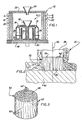
- a mold 10 (Fig. 1) is preheated in a known furnace assembly 12 prior to pouring of molten metal into the mold.
- the known furnace assembly 12 is provided with a refractory outer wall 16 which is surrounded by an induction heating coil 18.
- a graphite susceptor wall 20 is enclosed by the outer wall 16 and is heated by the induction effect of the coil 18.
- the furnace assembly 12 has a top plate 22 with an opening which may be provided with a funnel 24 through which molten metal is poured into the mold 10. It is contemplated that the entire furnace assembly 12 will be disposed within a vacuum furnace.
- the mold 10 has a pouring basin 32 through which molten metal enters a plurality of runners or passages 34 which are connected with a plurality of mold cavities 38 which are disposed in a circular array around the pouring basin 32.
- a cylindrical heat shield 40 may be provided on the inside of the circular array of mold cavities-38.
- the mold 10 is disposed on a copper chill plate 42.
- the chill plate 42 promotes the directional solidification of molten metal in the mold cavities to provide a casting having a columnar grain structure with a grain orientation extending generally parallel to the longitudinal central axes (vertical axes) of the mold cavities 38.
- the furnace 12 and mold 10 could have many different constructions, they have the same general construction as the furnace and mold disclosed in US-A-3,680,625.
- a starter element 50 (see Fig. 2) is positioned in the lower end portion of the mold cavity 38.
- the cylindrical starter element 50 is exposed both to the chill 42 and to the mold cavity 38.
- a lower or bottom side surface 54 of the starter element 50 is disposed in abutting engagement with an upper or top side surface 56 of the chill 42.
- the opposite side surface 58 of the starter element 50 is directly exposed to the mold cavity 38.
- the starter element 50 is formed of a plurality of elongated metal crystals or grains 62 (see Fig. 3) disposed in a side-by-side relationship with longitudinal axes which are substantially perpendicular to the opposite side surfaces 54 and 58 of the starter element which are formed by ends of crystals 62. The large majority of the crystal 62 extend completely through the starter element 50.
- the elongated grains 62 have one transverse end disposed in the circular side surface 54 and the opposite transverse end disposed in the circular side surface 58. A few of the longitudinally extending grains 62 may terminate between the two side surfaces 54 and 58. However, all of the grains which end at the side surface 58 have an opposite end at the side surface 54.
- the elongated grains or crystals 62 have longitudinal axes which extend perpendicular to the side surfaces 54 and 58 and which are disposed in a parallel relationship with a longitudinal central axis 66 (Fig. 2) of the mold cavity 38.
- each of the starter element crystals can effect nucleation of a corresponding longitudinally extending crystal or grain in the molten metal in the mold cavity 38 upon initiation of solidification of the molten metal.
- the elongated crystals which are solidified in the mold cavity 38 have longitudinal axes which extend parallel to the mold axis 66 (Fig.
- the starter element 50 has a fine grain structure so that an array of closely packed and relatively small crystal end portions are provided in the surface 58. This results in the formation of a corresponding number of longitudinally extending crystals or grains in the mold cavity 38. Since these grains nucleate at the end surface 58 of the starter element 50, the molten metal solidifies in the mold cavity 38 with a fine grained structure extending substantially throughout the entire length of the mold cavity and with the grains or elongated crystals extending parallel to the axis 66.
- the mold 10 could be constructed with the cavities 38 to form different types of articles, the mold 10 is advantageously used to form a directionally solidified airfoil 70 (see Fig. 4).
- the airfoil 70 has a leading edge portion 74 and a trailing edge portion 76 which extend between a root end portion 78 and a tip end portion 80 of the airfoil. It should be understood that the configuration of the airfoil 70 has been indicated schematically in Fig. 4 and is merely representative of many known airfoil configurations.
- molten metal is poured into the mold cavity 38.
- the molten metal may be a nickel-base superalloy.
- elongated columnar crystals or grains 86 are nucleated at the end surfaces of the elongated crystals or grains 62 in the starter element 50. This results in the airfoil 70 having a multi-grained elongated crystal structure which corresponds to the multi-grained elongated crystal structure of the starter element 50.
- the elongated grains or crystals 86 in the directionally solidified airfoil 70 have longitudinal axes which extend parallel to the longitudinal axes of the grains 62 in the starter element 50 and to a longitudinal central axis 88 of the airfoil 70 (see Fig. 4). Although a few of the grains or crystals 86 which are nucleated at the upper face 58 of the starter element 50 may terminate part way through the airfoil 70, the vast majority of the grains 86 extend completely through the airfoil 70 from the root end 78 to the tip end 80 of the airfoil. This results in the airfoil 70 having a multi-grained structure throughout its axial length.
- the airfoil 70 may have a leading edge 74 with a twisted and/or bowed configuration
- the elongated crystals 86 extend substantially parallel to the leading edge 74 of the airfoil 70 to enhance the operating characteristics of the airfoil 70 in a known manner.
- Each of the elongated crystals or grains 86 in the airfoil 70 is formed of a plurality of cubic unit cells 94 (Figs. 4 and 5) having the same orientation relative to the longitudinal axis of the crystal.
- the unit cells 94 in each elongated crystal 86 have the same longitudinal orientation relative to the unit cells in adjacent crystals.
- adjacent longitudinally extending crystals 86 have unit cells which have the same longitudinal orientation relative to the longitudinal central axis 88 of the airfoil 70.
- the unit cell the fundamental building block of the crystal, has an atomic arrangement which, when repeated in three dimensions, gives the total structure of the crystal.
- the configuration of the unit cell will vary depending upon the material from which the crystal is formed.
- the unit cell 94 has a face-centered cubic configuration which consists of an atom at each cube corner and one at the center of each face, as depicted in Fig. 4.
- the orientations within each unit cell is specified in terms of its coordinates relative to orthogonal X, Y and Z axes.
- the notation [XYZ] is used to indicate the direction of a line from the origin to a point the coordinates are X, Y and Z.
- brackets are utilized and fractional coordinates are avoided.
- a direction along one of the edges of the cubic cell would also be parallel to one of the three axes and would be denoted as [100], [100], [010], [010], [001], or [001].
- the minus notation above the numeral denotes a negative direction from the origin.
- Each of these directions is said to be equivalent and of the ⁇ 100> family.
- Crystals whose longitudinal axes are vertically aligned and which one of the unit cell axes is also vertically aligned are said to have a [001] orientation, reflecting the convention of denoting the vertical axis as Z.
- the spatial position of the unit cell may be simply visualized as that of a cube lying flat on one of its faces with the longitudinal central axis 88 being perpendicular to the horizontal plane on which the cube rests.
- An extreme form of unit cell orientation occurs in a direction joining the diagonally opposite corners of the cube. This may be visualized as a cube so positioned that one corner makes point contact with a horizontal surface and the other, diagonally opposite, corner falls on a line that both joins the two corners and is perpendicular to the supporting horizontal surface.
- a crystal in which a direction of this family is parallel to the longitudinal central axis 88 is said to have a [111] ] orientation.
- Intermediate between these two extreme orientations of [001] and [111] numerous others are possible. The notation accorded these is well known in the field of crystallography and is not essential to delineating the features of this invention.
- Turbine engine blades and vanes produced by the process of directional solidification wherein metal is solidified in contact with a horizontally disposed copper chill typically involve the use of nickel-base superalloys having a face-centered cubic crystal structure.
- the resulting orientation of elongated crystals in this process [001].
- the side surfaces or faces of the unit cells lie either perpendicular or parallel to the longitudinal central axis 88 of the airfoil 70. This orientation is recognized as superior from the standpoint of thermal fatigue resistance.
- other orientations, particularly the [111] offer the possibility of greatly improved Young's modulus without sacrifice in creep strength. Such a combination of properties may be attractive in applications where particular vibrational and high temperature strength characteristics are desired and thermal fatigue resistance is not a pacing concern.
- the airfoil 70 is cast with each cubic unit cell 94 in the same orientation with respect to the longitudinal axis 88 and with each side surface of a unit cell extending at an acute angle relative to the longitudinal axis of the crystals 86. In one extreme case, this results in a cube diagonal corner to corner orientation of the unit cells denoted above as [111].
- each of the side surfaces of the unit cells 94 extends at an acute angle to the longitudinal axes of the crystals 86 and corresponding longitudinal central axis 88 of the airfoil 70.
- the side surfaces of the unit cells 94 are skewed relative to the longitudinal axes, each cell within an individual crystal has the same orientation.
- Fig. 4 The skewed relationship of the side surfaces of the unit cell 94 relative to the central axis of a crystal 86 has been illustrated schematically in Fig. 4.
- the face centered cubic unit cell 94 has side surfaces 96, 98 and 100 all of which extend at acute angles relative to the longitudinal central axis of the crystal 86.
- the other three side surfaces of the cubic cell also extend at acute angles to the longitudinal axis of the crystal 86.
- the unit cells 94 of the crystals 86 could be oriented with the side surfaces of the cubic cells skewed in many different angles relative to the longitudinal axes of the crystals, in one specific preferred embodiment the [111] direction of the unit cells is parallel to the longitudinal axis of the crystals 86 and corresponding longitudinal central axis 88 of the airfoil 70.
- a unit cell 94 having this orientation has been illustrated schematically in Fig. 5. It should be noted that, although the unit cell 94 is of the face-centered cubic construction, only the lattice points at the corners of the unit cell 94 have been illustrated in Fig. 5, the lattice points at the center of each face being omitted for purposes of clarity of illustration. In Fig. 5, the [111] direction, parallel to the longitudinal axis of the crystals 86 and longitudinal central axis 88 of the airfoil 70, is denoted by the arrow 106.
- each of the side surfaces of the unit cell 94 extends at an acute angle relative to the longitudinal central axis 88 and a line extending between one pair of diagonally opposite corners of the unit cell is parallel to the axis 88.
- a single unit cell 94 has been shown in Figs. 4 and 5, it should be understood that other unit cells of the elongated crystals 86 have the same longitudinal orientation.
- all unit cells also share a common rotational orientation about the longitudinal central axis 88 such that the corresponding side surfaces of all unit cells are parallel.
- other crystals 86 need not share the same rotational orientation, a common longitudinal orientation of [111] exists, imparting within the airfoil 70 a common set of Young's modulus and other mechanical behavior characteristics along the longitudinal central axis 88.
- the extreme cornerwise or skewed, cube diagonal, [111], orientation of the unit cell 94 provides the highest value of Young's modulus. At ambient temperature this value is approximately 44,000,000 psi (724,000,000 kPa) versus approximately 18,000,000 psi (303,000,000 kPa) for an [001] orientation.
- High creep strength has also been reported for the [111] orientation as measured by creep rates and stress rupture lives at elevated temperatures on tests performed using individual crystals of nickel-base superalloys.
- the [111] orientation has been found to provide considerably less primary creep versus that of an [001] orientation and stress rupture lives that are comparable to and, in some cases, superior to those seen with an [001] orientation.
- Using available data for two nickel-base superalloys one published study postulates that the [111] orientation provides the highest creep resistance and rupture lives in comparison with [001] or other orientations.
- the crystals 62 in the starter element 50 have unit cells which are disposed in the same orientation as the unit cells in the crystals 86 of the airfoil 70.
- the unit cells of each crystal 62 in the starter element 50 has a face-centered cubic construction.
- Each of the side surfaces of the cubic unit cells of the starter crystals 62 extends at an acute angle relative to the longitudinal axes of the crystals 62 and relative to the mold axis 66. Since the airfoil 70 is formed of elongated crystals or grains 86 in which each of the unit cells has a [111] orientation, the longitudinally extending starter crystals 62 have unit cells which also have a [111] orientation.
- molten metal is poured into the mold 10.
- the molten metal engages the upper side surface 58 of the starter element 50.
- the starter crystals 62 having unit cells located in the [111] orientation then nucleate airfoil crystals 86 in which the unit cells have a corresponding [111] orientation.
- the orientation of the unit cells 94 in the crystals 86 remains constant. Therefore, all of the unit cells in each of the airfoil crystals 86 have the same [111] orientation.
- the described embodiment of the present invention utilizes a directionally solidified seed or starter element 50 having elongated crystals or grains 62.
- the starter element or seed 50 is oriented in a mold 10 with the longitudinal axes of the crystals 62 in the starter element 50 extending parallel to the preferred direction of grain growth in the mold cavity 38. This results in the initiation or formation of elongated metal crystals or grains 86 in the mold cavity 38 at the starter element 50 with the longitudinal axes of these grains 86 extending parallel to the longitudinal axes of the elongated metal crystals 62 in the starter element.
- the longitudinally extending crystals or grains 86 which are nucleated at the ends of the grains 62 in the starter element have unit cells 94 which are disposed in the same orientation as the unit cells of the starter element.
- a starter element 50 having elongated grains or crystals 62 with unit cells having their side surfaces skewed or extending at an acute angle to the longitudinal axes of the crystals or grains of the starter element longitudinally extending crystals or grains 86 with unit cells having a similar orientation will be formed in the cast article.
- the method the present invention can be used in casting many different types of products, the method is advantageously used to cast airfoils 70 with the elongated crystals or grains 86 having longitudinal axes extending substantially parallel to a leading edge 74 of the airfoil.
Landscapes
- Engineering & Computer Science (AREA)
- Mechanical Engineering (AREA)
- Crystals, And After-Treatments Of Crystals (AREA)
- Turbine Rotor Nozzle Sealing (AREA)
Claims (3)
Applications Claiming Priority (2)
| Application Number | Priority Date | Filing Date | Title |
|---|---|---|---|
| US23964081A | 1981-03-02 | 1981-03-02 | |
| US239640 | 1981-03-02 |
Publications (3)
| Publication Number | Publication Date |
|---|---|
| EP0059549A2 EP0059549A2 (de) | 1982-09-08 |
| EP0059549A3 EP0059549A3 (en) | 1984-04-04 |
| EP0059549B1 true EP0059549B1 (de) | 1987-06-16 |
Family
ID=22903063
Family Applications (1)
| Application Number | Title | Priority Date | Filing Date |
|---|---|---|---|
| EP82300766A Expired EP0059549B1 (de) | 1981-03-02 | 1982-02-16 | Verfahren zum Giessen von Gegenständen |
Country Status (5)
| Country | Link |
|---|---|
| EP (1) | EP0059549B1 (de) |
| JP (1) | JPS57199559A (de) |
| CA (1) | CA1195820A (de) |
| DE (1) | DE3276567D1 (de) |
| IL (1) | IL65014A0 (de) |
Cited By (6)
| Publication number | Priority date | Publication date | Assignee | Title |
|---|---|---|---|---|
| EP0126550A1 (de) * | 1983-04-21 | 1984-11-28 | Aeplc | Gegossene Gegenstände mit gerichteter Erstarrung |
| US4580613A (en) * | 1982-08-05 | 1986-04-08 | Howmet Turbine Components Corporation | Method and mold for casting articles having a predetermined crystalline orientation |
| US4612969A (en) * | 1983-04-27 | 1986-09-23 | Howmet Turbine Components Corporation | Method of and apparatus for casting articles with predetermined crystalline orientation |
| WO1999004612A1 (en) | 1997-07-25 | 1999-02-04 | Arboc Limited | A bale wrapping machine |
| US6343641B1 (en) | 1999-10-22 | 2002-02-05 | General Electric Company | Controlling casting grain spacing |
| US10829831B2 (en) | 2012-08-28 | 2020-11-10 | Raytheon Technologies Corporation | High elastic modulus shafts and method of manufacture |
Families Citing this family (4)
| Publication number | Priority date | Publication date | Assignee | Title |
|---|---|---|---|---|
| US5577547A (en) * | 1994-04-28 | 1996-11-26 | Precision Castparts Corp. | Method of casting a metal article |
| WO1998005450A1 (de) * | 1996-08-06 | 1998-02-12 | Siemens Aktiengesellschaft | Verfahren und einrichtung zur gerichteten erstarrung einer schmelze |
| US7338259B2 (en) * | 2004-03-02 | 2008-03-04 | United Technologies Corporation | High modulus metallic component for high vibratory operation |
| FR2985924B1 (fr) * | 2012-01-24 | 2014-02-14 | Snecma | Carapace pour la fabrication par moulage a cire perdue d'elements aubages de turbomachine d'aeronef, comprenant des ecrans formant accumulateurs de chaleur |
Citations (3)
| Publication number | Priority date | Publication date | Assignee | Title |
|---|---|---|---|---|
| GB1256348A (en) * | 1969-06-27 | 1971-12-08 | United Aircraft Corp | Directionally solidified castings |
| GB1426805A (en) * | 1972-05-17 | 1976-03-03 | United Aircraft Corp | Unidirectionally solidified alloy articles |
| GB2037200A (en) * | 1978-12-13 | 1980-07-09 | United Technologies Corp | Epitaxial solidification |
Family Cites Families (2)
| Publication number | Priority date | Publication date | Assignee | Title |
|---|---|---|---|---|
| GB870213A (en) * | 1956-09-20 | 1961-06-14 | Gen Electric | Apparatus for and method of casting grain-oriented ingots |
| JPS514186A (en) * | 1974-12-20 | 1976-01-14 | Nippon Soda Co | 2*33 jihidoro 4hh1*33 benzookisajinkeikagobutsuno seizohoho |
-
1982
- 1982-02-15 IL IL65014A patent/IL65014A0/xx unknown
- 1982-02-16 DE DE8282300766T patent/DE3276567D1/de not_active Expired
- 1982-02-16 EP EP82300766A patent/EP0059549B1/de not_active Expired
- 1982-03-01 JP JP57032188A patent/JPS57199559A/ja active Pending
- 1982-03-01 CA CA000397293A patent/CA1195820A/en not_active Expired
Patent Citations (3)
| Publication number | Priority date | Publication date | Assignee | Title |
|---|---|---|---|---|
| GB1256348A (en) * | 1969-06-27 | 1971-12-08 | United Aircraft Corp | Directionally solidified castings |
| GB1426805A (en) * | 1972-05-17 | 1976-03-03 | United Aircraft Corp | Unidirectionally solidified alloy articles |
| GB2037200A (en) * | 1978-12-13 | 1980-07-09 | United Technologies Corp | Epitaxial solidification |
Cited By (6)
| Publication number | Priority date | Publication date | Assignee | Title |
|---|---|---|---|---|
| US4580613A (en) * | 1982-08-05 | 1986-04-08 | Howmet Turbine Components Corporation | Method and mold for casting articles having a predetermined crystalline orientation |
| EP0126550A1 (de) * | 1983-04-21 | 1984-11-28 | Aeplc | Gegossene Gegenstände mit gerichteter Erstarrung |
| US4612969A (en) * | 1983-04-27 | 1986-09-23 | Howmet Turbine Components Corporation | Method of and apparatus for casting articles with predetermined crystalline orientation |
| WO1999004612A1 (en) | 1997-07-25 | 1999-02-04 | Arboc Limited | A bale wrapping machine |
| US6343641B1 (en) | 1999-10-22 | 2002-02-05 | General Electric Company | Controlling casting grain spacing |
| US10829831B2 (en) | 2012-08-28 | 2020-11-10 | Raytheon Technologies Corporation | High elastic modulus shafts and method of manufacture |
Also Published As
| Publication number | Publication date |
|---|---|
| DE3276567D1 (en) | 1987-07-23 |
| JPS57199559A (en) | 1982-12-07 |
| EP0059549A3 (en) | 1984-04-04 |
| EP0059549A2 (de) | 1982-09-08 |
| IL65014A0 (en) | 1982-04-30 |
| CA1195820A (en) | 1985-10-29 |
Similar Documents
| Publication | Publication Date | Title |
|---|---|---|
| Versnyder et al. | The development of columnar grain and single crystal high temperature materials through directional solidification | |
| KR100622719B1 (ko) | 초합금 주조 제품, 방향성 응고 단결정 초합금 제품, 가스 터빈, 터빈 블레이드, 노즐, 버킷, 베인 및 에어포일과, 방향성 응고 주상 단결정 제품, 다결정 제품 및 그 제조 방법 | |
| RU2647422C2 (ru) | Оболочковая форма, имеющая теплозащитный экран | |
| EP0475428B1 (de) | Gasturbine, für diese Gasturbine verwendete Schaufel und Verfahren zur Herstellung dieser Schaufel | |
| US4612969A (en) | Method of and apparatus for casting articles with predetermined crystalline orientation | |
| US3857436A (en) | Method and apparatus for manufacturing monocrystalline articles | |
| JPH0255144B2 (de) | ||
| JPS58181790A (ja) | 単結晶物品及びその鋳造方法 | |
| EP1093872B1 (de) | Bestimmung des Kornabstands bei gerichtet erstarrten Gussstücken | |
| EP0059549A2 (de) | Verfahren zum Giessen von Gegenständen | |
| US4609029A (en) | Method of reducing casting time | |
| EP0100150A2 (de) | Metallische einkristalline Luftschaufel | |
| US6383448B1 (en) | Nickel-based superalloy | |
| EP0711215B1 (de) | Verfahren zum giessen eines metallteiles | |
| CA2724387A1 (en) | High thermal gradient casting with tight packing of directionally solidified casting | |
| EP0066971A2 (de) | Verfahren zum Giessen eines Gegenstandes | |
| US6568456B1 (en) | Method for manufacture of a directionally solidified columnar grained article | |
| JPH0119992B2 (de) | ||
| EP0059550B1 (de) | Verfahren zum Giessen | |
| CN115673243B (zh) | 一种单晶导向叶片及其精密铸造方法 | |
| JPH04231170A (ja) | プラットホームを有する超合金製タービンエンジン羽根を単結晶凝固により鋳造するための鋳型 | |
| RU2080209C1 (ru) | Устройство для получения монокристальных отливок | |
| RU2201843C2 (ru) | Керамическая форма для литья изделий с направленной и монокристальной структурой | |
| JPS58370A (ja) | 物品の鋳造法 | |
| RU2179087C1 (ru) | Устройство для литья монокристаллических отливок |
Legal Events
| Date | Code | Title | Description |
|---|---|---|---|
| PUAI | Public reference made under article 153(3) epc to a published international application that has entered the european phase |
Free format text: ORIGINAL CODE: 0009012 |
|
| AK | Designated contracting states |
Designated state(s): BE CH DE FR GB IT SE |
|
| 17P | Request for examination filed |
Effective date: 19820908 |
|
| PUAL | Search report despatched |
Free format text: ORIGINAL CODE: 0009013 |
|
| AK | Designated contracting states |
Designated state(s): BE CH DE FR GB IT LI SE |
|
| GRAA | (expected) grant |
Free format text: ORIGINAL CODE: 0009210 |
|
| RAP1 | Party data changed (applicant data changed or rights of an application transferred) |
Owner name: PCC AIRFOILS, INC |
|
| AK | Designated contracting states |
Kind code of ref document: B1 Designated state(s): BE CH DE FR GB IT LI SE |
|
| ITF | It: translation for a ep patent filed | ||
| REF | Corresponds to: |
Ref document number: 3276567 Country of ref document: DE Date of ref document: 19870723 |
|
| ET | Fr: translation filed | ||
| PG25 | Lapsed in a contracting state [announced via postgrant information from national office to epo] |
Ref country code: SE Effective date: 19880217 |
|
| PG25 | Lapsed in a contracting state [announced via postgrant information from national office to epo] |
Ref country code: LI Effective date: 19880229 Ref country code: CH Effective date: 19880229 |
|
| PLBE | No opposition filed within time limit |
Free format text: ORIGINAL CODE: 0009261 |
|
| STAA | Information on the status of an ep patent application or granted ep patent |
Free format text: STATUS: NO OPPOSITION FILED WITHIN TIME LIMIT |
|
| 26N | No opposition filed | ||
| PG25 | Lapsed in a contracting state [announced via postgrant information from national office to epo] |
Ref country code: FR Free format text: LAPSE BECAUSE OF NON-PAYMENT OF DUE FEES Effective date: 19881028 |
|
| REG | Reference to a national code |
Ref country code: CH Ref legal event code: PL |
|
| PG25 | Lapsed in a contracting state [announced via postgrant information from national office to epo] |
Ref country code: DE Effective date: 19881101 |
|
| GBPC | Gb: european patent ceased through non-payment of renewal fee | ||
| PG25 | Lapsed in a contracting state [announced via postgrant information from national office to epo] |
Ref country code: GB Free format text: LAPSE BECAUSE OF NON-PAYMENT OF DUE FEES Effective date: 19881121 |
|
| REG | Reference to a national code |
Ref country code: FR Ref legal event code: ST |
|
| PG25 | Lapsed in a contracting state [announced via postgrant information from national office to epo] |
Ref country code: BE Effective date: 19890228 |
|
| BERE | Be: lapsed |
Owner name: PCC AIRFOILS INC Effective date: 19890228 |
|
| EUG | Se: european patent has lapsed |
Ref document number: 82300766.1 Effective date: 19880927 |