EP0059612A2 - Procédé, outil et machine de brochage pour fabriquer des éléments en forme de volutes pour des appareils comprenant ces éléments - Google Patents
Procédé, outil et machine de brochage pour fabriquer des éléments en forme de volutes pour des appareils comprenant ces éléments Download PDFInfo
- Publication number
- EP0059612A2 EP0059612A2 EP82300976A EP82300976A EP0059612A2 EP 0059612 A2 EP0059612 A2 EP 0059612A2 EP 82300976 A EP82300976 A EP 82300976A EP 82300976 A EP82300976 A EP 82300976A EP 0059612 A2 EP0059612 A2 EP 0059612A2
- Authority
- EP
- European Patent Office
- Prior art keywords
- broaching
- involute
- scroll member
- wrap
- accordance
- Prior art date
- Legal status (The legal status is an assumption and is not a legal conclusion. Google has not performed a legal analysis and makes no representation as to the accuracy of the status listed.)
- Granted
Links
Images


Classifications
-
- B—PERFORMING OPERATIONS; TRANSPORTING
- B23—MACHINE TOOLS; METAL-WORKING NOT OTHERWISE PROVIDED FOR
- B23D—PLANING; SLOTTING; SHEARING; BROACHING; SAWING; FILING; SCRAPING; LIKE OPERATIONS FOR WORKING METAL BY REMOVING MATERIAL, NOT OTHERWISE PROVIDED FOR
- B23D37/00—Broaching machines or broaching devices
- B23D37/22—Broaching machines or broaching devices for special purposes
-
- F—MECHANICAL ENGINEERING; LIGHTING; HEATING; WEAPONS; BLASTING
- F04—POSITIVE - DISPLACEMENT MACHINES FOR LIQUIDS; PUMPS FOR LIQUIDS OR ELASTIC FLUIDS
- F04C—ROTARY-PISTON, OR OSCILLATING-PISTON, POSITIVE-DISPLACEMENT MACHINES FOR LIQUIDS; ROTARY-PISTON, OR OSCILLATING-PISTON, POSITIVE-DISPLACEMENT PUMPS
- F04C18/00—Rotary-piston pumps specially adapted for elastic fluids
- F04C18/02—Rotary-piston pumps specially adapted for elastic fluids of arcuate-engagement type, i.e. with circular translatory movement of co-operating members, each member having the same number of teeth or tooth-equivalents
-
- F—MECHANICAL ENGINEERING; LIGHTING; HEATING; WEAPONS; BLASTING
- F04—POSITIVE - DISPLACEMENT MACHINES FOR LIQUIDS; PUMPS FOR LIQUIDS OR ELASTIC FLUIDS
- F04C—ROTARY-PISTON, OR OSCILLATING-PISTON, POSITIVE-DISPLACEMENT MACHINES FOR LIQUIDS; ROTARY-PISTON, OR OSCILLATING-PISTON, POSITIVE-DISPLACEMENT PUMPS
- F04C2/00—Rotary-piston machines or pumps
- F04C2/02—Rotary-piston machines or pumps of arcuate-engagement type, i.e. with circular translatory movement of co-operating members, each member having the same number of teeth or tooth-equivalents
-
- F—MECHANICAL ENGINEERING; LIGHTING; HEATING; WEAPONS; BLASTING
- F04—POSITIVE - DISPLACEMENT MACHINES FOR LIQUIDS; PUMPS FOR LIQUIDS OR ELASTIC FLUIDS
- F04C—ROTARY-PISTON, OR OSCILLATING-PISTON, POSITIVE-DISPLACEMENT MACHINES FOR LIQUIDS; ROTARY-PISTON, OR OSCILLATING-PISTON, POSITIVE-DISPLACEMENT PUMPS
- F04C2230/00—Manufacture
- F04C2230/10—Manufacture by removing material
-
- F—MECHANICAL ENGINEERING; LIGHTING; HEATING; WEAPONS; BLASTING
- F04—POSITIVE - DISPLACEMENT MACHINES FOR LIQUIDS; PUMPS FOR LIQUIDS OR ELASTIC FLUIDS
- F04C—ROTARY-PISTON, OR OSCILLATING-PISTON, POSITIVE-DISPLACEMENT MACHINES FOR LIQUIDS; ROTARY-PISTON, OR OSCILLATING-PISTON, POSITIVE-DISPLACEMENT PUMPS
- F04C2230/00—Manufacture
- F04C2230/20—Manufacture essentially without removing material
- F04C2230/21—Manufacture essentially without removing material by casting
-
- Y—GENERAL TAGGING OF NEW TECHNOLOGICAL DEVELOPMENTS; GENERAL TAGGING OF CROSS-SECTIONAL TECHNOLOGIES SPANNING OVER SEVERAL SECTIONS OF THE IPC; TECHNICAL SUBJECTS COVERED BY FORMER USPC CROSS-REFERENCE ART COLLECTIONS [XRACs] AND DIGESTS
- Y10—TECHNICAL SUBJECTS COVERED BY FORMER USPC
- Y10T—TECHNICAL SUBJECTS COVERED BY FORMER US CLASSIFICATION
- Y10T29/00—Metal working
- Y10T29/49—Method of mechanical manufacture
- Y10T29/49316—Impeller making
- Y10T29/4932—Turbomachine making
- Y10T29/49325—Shaping integrally bladed rotor
-
- Y—GENERAL TAGGING OF NEW TECHNOLOGICAL DEVELOPMENTS; GENERAL TAGGING OF CROSS-SECTIONAL TECHNOLOGIES SPANNING OVER SEVERAL SECTIONS OF THE IPC; TECHNICAL SUBJECTS COVERED BY FORMER USPC CROSS-REFERENCE ART COLLECTIONS [XRACs] AND DIGESTS
- Y10—TECHNICAL SUBJECTS COVERED BY FORMER USPC
- Y10T—TECHNICAL SUBJECTS COVERED BY FORMER US CLASSIFICATION
- Y10T409/00—Gear cutting, milling, or planing
- Y10T409/40—Broaching
- Y10T409/400175—Process
Definitions
- This invention relates to scroll-type apparatus and more particularly to the construction of the scroll members used therein.
- spiral pumps compressors and expanders wherein two interfitting spiroidal or involute spiral elements of like pitch are mounted on separate end plates.
- These spiral elements are angularly and radially offset to contact one another along at least one pair of line contacts such as between spiral curved surfaces.
- a pair of line contacts will lie approximately upon one radius drawn outwardly from the central region of the scrolls.
- the fluid volume so formed therefore extends all the way around the central region of the scrolls and comprises one or more fluid pockets, the angular position of which varies with relative orbiting of the spiral centers. All of these pockets maintain the same relative angular position; and as the contact lines shift along the scroll surfaces, the pockets experience a change in volume.
- the resulting zones of lowest and highest pressures are connected to fluid ports.
- Radial sealing of the fluid pockets i.e., sealing across the surface of the involute wraps to prevent leakage from a pocket of higher pressure to an adjacent pocket of lower pressure is preferably controlled through the use of axial compliance/sealing means such as detailed in United States Patents 3,994,636 and 4,199,308 and in United States, application Serial No. 233,915, filed February 12, 1981.
- the use of such sealing means eliminates the need for: the lapping of the wrap and end plate contacting surfaces.
- effective sealing requires that along its entire length the involute wrap is joined at its base to the end plate to define a right angle or other suitable configuration to permit the required contact with the opposing end of the complementary scroll member when assembled in an operational scroll apparatus. Effective sealing also requires the accurate dimensioning and finishing of the wrap flanks and the end plate surface.
- a suitable mass production technique for scroll components should involve minimum machining; and it should provide components which meet the stringent requirements for dimensional accuracy and finishing associated with efficient scroll operation.
- There are two basic constructional alternatives for fabricating scroll members namely, forming them from an integrally cast involute and end plate or forming the involute and end plate separately and joining them into a finished scroll member.
- Precision die casting of a scroll member either as an integral element or as a separate involute wrap and end plate, followed by one or another finishing techniques eliminates the disadvantages of having to rely solely,on milling of the involute wrap.
- One such finishing technique is coining, or cold forming in a closed die; and it is described in our copending European Patent Application No. 82 300975.8 filed concurrently herewith (corresponding to United States Patent Application No. 239564, filed 2nd March 1981).
- United States Patent 3,994,365 there is disclosed an alternative to the machining of the wrap flanks and end plate surfaces and to the combined techniques of precision casting and coining.
- This method comprises the steps of forming in the surface of the end plate an involutely configured channel; forming a reentrant groove in one side wall of the channel along its length; providing the involute wrap sized and configured to seat in the channel and having a surface configured to at least partially engage the reentrant groove along its length; seating the wrap into the channel thereby to define a locking space between the flank of the wrap and the other side wall of the channel; and locking the wrap in the channel into fixed engagement with the end plate.
- a further object is to provide tooling of the character described which achieves the dimensional accuracy and finishing of the flanks of the involute wrap through broaching.
- a method of fabricating a scroll member comprising the steps of providing a precision preformed scroll member as an element having affixed to an end plate an involute wrap having its inner and outer flanks joined to the end plate along the base of the involute wrap; forming reentrant corners between the surface of the end plate and the inner and outer flank surfaces joining the involute wrap to the end plate;broaching the inner and outer flanks of the involute wrap axially toward the surface of the end plate to attain a predetermined thickness of said involute wrap and a radial spacing between the turns thereof, the reentrant corners providing clearance for chips resulting from the broaching.
- the inner and outer flanks may be broached separately or simultaneously.
- the broach or scroll member is angularly indexed relatively to the other, thus providing sequential engagement of the cutting edge with the flank until the desired dimensions and finish are attained.
- a series of broaches are used.
- a broaching tool for fabricating a scroll member .formed as an involute wrap rigidly affixed to an end plate, comprising an involute blade cutter terminating in a tooth running along essentially the full length of at least one side of the blade cutter, the tooth having a cutting edge with the same involute contour and pitch of the finally broached involute wrap or the scroll member.
- a broaching machine for fabricating a scroll member formed as an involute wrap rigidly affixed to an end plate, comprising in combination a broaching tool comprising an involute blade cutter terminating in a tooth running along essentially the full length of at least one side of the blade cutter, the tooth having a cutting edge with the same involute contour and pitch of the finally broached involute wrap of the scroll member; broaching tool support means; workpiece support means arranged to support the scroll member in a predetermined position relative to the broaching tool; force applying means for effecting relative vertical motion between the broaching tool support means and the workpiece support means along the axis of the scroll member whereby the cutting edge engages and broaches the flank of the wrap.
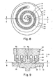
- Figs. 1 and 2 illustrate the basic design of a typical scroll member suitable for use in any of the scroll apparatus described in the previously listed United States Patents.
- the basic construction of any scroll member 10 comprises an end plate 11 and an involute wrap 12 affixed thereto.
- the wrap is hereinafter for convenience referred to as being "involute", i.e., configured as an involute of a circle.
- the wraps may have, for example, the configuration of an arc of a circle or any other suitable shape.
- the scroll member 10 of Figs. 1 and 2 is suitable as the orbiting member of a scroll apparatus and is therefore shown to have a stub shaft 13. It will be appreciated that requirements for such other features as keyways, ports, peripheral walls, special bearing surfaces and the like may vary from one scroll apparatus to another and that the various configurations and/or surface modifications required to provide such features may be provided through the use of well-known fabrication techniques.
- a scroll apparatus is made up of complentary scroll members having facing end plates with angularly and radially offset involute wraps of like pitch.
- the orbiting of one of these scroll members angularly and radially offset from the other defines fluid pockets which in the case of a compressor or expander decrease in pressure radially outward from the machine axis.
- the contacting of wrap flanks 14, affixed to the complementary end plate 15 of a stationary scroll member defines fluid pockets 16 and 17 in which P 16 >P 17 .
- the dimensional accuracy and precision of finishing which must be attained in the manufacture of highly efficient scroll members may be illustrated using as exemplary one having involute wraps which are 0.187 inch (0.475 cm) thick and 1.25 inches (3.175 cms) high.
- the distances from the centerline 18 to the inner and outer wrap flank surfaces should be within 0.001 inch (0.025 mm).
- Fig. 3 illustrates the formation of an adequate chip clearance space and the finishing of the end plate surface preparatory to the broaching of the inner and outer flank walls of the involute wrap. It should be noted that Fig. 3, as well as Fig. 4 described below, is not drawn to scale and that some dimensions are highly exaggerated for purposes of illustration.
- FIG. 3A there is shown in that drawing a fragmentary cross section of two adjacent turns 25 and 26 of an involute wrap integral with an end plate 27 having a contacting surface 28.
- involute turn 25 will be seen to have an inner flank wall 30 and involute turn 26 an outer flank wall 31.
- Between walls 30 and 31 is working space 32 into which is fit the involute wrap of the complementary mating scroll member as illustrated in Fig. 2.
- walls 30 and 31 are shown to be formed with inward flares and to have fillets with end plate surface 28 which represent dead corners 33 and 34.
- the scroll member Since in its preferred configuration the scroll member has an involute with.flank walls which are perpendicular to the end plate surface the desired final configuration for the flanks is shown by the dotted lines 28a, 30a and 31a. This then means that the materal 35 defined between the actual precision preform (e.g., cast) form defined by walls 28, 30 and 31 and the final required form defined by walls 28a, 30a and 31a, must be removed.
- the actual precision preform e.g., cast
- a milling cutter 38 (Fig. 3B) is used to cut reentrant corners 39 and 40 (Fig. 3C) along the involute flank walls 30 and 31 and to finish end plate surface 28a.
- the milling is, of course, begun at the outboard end of the involute wrap 12 (Fig. 1) and finished at the inboard end. If desired, machining of the tip or contact surface of the involute wrap to a desired dimension and finish may be performed simultaneously with the milling of reentrant cor - ners 39 and 40.
- the width of the cut of milling cutter 38 is preferably equal to the finished spacing desired between flank walls 30a and 31a.
- this width may be slightly greater than the desired spacing and hence it can be said that the reentrant corners essentially represent the predetermined finished dimensions of the wrap thickness and radial spacing between the involute turns. As will be shown in connection with Fig. 4, these reentrant corners 39 and 40 provide the necessary clearance for the chips resulting from the broaching.
- Fig. 4 shows the progressive broaching of a flank surface, e.g., wall 30 to attain wall 30a.
- the broach is so arranged as described below, so that in the first axially downward stroke, indicated by arrow 45, the tooth 46 of the broach contacts the wall as indicated by the dotted line position (Fig. 4A).
- Fig. 4A shows the dotted line position
- the single-sided broach 54 of Fig. 5 comprises an involute support 55 which terminates in a blade cutter 56 with a single cutting edge, i.e., tooth 57.
- Involute support 55 extends from a subpress member 58.
- the single-sided broaching tool of Fig. 5, having tooth 57 around the inner side of blade cutter 56, is designed to broach the outer flank wall of an involute wrap.
- a single-sided broaching tool may be made having a cutting edge, i.e., tooth around the outer side for broaching the inner flank wall.
- the cutting edge has the same involute contour and involute pitch as that required of the finally broached wrap of the scroll member.
- involute pitch is defined herein as the numerical difference in the radii of consecutive turns of the outer (or inner) wrap flank walls. These radii are lines drawn tangent to the generating radius.
- the double-sided broaching tool 59 of Fig. 6 comprises an involute support 60 which terminates in a blade cutter 61 having teeth 62 and 63 with cutting edges disposed on opposite sides of the cutter. Like the single-side tool of Fig. 5, the double-sided tool of Fig. 6 extends from a subpress member 58. The opposed cutting edges of the double-sided broach also have the same involute contour and pitch as that required of the finally broached wrap. The operation of this embodiment of the broaching tool is described below in conjunction with Figs. 18-22.
- the broaching tools in keeping with well known tool fabrication practice, may be formed of such material as hardened tool steel by any suitable technique. embodying
- the tools this invention achieve push broaching and they are mounted on machines of the press type as shown in Fig. 7 which illustrates, partially in cross section, a machine for using the tool of Fig. 5.
- the preformed scroll member 10, such as that of Figs. 1 and 2 is set in a subpress member 66 configured to seat scroll member 10 so that end plate surface 20 is flush with surface 67.
- Scroll member 10 is located and held in workpiece subpress 66 by means of several positioning pins 68.
- subpress 66 is mounted, through aligning pins 70, to an indexing table 71 which is arranged to be rotated with respect to press member 72.
- indexing table 71 may be eliminated in using the broaching tool of Fig. 6, in which case the scroll member subpress 66 is positioned and held directly to press member 72.
- the tool subpress 58 associated with the broaching tool shown-generally at 73 in Fig. 7, is affixed by appropriate means (not shown) to press member 74.
- one of the press members is driven vertically, as indicated by the arrow, by hydraulical means, by screw, rack, crank or the like.
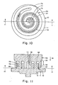
- Figs. 8-13 are presented to illustrate the operation of the single-sided broach of Fig. 5 in broaching the outer flank wall 75 of scroll member 10 constructed as shown in Figs. 1 and 2.
- the same reference numbers are used to identify the same elements in Figs. 1, 2, 5 and 8-13.
- broach 54 preferably has an enlarged outer section 76 and enlarged inner section 77 to impart strength and rigidity to it. Through inner section 77 is drilled a fluid passage 78 for introducing a cutting fluid to carry away the chips formed.
- the drawings in Figs. 8-17 do not detail the reentrant corners shown in Figs. 3 and 4 or any variations in involute thickness. Rather, these drawings illustrate the indexing of the scroll member relative'to the broach and the manner in which the broach achieves the final desired configuration of the scroll member.
- broaching is begun by rotating the indexing table (Fig. 7) so that the outer flank 75 of involute 12 clears the tooth 57 and inner flank 79 clears the outer surface 76 of broach involute 55.
- Angular indexing the scroll member 10 in a counterclockwise direction then brings the tooth 57 into contact with involute flank 75 somewhere along its height as shown in Figs. 10 and 11. (See also Fig. 4).
- Vertically stroking the broach several times in this initially indexed position of the scroll member develops a chip 80 as previously described.
- the unidirectional broaching is indicated by arrow 81.
- Scroll member 10 is then further indexed in a counterclosewise direction through a predetermined angle and the vertical stroking is repeated until the desired configuration of the outer involute flank 75 is attained as shown in Figs. 12 and 13.
- rotation of the scroll member, or alternatively of the broaching tool in the opposite direction winds them together forcing the cutting edge of the broach tooth to continually make contact with the flank being broached.
- rotation of the indexing table, or the tool, in the direction opposite to that used in broaching returns the scroll member, relative to the broach, to a position where it may be removed from the subpress 66 (Fig. 7).
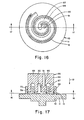
- Figs. 14-17 illustrate the manner in which inner flank 79 of involute wrap 12 is broached with a broaching tool 85 comprising an involute support 86, a blade cutter 87 and outwardly directed tooth 88, all of which are integral with or affixed to a subpress member 89.
- the enlarged inner section 90 has a fluid passage 91 for introducing a cutting liquid to remove chips.
- broaching with tool 85 is begun by indexing scroll member 10 (or alternatively tool 85) so that tooth 88 clears the surface of inner flank 79 and the opposing involute surface 93 of involute support 86 clears outer flank 75 of involute wrap 12.
- the scroll member is indexed with relation to the broaching tool, then it is turned in a clockwise direction and it is wound until contact is made between tooth 88 and flank surface 79. After each step of indexing through a predetermined angle, the broach is vertically stroked to form chip 95, and this is continued until the final configuration for flank surface 79 is attained (Figs. 16 and 17) . Again as in finishing the outer flank, the broach is removed after rotating the scroll member in a counterclockwise direction.
- the indexing angle between strokings is used to control the depth of the cut made.
- the optimum depth of cut will in turn depend upon the material from which the involute wrap is formed, the softer the material the greater the depth of cut per stroke and the greater the indexing angle can be. It is, of course, well within the skill of the art to make such determinations for the fabrication of any one particular scroll member. As the broaching tool wears and dulls, it may, of course, be resharpened. Its subsequent use requires only the resetting of the initial angular position to account for its slight change in size and this is readily done by ancular indexing.
- the use of the single-sided broaching tools can in some cases give rise to finished scroll members with less than the desired finished dimensions due to the potentially large lateral force exerted on the broach and workpiece during broaching on that part which has an eccentric contour to the preformed involute surface. This problem can be most apparent in the outer regions of the involute where the curvature and lateral stiffness are minimum. Such deflections can be minimized by proper choice of indexing angle and by using single-sided broaching for the stiffer scroll member materials and for the thicker involute wraps.
- a double-sided broach capable of cutting both sides of the involute simultaneously and thereby minimizing lateral forces on the broach and the workpiece.
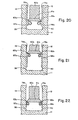
- a broach is illustrated in Figs. 6, 18 and 19.
- the broach 59 is sized and configured so that when aligned for broaching, the opposed teeth 62 and 63 can make initial contact with the preformed flank surfaces 79 and 75, respectively. It will, of course, be appreciated that such contact with teeth 62 and 63 will not necessarily at first be made at the same level along the entire length of involute wrap 12, or that it will be made at all along some sections of the entire length.
- Vertically stroking broaching tool 59 gives rise to chips 97 and 98 which are carried away by cutting oil introduced through liquid passage 99.
- broaches in sequence may be used to effect a rough cut, then an intermediate cut and finally a finish cut.
- a set of such broaches is, of course, not limited to three.
- the amount of material removed in each of these cuts is progressively decreased so that the finish cut is used primarily to accomplish final sizing and finishing of the scroll member.
- Figs. 20-21 illustrate in exaggerated, fragmentary cross sections the use of three such broaches in sequence.
- the centerline of the scroll member being broached lies to the right of the figures and the reference numerals, where appropriate, are followed by "a", "b” or “c” to designate the rough, intermediate and finish cuts, respectively. It will be seen that by incrementally increasing the distance between opposing teeth 62 and 63 the desired finish and dimensions can be attained (Fig. 22).
- the radial distance between involute turns decreases. Stated another way, the thickness of the involute wrap increases.
- the relief angles on the broach cutting surfaces are small enougn so that a given broach can be sharpened many times before the deviation in radial distance or involute thickness is of sufficient magnitude to require changing the broach.
- the broach becomes increasingly smaller due to sharpening, it can be progressively used for the cuts immediately preceding that for which it had been used, thus maximizing tool life.
- a slight but uniform variation in dimension throughout the scroll member is permissible.
- the broaching method and tools of this invention are applied to fabricating scroll members to predetermined dimensions and finish beginning with precision preformed parts.
- the precision preforming may be accomplished using such well-known techniques as precision casting (die or lost wax casting), casting followed by cold forging, impact forming and the like.
- the scroll member to be broached must have the involute wrap rigidly and permanently affixed to the end plate, it may be formed originally as separate elements which are then joined by any suitable method such as, for example, those described incur U. S. Patent 3,994,635.and our previoizsly mentioned copending applications.
- the broaching method is preferably used for removing about 0.005 to about 0.020 inch (about 0.125 to about 0.5 mm) of material from the involute flanks and it may be applied to scroll members formed of aluminum, steel or cast iron, for example. Broaching is capable of reducing the involute surface machining costs associated with fabricating scroll members and facilitates mass production of these components without sacrificing dimensional accuracy or surface finish requirements.
Landscapes
- Engineering & Computer Science (AREA)
- Mechanical Engineering (AREA)
- General Engineering & Computer Science (AREA)
- Rotary Pumps (AREA)
- Milling, Broaching, Filing, Reaming, And Others (AREA)
Priority Applications (1)
| Application Number | Priority Date | Filing Date | Title |
|---|---|---|---|
| AT82300976T ATE21640T1 (de) | 1981-03-02 | 1982-02-25 | Verfahren, raeumer und raeummaschine zum herstellen von schneckengliedern fuer schneckenartige vorrichtungen. |
Applications Claiming Priority (2)
| Application Number | Priority Date | Filing Date | Title |
|---|---|---|---|
| US06/239,414 US4512066A (en) | 1981-03-02 | 1981-03-02 | Method of fabricating scroll members |
| US239414 | 1999-01-28 |
Publications (3)
| Publication Number | Publication Date |
|---|---|
| EP0059612A2 true EP0059612A2 (fr) | 1982-09-08 |
| EP0059612A3 EP0059612A3 (en) | 1984-05-02 |
| EP0059612B1 EP0059612B1 (fr) | 1986-08-27 |
Family
ID=22902027
Family Applications (1)
| Application Number | Title | Priority Date | Filing Date |
|---|---|---|---|
| EP82300976A Expired EP0059612B1 (fr) | 1981-03-02 | 1982-02-25 | Procédé, outil et machine de brochage pour fabriquer des éléments en forme de volutes pour des appareils comprenant ces éléments |
Country Status (5)
| Country | Link |
|---|---|
| US (1) | US4512066A (fr) |
| EP (1) | EP0059612B1 (fr) |
| JP (1) | JPS57149030A (fr) |
| AT (1) | ATE21640T1 (fr) |
| DE (1) | DE3272802D1 (fr) |
Cited By (5)
| Publication number | Priority date | Publication date | Assignee | Title |
|---|---|---|---|---|
| DE3321322A1 (de) * | 1982-06-16 | 1984-01-26 | Hitachi, Ltd., Tokyo | Verfahren und vorrichtung zur bearbeitung eines spiralelements |
| WO1989008522A1 (fr) * | 1988-03-11 | 1989-09-21 | Bishop Arthur E | Procede d'usinage d'elements spirales |
| CN101963474A (zh) * | 2010-09-15 | 2011-02-02 | 广州大学 | 一种平面三维沸腾结构及其加工方法 |
| EP2141362A4 (fr) * | 2007-03-30 | 2015-01-07 | Daikin Ind Ltd | Élément en spirale, son procédé de fabrication, mécanisme de compression et compresseur à spirales |
| CN110587229A (zh) * | 2019-09-04 | 2019-12-20 | 江西佳时特精密机械有限责任公司 | 涡旋盘类零件加工方法 |
Families Citing this family (26)
| Publication number | Priority date | Publication date | Assignee | Title |
|---|---|---|---|---|
| US4696084A (en) * | 1985-06-14 | 1987-09-29 | Mitsubishi Jukogyo Kabushiki Kaisha | Method for forming scroll members used in a scroll type fluid machine |
| US4693813A (en) * | 1985-07-30 | 1987-09-15 | Toyota Jidosha Kabushiki Kaisha | Method of broaching outer periphery of lobe-type rotor of roots-type fluid machine, and broaching cutter used in the method |
| JPH0729622B2 (ja) * | 1988-06-11 | 1995-04-05 | マツダ株式会社 | 車体組立方法 |
| US5122040A (en) * | 1990-08-03 | 1992-06-16 | American Standard Inc. | Scroll member and method of forming a scroll member |
| US5103558A (en) * | 1990-08-24 | 1992-04-14 | Tecumseh Products Company | Method and apparatus for machining scroll wraps |
| US5470305A (en) | 1993-04-19 | 1995-11-28 | Stryker Corporation | Irrigation handpiece with built in pulsing pump |
| US6746419B1 (en) * | 1993-04-19 | 2004-06-08 | Stryker Corporation | Irrigation handpiece with built in pulsing pump |
| US5392512A (en) * | 1993-11-02 | 1995-02-28 | Industrial Technology Research Institute | Method for fabricating two-piece scroll members by diecasting |
| US6213970B1 (en) * | 1993-12-30 | 2001-04-10 | Stryker Corporation | Surgical suction irrigation |
| US5755271A (en) * | 1995-12-28 | 1998-05-26 | Copeland Corporation | Method for casting a scroll |
| US6149411A (en) * | 1999-01-27 | 2000-11-21 | Carrier Corporation | Variable flank relief for scroll wraps |
| US6652488B1 (en) | 2000-09-11 | 2003-11-25 | Stryker Corporation | Surgical suction irrigator |
| JP2002213377A (ja) * | 2001-01-19 | 2002-07-31 | Toyota Industries Corp | スクロール型圧縮機,スクロールおよびその製造方法 |
| JP2005023817A (ja) * | 2003-07-01 | 2005-01-27 | Matsushita Electric Ind Co Ltd | スクロール圧縮機およびスクロールラップの加工方法 |
| EP1792084B1 (fr) * | 2004-07-13 | 2016-03-30 | Tiax Llc | Systeme et procede de refrigeration |
| JP5118389B2 (ja) * | 2007-05-26 | 2013-01-16 | 中村製作所株式会社 | ワークへの凹所形成方法 |
| US11047389B2 (en) | 2010-04-16 | 2021-06-29 | Air Squared, Inc. | Multi-stage scroll vacuum pumps and related scroll devices |
| CN106466715A (zh) | 2015-08-14 | 2017-03-01 | 丹佛斯(天津)有限公司 | 加工涡旋的方法和涡旋加工装置 |
| US10865793B2 (en) | 2016-12-06 | 2020-12-15 | Air Squared, Inc. | Scroll type device having liquid cooling through idler shafts |
| US11454241B2 (en) | 2018-05-04 | 2022-09-27 | Air Squared, Inc. | Liquid cooling of fixed and orbiting scroll compressor, expander or vacuum pump |
| US11067080B2 (en) | 2018-07-17 | 2021-07-20 | Air Squared, Inc. | Low cost scroll compressor or vacuum pump |
| US20200025199A1 (en) | 2018-07-17 | 2020-01-23 | Air Squared, Inc. | Dual drive co-rotating spinning scroll compressor or expander |
| US11530703B2 (en) | 2018-07-18 | 2022-12-20 | Air Squared, Inc. | Orbiting scroll device lubrication |
| US11473572B2 (en) | 2019-06-25 | 2022-10-18 | Air Squared, Inc. | Aftercooler for cooling compressed working fluid |
| US11898557B2 (en) | 2020-11-30 | 2024-02-13 | Air Squared, Inc. | Liquid cooling of a scroll type compressor with liquid supply through the crankshaft |
| US11885328B2 (en) | 2021-07-19 | 2024-01-30 | Air Squared, Inc. | Scroll device with an integrated cooling loop |
Family Cites Families (8)
| Publication number | Priority date | Publication date | Assignee | Title |
|---|---|---|---|---|
| DE1076468B (de) * | 1952-07-15 | 1960-02-25 | Weatherley Oilgear Ltd | Vorrichtung zum Kopierraeumen |
| FR1105823A (fr) * | 1953-08-11 | 1955-12-08 | Schiess Ag | Dispositif applicable aux fraiseuses et aux perceuses |
| NL134857C (fr) * | 1969-02-24 | 1900-01-01 | ||
| US3692429A (en) * | 1971-02-01 | 1972-09-19 | Westinghouse Electric Corp | Rotor structure and method of broaching the same |
| IT1066444B (it) * | 1975-02-07 | 1985-03-12 | Rylewski Eugeniusz | Piastra con passaggi per macchine rotative a fluido metodo per realizzarla in uno stampo di formatura e relativa macchina rotativa |
| DE2704812C2 (de) * | 1977-02-05 | 1982-10-14 | MTU Motoren- und Turbinen-Union München GmbH, 8000 München | Verfahren zur Herstellung einer Reihe von benachbarten Profilnuten in der Umfangsfläche eines Drehkörpers und Vorrichtung zur Durchführung des Verfahrens |
| JPS54159712A (en) * | 1978-06-07 | 1979-12-17 | Hitachi Ltd | Scroll molding method for scroll compressor |
| JPS55160194A (en) * | 1979-05-31 | 1980-12-12 | Mitsubishi Electric Corp | Shaping of stationary scroll for scroll compressor |
-
1981
- 1981-03-02 US US06/239,414 patent/US4512066A/en not_active Expired - Fee Related
- 1981-05-12 JP JP56070265A patent/JPS57149030A/ja active Granted
-
1982
- 1982-02-25 AT AT82300976T patent/ATE21640T1/de not_active IP Right Cessation
- 1982-02-25 EP EP82300976A patent/EP0059612B1/fr not_active Expired
- 1982-02-25 DE DE8282300976T patent/DE3272802D1/de not_active Expired
Cited By (7)
| Publication number | Priority date | Publication date | Assignee | Title |
|---|---|---|---|---|
| DE3321322A1 (de) * | 1982-06-16 | 1984-01-26 | Hitachi, Ltd., Tokyo | Verfahren und vorrichtung zur bearbeitung eines spiralelements |
| WO1989008522A1 (fr) * | 1988-03-11 | 1989-09-21 | Bishop Arthur E | Procede d'usinage d'elements spirales |
| EP2141362A4 (fr) * | 2007-03-30 | 2015-01-07 | Daikin Ind Ltd | Élément en spirale, son procédé de fabrication, mécanisme de compression et compresseur à spirales |
| US9133844B2 (en) | 2007-03-30 | 2015-09-15 | Daikin Industries, Ltd. | Scroll member, method of manufacturing same, compression mechanism and scroll compressor |
| CN101963474A (zh) * | 2010-09-15 | 2011-02-02 | 广州大学 | 一种平面三维沸腾结构及其加工方法 |
| CN101963474B (zh) * | 2010-09-15 | 2013-04-24 | 广州大学 | 一种平面三维沸腾结构及其加工方法 |
| CN110587229A (zh) * | 2019-09-04 | 2019-12-20 | 江西佳时特精密机械有限责任公司 | 涡旋盘类零件加工方法 |
Also Published As
| Publication number | Publication date |
|---|---|
| JPH022652B2 (fr) | 1990-01-18 |
| EP0059612B1 (fr) | 1986-08-27 |
| EP0059612A3 (en) | 1984-05-02 |
| JPS57149030A (en) | 1982-09-14 |
| US4512066A (en) | 1985-04-23 |
| ATE21640T1 (de) | 1986-09-15 |
| DE3272802D1 (en) | 1986-10-02 |
Similar Documents
| Publication | Publication Date | Title |
|---|---|---|
| EP0059612B1 (fr) | Procédé, outil et machine de brochage pour fabriquer des éléments en forme de volutes pour des appareils comprenant ces éléments | |
| US4436495A (en) | Method of fabricating two-piece scroll members for scroll apparatus and resulting scroll members | |
| EP0059611B1 (fr) | Procédé pour le formage d'éléments en forme de volute pour des appareils du type comprenant ces éléments | |
| KR100400066B1 (ko) | 압축기와같은피스톤작동형기계용연결봉및그제조방법 | |
| US5122040A (en) | Scroll member and method of forming a scroll member | |
| USRE32568E (en) | Screw rotor machine and rotor profile therefor | |
| US4576558A (en) | Screw rotor assembly | |
| US4463591A (en) | Method of fabricating scroll members by coining and tools therefor | |
| JP2005512825A (ja) | フライス | |
| US5314317A (en) | Method of working scroll member of scroll compressor | |
| CA1224517A (fr) | Production de paliers hydrodynamiques, paliers ainsi obtenus, et organes secondaires pour la production desdits paliers | |
| US6015279A (en) | Vane and method for producing same | |
| US4679996A (en) | Rotary machine having screw rotor assembly | |
| US3531976A (en) | Cold rolling of fine pitch herringbone gears | |
| US4693813A (en) | Method of broaching outer periphery of lobe-type rotor of roots-type fluid machine, and broaching cutter used in the method | |
| EP0065426B1 (fr) | Outil à fabriquer des éléments en forme de volute | |
| US20010055992A1 (en) | Toothcoupling with face gear toothing | |
| EP0066426B1 (fr) | Outil à fabriquer des éléments en forme de volute | |
| WO1991004830A1 (fr) | Procede et appareil d'usinage d'un rotor principal | |
| EP0907024B1 (fr) | Compresseur à spirale | |
| JP3772620B2 (ja) | 組立式カムシャフトに使用するためのカムロブの製造方法 | |
| EP0580801A4 (en) | Method of cutting hour glass screws | |
| JPS5976634A (ja) | クランクシヤフトの製法 | |
| US4787230A (en) | Rolling flat cutter and method of rolling thereby | |
| JPH03133530A (ja) | ベアリングの製造方法、ベアリングブランクおよびベアリング |
Legal Events
| Date | Code | Title | Description |
|---|---|---|---|
| PUAI | Public reference made under article 153(3) epc to a published international application that has entered the european phase |
Free format text: ORIGINAL CODE: 0009012 |
|
| AK | Designated contracting states |
Designated state(s): AT BE CH DE FR GB IT LU NL SE |
|
| PUAL | Search report despatched |
Free format text: ORIGINAL CODE: 0009013 |
|
| AK | Designated contracting states |
Designated state(s): AT BE CH DE FR GB IT LI LU NL SE |
|
| 17P | Request for examination filed |
Effective date: 19840829 |
|
| GRAA | (expected) grant |
Free format text: ORIGINAL CODE: 0009210 |
|
| AK | Designated contracting states |
Kind code of ref document: B1 Designated state(s): AT BE CH DE FR GB IT LI LU NL SE |
|
| PG25 | Lapsed in a contracting state [announced via postgrant information from national office to epo] |
Ref country code: NL Effective date: 19860827 Ref country code: LI Effective date: 19860827 Ref country code: CH Effective date: 19860827 Ref country code: BE Effective date: 19860827 Ref country code: AT Effective date: 19860827 |
|
| REF | Corresponds to: |
Ref document number: 21640 Country of ref document: AT Date of ref document: 19860915 Kind code of ref document: T |
|
| PG25 | Lapsed in a contracting state [announced via postgrant information from national office to epo] |
Ref country code: SE Effective date: 19860831 |
|
| ITF | It: translation for a ep patent filed | ||
| REF | Corresponds to: |
Ref document number: 3272802 Country of ref document: DE Date of ref document: 19861002 |
|
| REG | Reference to a national code |
Ref country code: CH Ref legal event code: PL |
|
| ET | Fr: translation filed | ||
| NLV1 | Nl: lapsed or annulled due to failure to fulfill the requirements of art. 29p and 29m of the patents act | ||
| PG25 | Lapsed in a contracting state [announced via postgrant information from national office to epo] |
Ref country code: LU Free format text: LAPSE BECAUSE OF NON-PAYMENT OF DUE FEES Effective date: 19870228 |
|
| PLBE | No opposition filed within time limit |
Free format text: ORIGINAL CODE: 0009261 |
|
| STAA | Information on the status of an ep patent application or granted ep patent |
Free format text: STATUS: NO OPPOSITION FILED WITHIN TIME LIMIT |
|
| 26N | No opposition filed | ||
| PGFP | Annual fee paid to national office [announced via postgrant information from national office to epo] |
Ref country code: FR Payment date: 19900222 Year of fee payment: 9 |
|
| ITTA | It: last paid annual fee | ||
| PGFP | Annual fee paid to national office [announced via postgrant information from national office to epo] |
Ref country code: GB Payment date: 19900228 Year of fee payment: 9 |
|
| PGFP | Annual fee paid to national office [announced via postgrant information from national office to epo] |
Ref country code: DE Payment date: 19900307 Year of fee payment: 9 |
|
| PG25 | Lapsed in a contracting state [announced via postgrant information from national office to epo] |
Ref country code: GB Effective date: 19910225 |
|
| GBPC | Gb: european patent ceased through non-payment of renewal fee | ||
| PG25 | Lapsed in a contracting state [announced via postgrant information from national office to epo] |
Ref country code: FR Effective date: 19911031 |
|
| PG25 | Lapsed in a contracting state [announced via postgrant information from national office to epo] |
Ref country code: DE Effective date: 19911101 |
|
| REG | Reference to a national code |
Ref country code: FR Ref legal event code: ST |