EP0059663A1 - Vorrichtung zur Kontrolle der Zirkulation eines fliessfähigen Mediums - Google Patents
Vorrichtung zur Kontrolle der Zirkulation eines fliessfähigen Mediums Download PDFInfo
- Publication number
- EP0059663A1 EP0059663A1 EP82400324A EP82400324A EP0059663A1 EP 0059663 A1 EP0059663 A1 EP 0059663A1 EP 82400324 A EP82400324 A EP 82400324A EP 82400324 A EP82400324 A EP 82400324A EP 0059663 A1 EP0059663 A1 EP 0059663A1
- Authority
- EP
- European Patent Office
- Prior art keywords
- sleeve
- leaf
- circulation
- control device
- cylinder
- Prior art date
- Legal status (The legal status is an assumption and is not a legal conclusion. Google has not performed a legal analysis and makes no representation as to the accuracy of the status listed.)
- Granted
Links
- 239000012530 fluid Substances 0.000 title claims abstract description 8
- 238000012544 monitoring process Methods 0.000 title abstract 2
- 239000007788 liquid Substances 0.000 claims abstract description 18
- 238000009434 installation Methods 0.000 claims abstract description 5
- 230000002285 radioactive effect Effects 0.000 claims abstract description 3
- 238000010926 purge Methods 0.000 claims description 12
- 230000014759 maintenance of location Effects 0.000 claims description 3
- 230000000694 effects Effects 0.000 claims description 2
- 239000002699 waste material Substances 0.000 claims 1
- 239000007789 gas Substances 0.000 abstract 3
- XLYOFNOQVPJJNP-UHFFFAOYSA-N water Substances O XLYOFNOQVPJJNP-UHFFFAOYSA-N 0.000 description 3
- 239000011521 glass Substances 0.000 description 2
- 238000010586 diagram Methods 0.000 description 1
- 239000005357 flat glass Substances 0.000 description 1
- 239000000383 hazardous chemical Substances 0.000 description 1
Images

Classifications
-
- G—PHYSICS
- G01—MEASURING; TESTING
- G01P—MEASURING LINEAR OR ANGULAR SPEED, ACCELERATION, DECELERATION, OR SHOCK; INDICATING PRESENCE, ABSENCE, OR DIRECTION, OF MOVEMENT
- G01P13/00—Indicating or recording presence, absence, or direction, of movement
- G01P13/0006—Indicating or recording presence, absence, or direction, of movement of fluids or of granulous or powder-like substances
- G01P13/0026—Indicating or recording presence, absence, or direction, of movement of fluids or of granulous or powder-like substances by using deflection of baffle-plates
-
- G—PHYSICS
- G01—MEASURING; TESTING
- G01P—MEASURING LINEAR OR ANGULAR SPEED, ACCELERATION, DECELERATION, OR SHOCK; INDICATING PRESENCE, ABSENCE, OR DIRECTION, OF MOVEMENT
- G01P13/00—Indicating or recording presence, absence, or direction, of movement
- G01P13/008—Indicating or recording presence, absence, or direction, of movement by using a window mounted in the fluid carrying tube
-
- Y—GENERAL TAGGING OF NEW TECHNOLOGICAL DEVELOPMENTS; GENERAL TAGGING OF CROSS-SECTIONAL TECHNOLOGIES SPANNING OVER SEVERAL SECTIONS OF THE IPC; TECHNICAL SUBJECTS COVERED BY FORMER USPC CROSS-REFERENCE ART COLLECTIONS [XRACs] AND DIGESTS
- Y10—TECHNICAL SUBJECTS COVERED BY FORMER USPC
- Y10T—TECHNICAL SUBJECTS COVERED BY FORMER US CLASSIFICATION
- Y10T137/00—Fluid handling
- Y10T137/8158—With indicator, register, recorder, alarm or inspection means
- Y10T137/8326—Fluid pressure responsive indicator, recorder or alarm
Definitions
- the present invention relates to a horizontal fluid circulation control device (hereinafter referred to as "controller”) provided with a pivoting leaf, this device intended to be mounted in the pipes of a hydraulic installation, in particular of a nuclear power plant comprising a circuit common to the purge and the vent, sheltered from the atmosphere, conveying radioactive or contaminated liquids.
- controller horizontal fluid circulation control device
- this device intended to be mounted in the pipes of a hydraulic installation, in particular of a nuclear power plant comprising a circuit common to the purge and the vent, sheltered from the atmosphere, conveying radioactive or contaminated liquids.
- traffic controllers or indicators In the field of hydraulic circuits, it is well known to use such traffic controllers or indicators generally constituted by a partially transparent housing, making it possible to observe the possible direction of movement of a fluid or liquid in pipes and / or its flow.
- traffic controllers comprise a movable leaf, pivoting about a horizontal axis parallel to the direction of observation and perpendicular to the direction of movement of the fluid, these controllers being usually placed either in the overflow pipe d '' a tank, a pump of a heat exchanger or other, either in the drain line of the hydraulic circuit.
- the present invention aims to provide a traffic controller designed to be able to be adapted to this type of installation.
- the circulation controller according to the invention is characterized in that the leaf has at its upper part a cutout allowing free circulation of the air contained in the pipe. Thanks to this arrangement, the air located above the liquid circulating in the circuit in question can freely rise through a vent line, which is connected to it, or through the pipe itself.
- the circulation controller consists of a cylindrical sleeve in which the leaf can pivot freely, this sleeve being connected to a pipe whose diameter is significantly greater than that of the pipes to which it is connected , which guarantees free circulation of air in a closed circuit without any overpressure or depression in the pipes.
- the pivoting space of the leaf is delimited by the internal cylindrical surface of the sleeve and by the cylindrical surface inside of a cylinder perpendicular to the previous one, of the same diameter, and the ends of which are closed by circular circular viewing glasses, the lines of the cylindrical surface of the sleeve converging towards the generator of the inner surface of the cylinder.
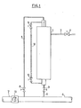
- the hydraulic circuit shown in FIG. 1 consists of a tank 1 connected by a pipe 2 to a filling valve 3, this tank being connected by its upper part and by its lower part to a manifold 4, respectively by a vent piping 5 and a piping of purge 6.
- a controller 7 On this manifold 4 is mounted a controller 7 according to the invention.
- the circuit comprises a column 10 serving as a reservoir level indicator 1 and comprising two taps 11 and 12.
- the circulation controller 7, which contains a movable leaf 13 and which will be described in detail with reference to FIGS. 2 and 3, is directly mounted on the manifold 4.
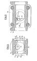
- the circulation controller 7 is shown in detail, fixed in a mounting flange shown diagrammatically and designated by the reference 14.
- the circulation controller 7 is formed by a cylindrical sleeve 15 whose cylindrical interior surface 16 intersects the cylindrical interior surface 17 of a cylinder 18 of the same internal diameter as that of the sleeve 15, the axis is perpendicular to the latter and which carries two circular flat end glasses 19 closing the assembly in leaktight manner and making it possible to observe the movable leaf 13.
- the latter can pivot around a horizontal axis 20, (perpendicular to the direction of movement of the fluid), the ends of which are mounted in lateral bearings 21 integral with the cylinder 18, so as to be able to assume a horizontal position.
- the leaf 13 has at its upper part a cutout or notch 22, for example of semi-circular shape. Furthermore the leaf 13 has vertical lateral edges 23 directly adjoining the vertical flat glasses 19 and a lower edge 24 whose profile is adjusted to the geometric surface located inside the circulation controller and relative to which the leaf 13 pivots. .
- the internal diameter of the manifold 4 on which the controller 7 is mounted is significantly greater than the diameter of the pipes which are connected to it.
- any retention zone is eliminated at the lower part of the sleeve 15 by the fact that at the intersection of the two internal cylindrical surfaces, 16 and 17, of the same diameter, all the lines of the surface 16 converge towards the lower generator of the surface 17.
- the filling of the reservoir 11 is carried out through line 2, the valve 9 is closed, it is ensured that the level 10 is in communication using the valves 11 and 12 and the vent valve 8 and the valve are opened.
- filling valve 3 The filling is finished when the water, overflowing from the tank 1 and discharged into the vent line 5, appears in the circulation controller 7 by moving the movable leaf 13 to the left.
- the tank is emptied by closing the filling valve 3 and opening the vent valve 8, then the drain valve 9 (the two level valves 11 - 12 remaining open). Under the effect of the pressure of the water column contained in the tank 1, the water flows through the tap 9 and is replaced in the tank by air which, after having traveled against the current in the controller 7 (through the clearance in the opening 22) enters said tank via the vent pipe 5.
- Fig. 4 shows the case of the purge manifold and the vents of several devices, such as for example a tank 26, a heat exchanger 27 and a pump 28 installed on circuits similar to that of FIG. 1 and connected in parallel on a common collecting pipe 29 with a diameter much greater than that of the various purge and vent lines 30, 31.
Landscapes
- Physics & Mathematics (AREA)
- General Physics & Mathematics (AREA)
- Monitoring And Testing Of Nuclear Reactors (AREA)
- Measuring Volume Flow (AREA)
- Indicating Or Recording The Presence, Absence, Or Direction Of Movement (AREA)
- Measurement Of Radiation (AREA)
- Pipeline Systems (AREA)
- Sliding Valves (AREA)
- Sampling And Sample Adjustment (AREA)
Priority Applications (1)
| Application Number | Priority Date | Filing Date | Title |
|---|---|---|---|
| AT82400324T ATE24773T1 (de) | 1981-03-02 | 1982-02-24 | Vorrichtung zur kontrolle der zirkulation eines fliessfaehigen mediums. |
Applications Claiming Priority (3)
| Application Number | Priority Date | Filing Date | Title |
|---|---|---|---|
| FR8104085 | 1981-03-02 | ||
| FR8104085A FR2500932A1 (fr) | 1981-03-02 | 1981-03-02 | Dispositif de controle de circulation de fluide |
| US06/355,084 US4484536A (en) | 1981-03-02 | 1982-03-05 | Apparatus for indicating fluid flow |
Publications (2)
| Publication Number | Publication Date |
|---|---|
| EP0059663A1 true EP0059663A1 (de) | 1982-09-08 |
| EP0059663B1 EP0059663B1 (de) | 1987-01-07 |
Family
ID=41557572
Family Applications (1)
| Application Number | Title | Priority Date | Filing Date |
|---|---|---|---|
| EP82400324A Expired EP0059663B1 (de) | 1981-03-02 | 1982-02-24 | Vorrichtung zur Kontrolle der Zirkulation eines fliessfähigen Mediums |
Country Status (6)
| Country | Link |
|---|---|
| US (1) | US4484536A (de) |
| EP (1) | EP0059663B1 (de) |
| JP (1) | JPS57158514A (de) |
| AT (1) | ATE24773T1 (de) |
| DE (1) | DE3275013D1 (de) |
| FR (1) | FR2500932A1 (de) |
Cited By (1)
| Publication number | Priority date | Publication date | Assignee | Title |
|---|---|---|---|---|
| EP0241791A1 (de) * | 1986-03-27 | 1987-10-21 | INTERMES S.p.A. | Durchflussmesser |
Families Citing this family (6)
| Publication number | Priority date | Publication date | Assignee | Title |
|---|---|---|---|---|
| JPS61140966U (de) * | 1985-02-21 | 1986-09-01 | ||
| US5343826A (en) * | 1991-08-19 | 1994-09-06 | Clark-Reliance Corporation | Fluid indicator assemblies for sight flow apparatus |
| WO2007016505A2 (en) * | 2005-08-01 | 2007-02-08 | Davis Chief R | Sewer line power generating system |
| US8800473B1 (en) * | 2010-08-06 | 2014-08-12 | Richard DeVerse | Mass velocity sensor device and method for remote monitoring and visual verification of fluid velocity |
| US9921094B2 (en) * | 2014-11-11 | 2018-03-20 | Intuitive Surgical Operations, Inc. | Flow indicators for surgical instrument reprocessing, and related systems and methods |
| US12326213B2 (en) * | 2021-04-16 | 2025-06-10 | Tmeic Corporation | Fluid check piping and electric power apparatus |
Citations (4)
| Publication number | Priority date | Publication date | Assignee | Title |
|---|---|---|---|---|
| US2687457A (en) * | 1951-03-14 | 1954-08-24 | Bamford And Company Ltd F | Fluid flow indicator |
| GB797238A (en) * | 1956-08-08 | 1958-06-25 | Yorkshire Tar Distillers Ltd | Sight glass, for observing liquid in a pipe |
| DE1763219A1 (de) * | 1968-04-22 | 1971-08-05 | Kyffhaeuserhuette Artern Veb M | Vorrichtung zur UEberwachung stroemender Medien in geschlossenen Rohrsystemen,vorzugsweise fuer Zentrifugalseparatoren |
| DE2200820A1 (de) * | 1972-01-08 | 1973-07-12 | Gerdts Gustav F Kg | Stroemungsanzeiger |
Family Cites Families (9)
| Publication number | Priority date | Publication date | Assignee | Title |
|---|---|---|---|---|
| US2029633A (en) * | 1934-09-24 | 1936-02-04 | Schutte & Koerting Company | Flow indicator |
| US2187257A (en) * | 1938-08-15 | 1940-01-16 | John C Williams Corp | Valve |
| US3251335A (en) * | 1964-09-15 | 1966-05-17 | William P Dannevik | Visual irrigation pipe flow indicator |
| US3610273A (en) * | 1969-03-13 | 1971-10-05 | Peters & Russel Inc | Compressor or like intake valve |
| US3565099A (en) * | 1970-01-02 | 1971-02-23 | John M Young | Reversible check valve |
| US3914994A (en) * | 1971-12-15 | 1975-10-28 | Philip M Banner | Liquid flow indicating and flow control means |
| US3745967A (en) * | 1971-12-23 | 1973-07-17 | Xomox Corp | Flow indicator |
| US3857277A (en) * | 1972-12-29 | 1974-12-31 | Laval Turbine | Flow indicator |
| US4274436A (en) * | 1979-08-16 | 1981-06-23 | Xomox Corporation | Wafer-type swing check valve construction |
-
1981
- 1981-03-02 FR FR8104085A patent/FR2500932A1/fr active Granted
-
1982
- 1982-02-24 DE DE8282400324T patent/DE3275013D1/de not_active Expired
- 1982-02-24 AT AT82400324T patent/ATE24773T1/de not_active IP Right Cessation
- 1982-02-24 EP EP82400324A patent/EP0059663B1/de not_active Expired
- 1982-03-01 JP JP3296082A patent/JPS57158514A/ja active Granted
- 1982-03-05 US US06/355,084 patent/US4484536A/en not_active Expired - Fee Related
Patent Citations (4)
| Publication number | Priority date | Publication date | Assignee | Title |
|---|---|---|---|---|
| US2687457A (en) * | 1951-03-14 | 1954-08-24 | Bamford And Company Ltd F | Fluid flow indicator |
| GB797238A (en) * | 1956-08-08 | 1958-06-25 | Yorkshire Tar Distillers Ltd | Sight glass, for observing liquid in a pipe |
| DE1763219A1 (de) * | 1968-04-22 | 1971-08-05 | Kyffhaeuserhuette Artern Veb M | Vorrichtung zur UEberwachung stroemender Medien in geschlossenen Rohrsystemen,vorzugsweise fuer Zentrifugalseparatoren |
| DE2200820A1 (de) * | 1972-01-08 | 1973-07-12 | Gerdts Gustav F Kg | Stroemungsanzeiger |
Cited By (1)
| Publication number | Priority date | Publication date | Assignee | Title |
|---|---|---|---|---|
| EP0241791A1 (de) * | 1986-03-27 | 1987-10-21 | INTERMES S.p.A. | Durchflussmesser |
Also Published As
| Publication number | Publication date |
|---|---|
| JPS6161606B2 (de) | 1986-12-26 |
| FR2500932A1 (fr) | 1982-09-03 |
| US4484536A (en) | 1984-11-27 |
| FR2500932B1 (de) | 1984-04-20 |
| DE3275013D1 (en) | 1987-02-12 |
| EP0059663B1 (de) | 1987-01-07 |
| ATE24773T1 (de) | 1987-01-15 |
| JPS57158514A (en) | 1982-09-30 |
Similar Documents
| Publication | Publication Date | Title |
|---|---|---|
| EP0084754B1 (de) | Rückflussverhinderer für Druckleitungen | |
| EP0059663B1 (de) | Vorrichtung zur Kontrolle der Zirkulation eines fliessfähigen Mediums | |
| EP1445024A1 (de) | Anlage zum Magnetfiltern von Schlämmen | |
| FR2672100A1 (fr) | Vanne de coupure automatique a deux etages. | |
| EP0617788B1 (de) | Vorrichtung zur entnahme von flüssigkeitsproben aus einem tank oder aus einem chemischen reaktor | |
| EP0494818B1 (de) | Fernbedienbare Fülleinrichtung eines Ölbehälters | |
| EP0121456B1 (de) | Tauchpumpe mit Laufrad | |
| BE1016948A6 (fr) | Siphon de cour (sterfput). | |
| WO1988003246A1 (fr) | Installation d'enfutage | |
| FR2670270A1 (fr) | Poste de purge monobloc a robinets d'isolement incorpores. | |
| EP1738097B1 (de) | Verteilervorrichtung zur verteilung einer gasströmung mit einer einzelnen klappe | |
| FR2621083A1 (fr) | Pompe immergee de prelevement de liquide dans une conduite, notamment une conduite de rejet en eau profonde d'eaux de refroidissement de centrale nucleaire | |
| EP3924080A1 (de) | Einschlussvorrichtung für einen rotationsverdampfer | |
| FR2486240A1 (fr) | Vanne pour prise d'echantillons | |
| EP2804685A1 (de) | Vorrichtung zum sammeln von klarwasser | |
| EP4656810A1 (de) | Sanitäre wasserauslaufarmatur und sanitäre spüleinrichtung mit einer solchen ablaufarmatur | |
| FR3162790A1 (fr) | Système mécanique muni d’un dispositif de prélèvement d’huile | |
| FR2844731A1 (fr) | Boitier de lavage pour nez de vidange d'un tank refroidisseur de lait | |
| FR2660375A1 (fr) | Pompe de circulation d'un liquide caloporteur en circuit ferme. | |
| EP1310716B1 (de) | Entlüftungsvorrichtung | |
| FR3021060A1 (fr) | Systeme de remplissage de reservoir de chasse d'eau | |
| BE846103A (fr) | Purgeur automatique de gaz | |
| FR2816025A1 (fr) | Clapet d'entree d'air | |
| FR3016643A1 (fr) | Perfectionnement pour regard de visite destine a la surveillance de reseaux souterrains | |
| FR2878541A1 (fr) | Puits d'egout muni d'un dispositif de regulation et/ou de mesure de debit |
Legal Events
| Date | Code | Title | Description |
|---|---|---|---|
| PUAI | Public reference made under article 153(3) epc to a published international application that has entered the european phase |
Free format text: ORIGINAL CODE: 0009012 |
|
| AK | Designated contracting states |
Designated state(s): AT BE CH DE GB IT LU NL SE |
|
| 17P | Request for examination filed |
Effective date: 19821015 |
|
| RAP1 | Party data changed (applicant data changed or rights of an application transferred) |
Owner name: ETABLISSEMENTS TROUVAY & CAUVIN SOCIETE ANONYME |
|
| GRAA | (expected) grant |
Free format text: ORIGINAL CODE: 0009210 |
|
| ITF | It: translation for a ep patent filed | ||
| RAP1 | Party data changed (applicant data changed or rights of an application transferred) |
Owner name: ETABLISSEMENTS TROUVAY & CAUVIN SOCIETE ANONYME |
|
| AK | Designated contracting states |
Kind code of ref document: B1 Designated state(s): AT BE CH DE GB IT LI LU NL SE |
|
| REF | Corresponds to: |
Ref document number: 24773 Country of ref document: AT Date of ref document: 19870115 Kind code of ref document: T |
|
| REF | Corresponds to: |
Ref document number: 3275013 Country of ref document: DE Date of ref document: 19870212 |
|
| PGFP | Annual fee paid to national office [announced via postgrant information from national office to epo] |
Ref country code: AT Payment date: 19870213 Year of fee payment: 6 |
|
| PG25 | Lapsed in a contracting state [announced via postgrant information from national office to epo] |
Ref country code: LU Free format text: LAPSE BECAUSE OF NON-PAYMENT OF DUE FEES Effective date: 19870228 |
|
| PGFP | Annual fee paid to national office [announced via postgrant information from national office to epo] |
Ref country code: NL Payment date: 19870228 Year of fee payment: 6 |
|
| PLBE | No opposition filed within time limit |
Free format text: ORIGINAL CODE: 0009261 |
|
| STAA | Information on the status of an ep patent application or granted ep patent |
Free format text: STATUS: NO OPPOSITION FILED WITHIN TIME LIMIT |
|
| 26N | No opposition filed | ||
| PG25 | Lapsed in a contracting state [announced via postgrant information from national office to epo] |
Ref country code: GB Effective date: 19890224 Ref country code: AT Effective date: 19890224 |
|
| PG25 | Lapsed in a contracting state [announced via postgrant information from national office to epo] |
Ref country code: SE Effective date: 19890225 |
|
| PG25 | Lapsed in a contracting state [announced via postgrant information from national office to epo] |
Ref country code: LI Effective date: 19890228 Ref country code: CH Effective date: 19890228 Ref country code: BE Effective date: 19890228 |
|
| BERE | Be: lapsed |
Owner name: ETS TROUVAY & CAUVIN S.A. Effective date: 19890228 |
|
| PG25 | Lapsed in a contracting state [announced via postgrant information from national office to epo] |
Ref country code: NL Effective date: 19890901 |
|
| NLV4 | Nl: lapsed or anulled due to non-payment of the annual fee | ||
| GBPC | Gb: european patent ceased through non-payment of renewal fee | ||
| REG | Reference to a national code |
Ref country code: CH Ref legal event code: PL |
|
| PG25 | Lapsed in a contracting state [announced via postgrant information from national office to epo] |
Ref country code: DE Effective date: 19891101 |
|
| EUG | Se: european patent has lapsed |
Ref document number: 82400324.8 Effective date: 19900118 |