EP0059889A1 - Méthode de surveillance de courants de conducteur et installation pour la mise en oeuvre de la méthode - Google Patents
Méthode de surveillance de courants de conducteur et installation pour la mise en oeuvre de la méthode Download PDFInfo
- Publication number
- EP0059889A1 EP0059889A1 EP19820101444 EP82101444A EP0059889A1 EP 0059889 A1 EP0059889 A1 EP 0059889A1 EP 19820101444 EP19820101444 EP 19820101444 EP 82101444 A EP82101444 A EP 82101444A EP 0059889 A1 EP0059889 A1 EP 0059889A1
- Authority
- EP
- European Patent Office
- Prior art keywords
- field strength
- pulses
- magnetization
- winding
- magnetic core
- Prior art date
- Legal status (The legal status is an assumption and is not a legal conclusion. Google has not performed a legal analysis and makes no representation as to the accuracy of the status listed.)
- Granted
Links
- 238000000034 method Methods 0.000 title claims abstract description 10
- 239000004020 conductor Substances 0.000 title claims abstract description 9
- 238000004804 winding Methods 0.000 claims abstract description 27
- 238000012544 monitoring process Methods 0.000 claims abstract description 12
- 230000005415 magnetization Effects 0.000 claims abstract description 9
- 239000011162 core material Substances 0.000 description 21
- 238000010586 diagram Methods 0.000 description 7
- 230000000694 effects Effects 0.000 description 3
- 238000001208 nuclear magnetic resonance pulse sequence Methods 0.000 description 3
- 229910045601 alloy Inorganic materials 0.000 description 2
- 239000000956 alloy Substances 0.000 description 2
- 230000000737 periodic effect Effects 0.000 description 2
- 230000005417 remagnetization Effects 0.000 description 2
- 229910000859 α-Fe Inorganic materials 0.000 description 2
- 230000006698 induction Effects 0.000 description 1
- 238000009413 insulation Methods 0.000 description 1
- 239000000696 magnetic material Substances 0.000 description 1
- 230000003287 optical effect Effects 0.000 description 1
- 230000001681 protective effect Effects 0.000 description 1
- 239000000523 sample Substances 0.000 description 1
Images

Classifications
-
- H—ELECTRICITY
- H02—GENERATION; CONVERSION OR DISTRIBUTION OF ELECTRIC POWER
- H02H—EMERGENCY PROTECTIVE CIRCUIT ARRANGEMENTS
- H02H3/00—Emergency protective circuit arrangements for automatic disconnection directly responsive to an undesired change from normal electric working condition with or without subsequent reconnection ; integrated protection
- H02H3/26—Emergency protective circuit arrangements for automatic disconnection directly responsive to an undesired change from normal electric working condition with or without subsequent reconnection ; integrated protection responsive to difference between voltages or between currents; responsive to phase angle between voltages or between currents
- H02H3/32—Emergency protective circuit arrangements for automatic disconnection directly responsive to an undesired change from normal electric working condition with or without subsequent reconnection ; integrated protection responsive to difference between voltages or between currents; responsive to phase angle between voltages or between currents involving comparison of the voltage or current values at corresponding points in different conductors of a single system, e.g. of currents in go and return conductors
- H02H3/33—Emergency protective circuit arrangements for automatic disconnection directly responsive to an undesired change from normal electric working condition with or without subsequent reconnection ; integrated protection responsive to difference between voltages or between currents; responsive to phase angle between voltages or between currents involving comparison of the voltage or current values at corresponding points in different conductors of a single system, e.g. of currents in go and return conductors using summation current transformers
- H02H3/332—Emergency protective circuit arrangements for automatic disconnection directly responsive to an undesired change from normal electric working condition with or without subsequent reconnection ; integrated protection responsive to difference between voltages or between currents; responsive to phase angle between voltages or between currents involving comparison of the voltage or current values at corresponding points in different conductors of a single system, e.g. of currents in go and return conductors using summation current transformers with means responsive to DC component in the fault current
Definitions
- the invention relates to a method for monitoring conductor currents for a fault current that changes the bias of a magnetic circuit.
- magnetic circuits which contain a ring core made of a highly permeable alloy with a flat magnetic characteristic. Such cores are relatively expensive.
- the invention is therefore based on the object of specifying a method for monitoring conductor currents in which the magnetic circuit can contain an inexpensive ferrite core.
- a predetermined field strength is generated in the magnetic circuit with an at least approximately rectangular magnetization loop and a predetermined coercive field strength by superimposing a test pulse and a magnetic reversal pulse with a predetermined current strength, and that the field strength generated by the sum of this field strength and a differential current induced voltage is measured and a monitoring signal is derived if this voltage exceeds a predetermined limit value within a mask pulse.
- the magnetic core is provided with a write winding and a read winding.
- a clock generator supplies write signals for the write winding and a coincidence circuit, which establishes a logical combination of the write and read signals.
- the magnetic circuit can contain both a ring core and a ferrite core.
- the core material with a rectangular characteristic is selected so that the coercive field strength determines the measuring range for the fault current.
- the coercive field strength can preferably be selected to be approximately twice as large as the field strength generated by a still permissible nominal residual current.
- the clock generator outputs pulses with a predetermined field strength profile to the write winding.
- the write pulse exceeds the coercive field strength and the magnetic core is remagnetized. This process induces a significantly higher voltage in the reading winding than in the case of no premagnetization.
- the level of the output pulse at the reading winding is thus used as a criterion for the presence of an impermissibly high fault current.
- the toroid is magnetized completely by pulses with sufficient field strength.
- the output signal of the reading winding is digitized by comparators. This gives a digital function of the entire arrangement and a correspondingly simple hardware structure that can be easily integrated. Such digital electronics do not require closely tolerated components and also do not require any adjustment work.
- the response times of the monitoring arrangement can be limited to approximately 1 to 2 ms.
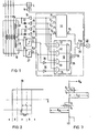
- FIG. 1 schematically illustrates an exemplary embodiment of an arrangement for carrying out the method according to the invention as a circuit diagram.
- Figure 2 shows the magnetisie tion characteristic of the magnetic core and in Figures 3 to 6, the write pulses are each illustrated in a diagram.
- FIG. 7 shows the effect of the write pulses in the magnetic core and in FIGS. 8 to 10 the voltage pulses on the read winding and the digital signals derived therefrom are shown schematically in various diagrams.
- FIG. 11 shows digital output pulses from the clock generator, which serve as a mask.
- the three-phase supply line of a system contains a circuit breaker 2, the switch lock 4 of which is provided with a release 6.
- the three-phase conductors R, S and T and the center conductor Mp are passed through the magnetic core 12 of a magnetic circuit 10 which is provided with two secondary windings, one of which serves as a write winding 8 and the other as a read winding 9 and which is magnetically coupled via the core 12 are.
- a clock generator 20 is provided in the write circuit 14, which supplies digital pulses P 1 to P 4 on separate and unspecified output lines and takes over the sequence control.
- the pulses P 1 and P 3 serve as test pulses and are applied to the write winding 8 via amplifiers, so-called drivers 15 and 17, respectively.
- the pulses P 2 and P 4 serve as magnetic reversal pulses and are likewise fed to the write winding 8 in the opposite direction via drivers 16 and 18, respectively.
- the output lines of drivers 16 and 18 each contain a decoupling diode 22 and 23, respectively.
- the pulses induced in the reading winding 9 are digitized in the reading circuit 24 via electronic comparators 26 and 27 and their output signals U 26 and U 27 are fed to a coincidence circuit 30, which represents an AND-OR gate and contains four AND gates 31 to 34, which is followed by an OR gate 35. Additional inverters 28 and 29 are arranged in the output lines of the comparators 26 and 27.
- the output signal U 35 of the coincidence circuit 30 is fed to an input of a further AND gate 38, the second input of which is a sequence of pulses P 5 of the clock generator 20, which serve as a mask.
- a monitoring signal U 38 thus appears when the mask pulses P 5 coincide with an output signal U 35 of the coincidence circuit 30.
- the monitoring signal U 38 has a warning function and can cause an acoustic or optical display, which is indicated in the figure by a lamp 40, which can be a luminescent diode, for example.
- the monitoring signal U 38 can also be used to switch off the system (not shown) and, for this purpose, be fed to the trigger 6, which actuates the switch 2 via the lock 4.
- the soft magnetic material of the magnetic core 12 has an approximately rectangular magnetization characteristic curve, the induction B of which changes abruptly at a predetermined coercive field strength H c .
- the field strength H which are generated in the magnetic core 12 both by a differential current FI and by the write pulses P 1 to P 4 , different display areas a to e are assumed.
- a field strength H ⁇ N should be induced by the nominal fault current FI.
- the differential current FI remains smaller than the permissible fault current I ⁇ N . It is therefore only necessary to select the field strength H induced in the magnetic circuit 12 by the write pulse, for example the test pulse P 1 .
- the usually made of H-level signals (high) or L-level signals (low) output signals U 26 and U 27 of the comparators 26 and 27 in the reading circuit 24 does not now, for example, change Samuel.Wird the amplitude of the Ummagnetleiterspulse P 2 and P 4 corresponding to a field strength selected, the fault current FI triggers the following digital signals U 26 and U 27 in comparison to the permissible fault current I ⁇ N according to the following table in the display areas b to e:
- An impermissibly high fault current FI is recognized by the logical equation while at least one of the mask pulses P 5 is fulfilled.
- the clock generator 20 of the sequence control delivers its test pulse P 1 at time t 0 .
- the magnetization pulse P 2 follows in accordance with the diagram in FIG. 4, which adds up to the pulse P 1 and thus generates a field strength H u2 in the core 12 which is sufficient for magnetization.
- a test pulse P 3 follows after the diagram in FIG. 5, and at time t 9 according to the diagram in FIG. 6, another magnetic reversal pulse P 4 , which generates a field strength H u4 sufficient for magnetic reversal, as indicated in FIG.
- the respectively obtained positive or negative write field strength H w on the write winding 8 is illustrated schematically as a function of the time t.
- the field strength H P1 generated by the test pulse P 1 is not greater than the residual current field strength H ⁇ N .
- the H u2 of the remagnetization pulse P 2 clearly exceeds the coercive field strength H c and the core 12 is remagnetized.
- a read signal U 9 is obtained which has a limit value U s which can be set on the comparator 26 steps and a digital read pulse U 26 with steep edges is formed according to FIG. 9, which can be fed to the coincidence circuit 30.
- the comparator 26 can contain an electronic toggle amplifier, for example a Schmitt trigger.
- the digital read pulse U 27 is formed in the same way from the analog read signal U 9 by the write pulses P 3 and P 4 according to FIGS. 8 and 10.
- the read pulses U 26 and U 27 are linked in the coincidence circuit 30 with the write pulses P1 to P 4 and the output pulses of this coincidence circuit 30 are supplied to the AND gate 38 together with the pulses P 5 according to FIG. 11 as a mask.
- An output signal U 381 thus appears whenever the logic equation is satisfied during one of the mask pulses P 5 .
- the output signals U 38 can now either be used exclusively for monitoring and, for example, only be supplied to the lamp 40 or at the same time serve to switch off a system and be supplied to the trigger 6 of the switch 2 for this purpose.
- the effect of the output signal can be adapted to the size of the differential current FI.
- triggering of the switch 2 can only be provided if a fault current FI is present in the measuring ranges c and e, while the display 40 responds for differential currents in the ranges b and d.
Landscapes
- Engineering & Computer Science (AREA)
- Power Engineering (AREA)
- Measuring Instrument Details And Bridges, And Automatic Balancing Devices (AREA)
- Measuring Magnetic Variables (AREA)
- Emergency Protection Circuit Devices (AREA)
Applications Claiming Priority (2)
| Application Number | Priority Date | Filing Date | Title |
|---|---|---|---|
| DE19813108906 DE3108906A1 (de) | 1981-03-09 | 1981-03-09 | "verfahren zur ueberwachung von leiterstroemen und anordnung zur durchfuehrung des verfahrens" |
| DE3108906 | 1981-03-09 |
Publications (2)
| Publication Number | Publication Date |
|---|---|
| EP0059889A1 true EP0059889A1 (fr) | 1982-09-15 |
| EP0059889B1 EP0059889B1 (fr) | 1985-11-13 |
Family
ID=6126727
Family Applications (1)
| Application Number | Title | Priority Date | Filing Date |
|---|---|---|---|
| EP19820101444 Expired EP0059889B1 (fr) | 1981-03-09 | 1982-02-25 | Méthode de surveillance de courants de conducteur et installation pour la mise en oeuvre de la méthode |
Country Status (3)
| Country | Link |
|---|---|
| EP (1) | EP0059889B1 (fr) |
| JP (1) | JPS57160323A (fr) |
| DE (1) | DE3108906A1 (fr) |
Cited By (1)
| Publication number | Priority date | Publication date | Assignee | Title |
|---|---|---|---|---|
| US4819125A (en) * | 1987-07-23 | 1989-04-04 | Mitsubishi Denki Kabushiki Kaisha | Overcurrent detector |
Families Citing this family (3)
| Publication number | Priority date | Publication date | Assignee | Title |
|---|---|---|---|---|
| DE8909649U1 (de) * | 1989-08-11 | 1990-12-06 | Siemens AG, 1000 Berlin und 8000 München | Signalumsetzer mit freibleibendem Eingangsspannungspegel |
| DE19506860C1 (de) * | 1995-02-15 | 1996-08-08 | Siemens Ag | Verfahren zur Erfassung eines Erdschlußstromes |
| DE19602911A1 (de) * | 1996-01-27 | 1997-07-31 | Abb Patent Gmbh | Schaltungsanordnung zur Detektion eines Fehlerstromes |
Citations (4)
| Publication number | Priority date | Publication date | Assignee | Title |
|---|---|---|---|---|
| US3614533A (en) * | 1970-05-20 | 1971-10-19 | Rucker Co | Ground fault detector and circuit interrupter by magnetic flux storage method |
| DE2555255A1 (de) * | 1975-12-09 | 1977-06-16 | Bbc Brown Boveri & Cie | Einrichtung zur erfassung von fehlerstroemen |
| DE2550060B2 (de) * | 1975-10-13 | 1978-03-02 | Bbc Ag Brown, Boveri & Cie, Baden, Aargau (Schweiz) | Verfahren und Einrichtung zur Detektion eines Magnetfeldes |
| EP0014938A1 (fr) * | 1979-02-23 | 1980-09-03 | Siemens Aktiengesellschaft | Procédé pour la surveillance courants de conducteurs à l'égard d'un courant de défaut et dispositif pour la mise en oeuvre de ce procédé |
Family Cites Families (1)
| Publication number | Priority date | Publication date | Assignee | Title |
|---|---|---|---|---|
| DE2851050A1 (de) * | 1978-11-25 | 1980-06-04 | Messerschmitt Boelkow Blohm | Schaltungsanordnung zum vergleichen von analogsignalen |
-
1981
- 1981-03-09 DE DE19813108906 patent/DE3108906A1/de not_active Withdrawn
-
1982
- 1982-02-25 EP EP19820101444 patent/EP0059889B1/fr not_active Expired
- 1982-03-08 JP JP3631882A patent/JPS57160323A/ja active Pending
Patent Citations (5)
| Publication number | Priority date | Publication date | Assignee | Title |
|---|---|---|---|---|
| US3614533A (en) * | 1970-05-20 | 1971-10-19 | Rucker Co | Ground fault detector and circuit interrupter by magnetic flux storage method |
| DE2550060B2 (de) * | 1975-10-13 | 1978-03-02 | Bbc Ag Brown, Boveri & Cie, Baden, Aargau (Schweiz) | Verfahren und Einrichtung zur Detektion eines Magnetfeldes |
| DE2555255A1 (de) * | 1975-12-09 | 1977-06-16 | Bbc Brown Boveri & Cie | Einrichtung zur erfassung von fehlerstroemen |
| EP0014938A1 (fr) * | 1979-02-23 | 1980-09-03 | Siemens Aktiengesellschaft | Procédé pour la surveillance courants de conducteurs à l'égard d'un courant de défaut et dispositif pour la mise en oeuvre de ce procédé |
| DE2907171A1 (de) * | 1979-02-23 | 1980-09-04 | Siemens Ag | Verfahren zur ueberwachung von leiterstroemen auf einen fehlerstrom und anordnung zur durchfuehrung des verfahrens |
Cited By (1)
| Publication number | Priority date | Publication date | Assignee | Title |
|---|---|---|---|---|
| US4819125A (en) * | 1987-07-23 | 1989-04-04 | Mitsubishi Denki Kabushiki Kaisha | Overcurrent detector |
Also Published As
| Publication number | Publication date |
|---|---|
| EP0059889B1 (fr) | 1985-11-13 |
| DE3108906A1 (de) | 1982-09-16 |
| JPS57160323A (en) | 1982-10-02 |
Similar Documents
| Publication | Publication Date | Title |
|---|---|---|
| EP0179384B1 (fr) | Commutateur de proximité insensible aux champs parasites | |
| DE3008527C2 (de) | Schaltungsanordnung zur digitalen Fernübertragung von Signalen | |
| DE2203154A1 (de) | Detektor fuer die Spitzen eines Analogsignals mit zeitlich veraenderlicher Amplitude | |
| DE2221048C2 (de) | Anordnung zur Feststellung von Zeitintervallen, in denen das Meßsignal eines Meßtransformators aufgrund seines Sättigungszustandes fehlerhaft ist | |
| DE69116397T2 (de) | Gleichstrommonitor | |
| DE3723568C2 (de) | Differenzstromschutzschalter | |
| EP0059889B1 (fr) | Méthode de surveillance de courants de conducteur et installation pour la mise en oeuvre de la méthode | |
| DE3543985A1 (de) | Anordnung zum erfassen von fehlerstroemen | |
| EP0014938B1 (fr) | Procédé pour la surveillance courants de conducteurs à l'égard d'un courant de défaut et dispositif pour la mise en oeuvre de ce procédé | |
| DE3543948C2 (fr) | ||
| DE4135425C2 (de) | Vorrichtung zum Feststellen und Anzeigen eines Fehlers in elektrischen Leitungen | |
| DE1424494A1 (de) | Magnetwandlersystem | |
| DE3824267C2 (fr) | ||
| EP0046317A1 (fr) | Procédé et dispositif pour détecter la direction d'un court-circuit | |
| DE2014089A1 (de) | Schaltung zur Erzeugung eines dem Nulldurchgang eines Wechselstromes um eine konstante Zeit voreilenden Ausgangssignals | |
| EP0005694A2 (fr) | Disjoncteur de protection contre des courants de défaut | |
| DE3445031A1 (de) | Kurzschlusssichere transistor-endstufe | |
| DE4011231C2 (fr) | ||
| AT385603B (de) | Schaltung zur erfassung der polaritaet eines von wechselstroemen ueberlagerten gleichstromes | |
| DE1449627C3 (de) | Kontrolleinrichtung für Ausgabevorrichtungen datenverarbeitender Maschinen | |
| DE2242634C3 (de) | Schaltungsanordnung zur schnellen Stromnullmeldung | |
| DE2226639C3 (de) | Nicht-lineare Vorrichtung zum Erfassen eines magnetischen Flusses | |
| AT253561B (de) | Schaltung zum Auslösen eines kurzen Einzelimpulses an Anfang und/oder Ende einer Impulsfolge | |
| DE2533483C3 (de) | Einrichtung zur Abfrage von durch Stellungen von Meldeschaltern in digitalen Geräten dargestellten Informationen | |
| DE3639623A1 (de) | Vorrichtung zur direkten digitalen messung von elektrischen stroemen und magnetischen feldern |
Legal Events
| Date | Code | Title | Description |
|---|---|---|---|
| PUAI | Public reference made under article 153(3) epc to a published international application that has entered the european phase |
Free format text: ORIGINAL CODE: 0009012 |
|
| AK | Designated contracting states |
Designated state(s): BE FR IT NL |
|
| 17P | Request for examination filed |
Effective date: 19830207 |
|
| GRAA | (expected) grant |
Free format text: ORIGINAL CODE: 0009210 |
|
| ITF | It: translation for a ep patent filed | ||
| AK | Designated contracting states |
Designated state(s): BE FR IT NL |
|
| ET | Fr: translation filed | ||
| PLBE | No opposition filed within time limit |
Free format text: ORIGINAL CODE: 0009261 |
|
| STAA | Information on the status of an ep patent application or granted ep patent |
Free format text: STATUS: NO OPPOSITION FILED WITHIN TIME LIMIT |
|
| 26N | No opposition filed | ||
| PGFP | Annual fee paid to national office [announced via postgrant information from national office to epo] |
Ref country code: NL Payment date: 19870228 Year of fee payment: 6 |
|
| PG25 | Lapsed in a contracting state [announced via postgrant information from national office to epo] |
Ref country code: BE Effective date: 19890228 |
|
| BERE | Be: lapsed |
Owner name: SIEMENS A.G. BERLIN UND MUNCHEN Effective date: 19890228 |
|
| PG25 | Lapsed in a contracting state [announced via postgrant information from national office to epo] |
Ref country code: NL Effective date: 19890901 |
|
| NLV4 | Nl: lapsed or anulled due to non-payment of the annual fee | ||
| PG25 | Lapsed in a contracting state [announced via postgrant information from national office to epo] |
Ref country code: FR Free format text: LAPSE BECAUSE OF NON-PAYMENT OF DUE FEES Effective date: 19891027 |
|
| REG | Reference to a national code |
Ref country code: FR Ref legal event code: ST |