EP0059893A2 - Gerät zum Steuern des Auf- und Abwickelns von Handtuchstoffrollen oder dgl. - Google Patents
Gerät zum Steuern des Auf- und Abwickelns von Handtuchstoffrollen oder dgl. Download PDFInfo
- Publication number
- EP0059893A2 EP0059893A2 EP82101456A EP82101456A EP0059893A2 EP 0059893 A2 EP0059893 A2 EP 0059893A2 EP 82101456 A EP82101456 A EP 82101456A EP 82101456 A EP82101456 A EP 82101456A EP 0059893 A2 EP0059893 A2 EP 0059893A2
- Authority
- EP
- European Patent Office
- Prior art keywords
- toweling
- roll
- loop
- roller
- spring
- Prior art date
- Legal status (The legal status is an assumption and is not a legal conclusion. Google has not performed a legal analysis and makes no representation as to the accuracy of the status listed.)
- Withdrawn
Links
Images


Classifications
-
- A—HUMAN NECESSITIES
- A47—FURNITURE; DOMESTIC ARTICLES OR APPLIANCES; COFFEE MILLS; SPICE MILLS; SUCTION CLEANERS IN GENERAL
- A47K—SANITARY EQUIPMENT; ACCESSORIES THEREFOR, e.g. TOILET ACCESSORIES
- A47K10/00—Body-drying implements; Toilet paper; Holders therefor
- A47K10/24—Towel dispensers; Toilet paper dispensers
- A47K10/28—Towel dispensers; Toilet paper dispensers dispensing a clean part and taking-up a soiled part, e.g. using rolls; with dispensers for soap or other detergents; with disinfecting or heating devices
Definitions
- the invention relates to an apparatus for controlling the winding up and the unwinding of toweling or the like.
- the toweling used in public places is generally made of well-known textile fabrics wound on rolls, and held by suitable support members which control the unwinding and the winding up of the toweling. These operations are performed by a user who pulls or draws a length of projecting toweling to form a loop beneath the apparatus. The loop of toweling used from time to time is replaced by a new length of toweling which is again unrolled and wound up on the relative rolls, and so forth.
- the invention aims at eliminating these disadvantages by withdrawing to the interior of the cabinet of the apparatus the end run of the roll at the termination of the unwinding of the roll.
- Another object of the invention is to provide an apparatus adapted to control the unwinding and the winding up of tow el ing, in a simple and practical way, ensuring that the placing and the replacing of new rolls and of the soiled ones are promptly handled even by persons of limited mechanical skill and without the use of tools of any kind.
- Still another object of the invention is to provide an apparatus of the described type which, in addition to ready replacement of new and soiled rolls, attains the goal of varying and controlling with equal ease and readiness the length of the loop extending from the cabinet of the apparatus.
- still another object of the invention is to provide an apparatus which, together with the aforementioned objects, eliminates the possibility of unauthorized tampering.
- the apparatus of the invention encompasses two rolls or rollers of towleing, respectively for unwinding and winding up, and so located that a length of toweling between said rolls forms outside the apparatus a loop of predetermined length, which is successively advanced, time after time, the initial run of the.loop being controlled by sensing means responsive to the user's pull.
- the apparatus also comprises an energy accumulator connected via unidirectional engaging means to wind-up means, there being provided means for winding said accumulator in operative communication with control means, actuated by the unwinding of a run of the loop; there are provided locking members for said accumulator, controlled by sensing means and in communication with the initial portion of the loop for revealing its presence in such manner that, when said sensing means signal the absence of the initial length of the loop, there are released the locking members of the energy accumulator, thereby actuating via unidirectional clutch means said wind-up means to retract to the interior of the apparatus the terminal length of the loop projecting from said apparatus.
- the energy accumulator connected to the wind-up means incorporates springs, preferably a coil spring.
- springs preferably a coil spring.
- One end of a spring is attached to a box accommodating said spring and the other end, via a speed reducer, to wind-up means of the toweling, a clutch means of unidirectional friction being disposed between said toweling wind-up means and a speed reducer, to limit the load on the springs and to rotate in the proper direction said toweling wind-up means at the end of the unwinding of the roll.
- the invention will now be described with reference to the accompanying drawings which, by way of example, illustrate a preferred embodiment of the apparatus which controls the unwinding and the winding up of toweling whose ends are in the form of rolls.
- the illustrated apparatus also comprises means for controlling the intermittent unwinding of the toweling and other means for automatically retracting a length of the end of the toweling from the exhausted roll. More particularly:
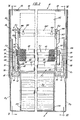
- the illustrated apparatus embodies a cabinet A of substantially elliptical transverse cross section and comprised of three stationarily joined members which form three chambers to stationarily and in juxtaposed positions accommodate two toweling rolls B 1 and B 2 ; and intermediate suitable length of toweling projects beneath said cabinet A.
- cabinet A comprises a base plate A 1 mounted and suitably anchored to wall C, for example, by screws C 1 .
- the upper edge 10 of the base plate A 1 supports by means of hinges 12 a cover A 2 , whose upper part is arcuate and which, jointly with said base plate, defines a semicircular chamber to receive the roll of soiled toweling B 1 , which, on being unwound from roll B 2 , is rewound in a manner hereinafter described.
- the base plate A 1 supports a second cover A3 constituting a pivotable receptacle having a semicylindrical bottom to rotatably accommodate toweling roll B 2 such that the initial run B 4 is unreeled outside the cabinet A in a manner which will presently be described.
- the pivotable receptacle A3 comprises, in correspondence with its rear wall, a cross-piece 14 (see Figs. 4 and 7) whose ends constitute slide journals which cooperate with guide bars 16 provided beneath the base plate A 1 .
- the ends of the slide cross-piece 14 also provide two pivots for movably holding the pivotable receptacle A3 so that, in addition to swinging around said pivots, it can be horizontally shifted along the bars 16 until it reaches position 14' arrested by catches 15 of Figure 7 to make possible the introduction into such cover of the roll B 2 of the toweling to be unwound.
- Cover A 2 and receptacle A3 are held in engagement either with base plate A 1 or with each other by conveniently disposed latches. More specifically, and as illustrated in Figure 7, the front wall of cover A 2 downwardly presents brackets 18, which hold corresponding zip-like hooks 20 in angular joint relation on a polygonal plate 22 whose ends are conveniently supported for simultaneous rotation. Hooks 20 are rotated in the clockwise direction (Fig. 7) by the action of the corresponding flexible blades 23, whose free ends slidingly engage a projection interiorly presented from cover A 2 . In the action of the flexible blades 23, together with said cover participate catch nibs 24 associated with the corresponding hooks 20.
- Every hook 20 ends at its free end with an aperture 26, in which is engaged a tooth 28 supported at the front end of each. of guide bars 16 integral with the base plate A l .
- the front wall of the pivotable receptacle A3 is provided near its edge with two windows 30, in which are engaged flexible teeth 32 provided at the ends of the guide bars 16 for holding said receptacle locked in a closed condition.
- the front wall of cover A 2 substantially projects relative to the corresponding wall of the pivotable receptacle A3 and the lower edge 34 is arcuate and extends to conceal the windows 30.
- said arcuate edge 34 is provided, in correspondence with the windows 30, with tongues 33 which engage the lower portions of said windows thus to lock the flexible teeth 32 in the closed position.
- the end of the arcuate edge 34 is disposed to be at a convenient distance from an edge 35 provided in the upper portion of receptacle A3 to form a slot through which passes and exits from the cover a run of the toweling B 5 , as will be later described.
- the two tongues 33 are wedge- shaped and by flexible force are engaged between the lower areas of windows 30 and are at the upper part limited by flexible teeth 32.
- a locking chain for the movable parts A 2 and A3 of the cabinet A facing hooks 20 which in the illustrated case are actuated by a lock D comprising one of the side walls of the cover A 2 ( Figure 1).
- the base plate A l in addition to the movable parts A 2 and A 3' also supports a support frame E for a first complementary device F, which controls the unwinding of toweling B from roll B 2 and the winding-up of the soiled toweling on roll B 1 .
- the support frame E comprises two vertical plates E 1 and E 2' which are stationarily joined to said base body by stationary connecting means, provided by pairs of small plates E 3 having slots and cooperating surface to surface with said vertical plates.
- the small plates E 3 are perforated for holding either screws E 4 which lock the support frame E or for holding in spaced vertical relationship vertical plates E 1 and E 2 such that toweling B can unobstructedly run therebetween as will be described presently.
- plate E 1 comprises also a device F 2 for determining and controlling the length of toweling B 6 extending outside of the apparatus in order to form a loop of predetermined length.
- the other plate E 2 accordingly holds another device F 3 which at the end of the unwinding of the roll B 2 (and, consequently, the winding-up of roll B 1 ) automatically intervenes for retracting to the interior of cabinet A the final portion of the toweling from roll B 2 to be wound up on roll B 1 .
- roll B 1 of the unwound toweling is rotatably disposed within the pivotable receptacle A3 such that the initial portion of toweling B 4 (see Figure 4) is free to unwind and is at a distance from the front wall of said receptacle.
- the lower side predominantly to the left of roll B 2 of Figure 4, co-operates with a wall 36 raised and extending inside the pivotable receptacle A3 and ending below the arc coinciding with the arcuate bottom of said receptacle A3.
- the projecting wall 36 forms with the building wall an interspace 38 of a width substantially equal to the width.of the loop B, to permit free passage of the loop during the winding up on the wind-up roll B 1 .
- the path of the loop B from the unwinding roll B 2 to the winding-up roll B 1 is along the path seen in Figure 4.
- the toweling B 4 of the loop unwound from roll B 2 passes through a guide aperture defined by either adjacent edges of two flexible teeth integral with guide bars 16 or by the arcuate edge 34 of cover A 2 and a rib 35 of the receptacle A3.
- the end B 4 of the loop passes through a pair of rollers 40-42; the first of these rollers is supported by a pair of arms journaled in pivots 45 on support plates E 1 and E 2 .
- Roller 42 of the pair 40-42 is rotatably supported by plates E 1 and E 2 and is operatively connected to two devices F 2 and F 3 in a manner which will be explained later, thus constituting a drive roller or a pull roller when the initial portion B 4 of the unwound loop is wound thereon.
- the periphery of said roller is made rough and rugged, for example, by knurling or by adhesively attaching suitable grains, thus ensuring the adherence of the textile fabric constituting the toweling loop B.
- Roller 20 adheres to pull roller 42 due to the retractive action of springs 46 which are on one side anchored in the ends of arms 44 and on the other side in plates E I and E 2 . .
- the initial portion of loop B winds up on roller 42 on a width exceeding 180°, and the following portion B 5 is downwardly directed and passes to the outside of cabinet A through a calibrated slot 34-35 which was already described and which is defined by the arcuate lower edge 34 and the transverse rib 35 of the pivotable receptacle A3, thus to form the initial portion of the loop B 6 of toweling B, to be positioned beneath cabinet A.
- the toweling portion B 5 between the pull roller 42 and the calibrated slot 34, now described, is controlled by spring-loaded sensing member F 4 , successively disposed in such path.
- the first sensing member (see Figs. 4 and 6) comprises a pair of transverse ribs 50-52, located rearward of the lower zone of cover A 2 with suitably spaced members, the tops being rounded and used for moving the initial portion B 5 of the loop coming from the'pull roller 42.
- This portion of the toweling cooperates the medium portion 54 shaped with the slotted strip of a spring-loaded strap 54, 55 so disposed that the slot of said strip receives the upper rib 50 of said pair 50, 52.
- bracket 54-55 operatively engages, as will be later described, device F 3 , supported by support plate E 2 to automatically rewind on roll B 1 the final portion of the toweling unwound from roll B 2 .
- a second sensing means comprising a rod 56 integral with a pair of arms 58 (see Figures 5 and 6) having their free ends held in support sleeves on shaft 48 of the draw roller 42 to swing, independently of the rotation of said roller.
- Sleeve 56 of the second sensing means 56-68 is pressed by springs 62 against a flexibly yieldable pad, said springs being held by said arms and anchored in the support plate E 1 .
- the said pad is disposed at the bottom of a cavity defined by the lower rib of the pair 50-52 and by a further rib 64 parallel to said rib 52, thus to provide a second pair of ribs 52-64 successive to the first pair, whereby rib 55 is in common with said pairs.
- the pairs of ribs 50-52 and 52-64 are attached to the front wall of the cover A 2 such that their tops consistently cooperate with the run of toweling B 5 coming from the draw roller 42.
- the action exerted by springs 62 on the second sensing means 56-58 is greater than the action exerted by springs 120 (as will be later described) on the first sensing means 54-55 such that the length of toweling B 5 between the pair of ribs 50-52 is not bent by the pair 54 of said first sensing means.
- the second sensing means 56-58 of the sensing means F 4 is operatively connected, as will now be described, to the device F 2 , supported by plate E 2 and regulating the length of the loop of toweling B 6 , which extends beneath the cabinet A, and is available to the user.
- the device F 2 is shown in Figures 5 and 8; one of arms 55 of the second sensing means 56-58 laterally presents a tongue 65 with which is connected rod 66 engaging the edge of a strut 68 pivoted in a pivot 70 in the support plate E 1 .
- a lever 72 biased by a return spring 74, having its other end held by said strut, whose action tends to rotate counterclockwise said strut 68 and clockwise lever 72 to hold said parts mutually adjacent, said parts being free to swing around said pivot 70.
- the group 68-72 is held pivotable around pivot 70 and is braked by a friction washer 75 provided in the hub of said group and frictionally engaging support plate E 1.
- a pinion 80 in engagement with the set of reducing gears 82-84 whose individual gears are supported in support plate E 1 by the respective support pivots 86 and 88.
- the gear 84 of the set of gears 82-84 actuates a system of gears 90, a draw roller 92 for the soiled toweling B 2 wound on roll B 1 and whose shaft 94 is supported by plates E l and E 2 .
- Toothed wheel 82 is joined to a pinion 95 which actuates a respective toothed wheel 96, coaxial with pinion 84 and held by the same pivot 88.
- the disk of said wheel 96 has a fixed rod 98 with which cooperates the end of a tongue 100 provided at the free end of lever 72.
- the disk of toothed wheel 96 has a plurality of apertures 102 disposed on the same circumference and angularly spaced relative to the fixed rod 98 and in an expedient way one from the other, said apertures being adapted to commutatively engage a movable rod 104 provided at one of the ends of a cross-piece connected to said wheel 96 by a fixed rod 105.
- the movable rod 104 extends from the disk 96 in the same way relative to the fixed rod 98, while rod 105 does not project from said disk, so that said rods 98 and 104 are engaged by tongue 100 of the lever 72.
- rod 104 can be engaged in any of apertures 102 of wheel 96 to vary the length of toweling B projecting from cabinet A and thus the length of loop B 6 , as will be later described.
- a rod 106 cooperates with one of the arms 55 of the first sensing means 54-55, said rod being one of the two arms of a rocker 108 rotatably supported by shaft 48 of the draw roller 42, such that said rocker can swing independently of the rotation of the latter.
- the other arm 110 of rocker 108 engages, via a rod 112, the molded slot 114 longitudinally provided at one of the ends of a pawl 116, biased by a spring 115 and supported in a pivot 118 in the lateral support plate E 2 .
- a spring 120 anchored on one side of the pawl 116, and on the other side in said support plate E 2 , exerts its action, in addition to the action on the pawl, also on the rocker 108 to impart to said rocker a counterclockwise swinging movement to engage the first sensing means 54-55 with the length of toweling B 51 arranged to communicate with a pair of ribs 50-52.
- the width of the swing of the pawl 116 is controlled by a stop tooth 122, which engages a projecting portion of the support plate E 2 .
- the action of the withdrawal spring 115 keeps in engagement the pawl 116 with the plurality of saw teeth 124 (see also Figure 10) provided on the periphery of a cylinder 126 rotatably supported on shaft 94 of the draw roller 92.
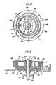
- a coil spring 128 is disposed in the cylinder 126 and its outer end is anchored in the peripheral wall of said cylinder 126 (via friction means 130 to avoid overload of said spring), while the inner end 132 is anchored in a sleeve 134 joined with a crown with inside teeth 136 and disposed to rotatably support cylinder 126.
- the crown with inside teeth 136 is so disposed as to correspond with one of the side ends of the cylinder 126 with which are engaged the teeth of a toothed wheel 138 rotatably supported by an eccentric 140 joined with shaft 94 of the draw roller 92.
- the group comprises the sleeve 134, and the crown with inside teeth 136 is rotatably supported by shaft 94 of the draw roller 94, and said shaft is torsionally bound with the cylinder 126 of the spring 128 via a unidirectional clutch member 130, which will be later described.
- the toothed crown 136, wheel 138, and eccentric 140 which engages the walls of a mounted aperture 142 in a swinging plate 144 provide an epicyclic set of wheels with a high reducing ratio; assuming in the illustrated case that the numbers of teeth of the crown 138 and the wheel 138 are respectively 60 and 58, it is possible to obtain a reducing ratio of 1:30, so that when eccentric 140 turns 30 times, cabinet 126 and, consequently, spring 128 are loaded for one rotation.
- Wheel 138 which constitutes the satellite of the epicyclic set of wheels, presents on its free surface a rod 145, which engages the radial apertures provided either in plate 144 or in support plate E 2 .
- Such plate 144 is held between wheel 138 and the outer surface of the support plate E 2 .
- plate 144 in a position orthogonal to the axis of rod 145 presents two other rods 146 which engage respective apertures provided in the support plate E 2 , to prevent, on one side, the rotation of the group: wheel 138-plate 144-and permit, on the other side, the transmission movement of said wheel 138.
- Cylinder 126 is forcibly closed by a cover 148, which thus supports a coil spring 128 during the loading and which torsionally communicates with the draw roller 92, according to a predetermined direction of rotation of the latter.
- a unidirectional joint 130 between shaft 94 of said draw roller 92 and sleeve 134 of spring 128, there is provided a unidirectional joint 130.
- Such joint is provided by a coil spring 150, whose coils flexibly engage a countersleeve 152, dovetailed in shaft 94 of the draw roller 92, the free end 154 being attached to cover 144, 148 of cylinder 126, thereby to determine the unidirectional torsional bond between shaft 94 and the end 132 of the coil spring 128.
- the operative bond between the draw roller and the being formed roll B 1 is provided by the weight of such roll being formed. Guiding from roll A l is carried out by providing the wind-up roll 160 with pivots 162, which extend in slots 164 longitudinally provided in bars 166, laterally attached to support plates E 1 and E 2 .
- slots 164 Downwardly, the slots 164 are closed and upwardly are open, and the front edges of the same are joined with inclined planes with slots 168, extending toward the aperture of the cover A 2 .
- slots 164 are so oriented as to have their median longitudinal axis to be substantially tangential to the draw roller 92, and upwardly to intersect the extension of the vertical diameter of the unwinding roll B 2 .
- devices F 1 , F 2 , F 3 , and F 4 are embodied in members stationarily supported by support plates E 1 and E 2 , which are interconnected; expediently, they form a frame stationarily attached to the base plate A 1 of the cabinet A by means of stationary joining members E 3 and E 4 , provided between said members.
- the end of the unwound toweling B is downwardly extended by a suitable length and such as to form the loop B 6 and the end B 7 of such loop is threaded through the slot 38 at the rear of the cabinet A and threaded between two guide bars 156 and 158.
- the wind-up roll 160 has its pivots 162 engaging grooved rods 166, and the initial length B 8 of the end B 7 of the toweling is attached in the already described manner to said wind-up roll 160, which engages the periphery of the subjacent draw roller 92.
- container A3 is lifted by flexible teeth 32 engaging windows 30 to close the cover A 2' which entails the locking of latches 20-26-28 ( Figure 7) of the lock D.
- the closing of cover A 2 engages the pairs of ribs 50-52 and 52-64 with the length of toweling B 5 and actuates the two sensing means 54-55 and 56-58.
- the apparatus A is ready to function and make available to the user a length of toweling B comprising the loop B 6 which is continuously renewed.
- the user pulls the length B 5 of the loop B 6 downwardly, first to disengage rod 56 of the sensing means 56-58 from the pair of ribs 52-64 and successively rotate the draw roller 42 in the clockwise direction.
- Device F 3 comprises wheels 80, 82, 84, 90 which actuate either the draw roll 92 of the roll B 1 or the loading of coil spring 128. More particularly, the rotation of the cam 140 integral with. shaft 94 of the planetary gear system 136-138 imparts a differential rotation between the roller 92 and sleeve 134 which holds the end 132 of spring 128, thus charging coil spring 128. This is because the cylinder 126 is prevented by pawl 116 held in engagement with teeth 124 from rotating from the position of rod 54 of the sensing means 54-55 uplifted from toweling B 5 sliding over the surface of the pair of ribs 50-52.
- the structure of the described and illustrated apparatus is simple and expedient, inasmuch as the different parts of the apparatus; and particularly wheel system of devices F l , F 2 , and F 3 and cabinet A, can be made of pressed plastic materials.
- container A3 can be of transparent material, thus to make visible the remaining supply of toweling of roll B 2'
- the draw rollers 42 and 92 provide their surfaces for engaging the toweling B formed expediently rough and rugged to ensure the adherence of the toweling and thereby the rotation of the rolls, even if the user draws loop B 6 in some unpredictable and unsymmetrical way relative to the width of toweling B.
- the device of double sensing F 4 can be so constructed as to control the winding up and the unwinding of the toweling B from roll B 2 into roll B 1 via servo controls, thus to limit the force of pull exerted by the user on loop B 6 of the toweling; for example, rod 56 of the second sensing means 56-58 can actuate interrupting contacts of a feed circuit of a suitable motor which controls the action of roller 92 and loads coil spring 126, thereby to withdraw in cabinet A the end length of roll B 2 .
Landscapes
- Health & Medical Sciences (AREA)
- Public Health (AREA)
- Unwinding Webs (AREA)
- Orthopedics, Nursing, And Contraception (AREA)
Applications Claiming Priority (2)
| Application Number | Priority Date | Filing Date | Title |
|---|---|---|---|
| IT20064/81A IT1167526B (it) | 1981-02-27 | 1981-02-27 | Apparecchio per controllare l'avvolgimento e lo svolgimento di bobine di nastri usati come asciugamani e simili |
| IT2006481 | 1981-02-27 |
Publications (2)
| Publication Number | Publication Date |
|---|---|
| EP0059893A2 true EP0059893A2 (de) | 1982-09-15 |
| EP0059893A3 EP0059893A3 (de) | 1983-01-26 |
Family
ID=11163519
Family Applications (1)
| Application Number | Title | Priority Date | Filing Date |
|---|---|---|---|
| EP82101456A Withdrawn EP0059893A3 (de) | 1981-02-27 | 1982-02-25 | Gerät zum Steuern des Auf- und Abwickelns von Handtuchstoffrollen oder dgl. |
Country Status (9)
| Country | Link |
|---|---|
| EP (1) | EP0059893A3 (de) |
| DE (1) | DE59893T1 (de) |
| DK (1) | DK84882A (de) |
| ES (1) | ES509970A0 (de) |
| FI (1) | FI820694A7 (de) |
| GR (1) | GR75516B (de) |
| IT (1) | IT1167526B (de) |
| NO (1) | NO820601L (de) |
| PT (1) | PT74493B (de) |
Cited By (5)
| Publication number | Priority date | Publication date | Assignee | Title |
|---|---|---|---|---|
| EP0138562A3 (en) * | 1983-10-14 | 1985-06-19 | Steiner Company International S.A. | A towel dispensing apparatus for making externally available and recovering a length of towel |
| EP0250256A3 (en) * | 1986-06-20 | 1988-07-20 | Duskin Co. Ltd. | Towel dispenser |
| WO1996000516A1 (de) * | 1994-06-28 | 1996-01-11 | Erich Schumm Gmbh | Handtuchspender für rollen-handtücher |
| EP1053712A1 (de) | 1999-05-21 | 2000-11-22 | Steiner Company International S.A. | Handtuchspender mit einer kontinuierlichen Bahn |
| EP1066785A1 (de) * | 1999-07-05 | 2001-01-10 | Cws International Ag | Steuerungsvorrichtung und deren Verwendung |
Families Citing this family (2)
| Publication number | Priority date | Publication date | Assignee | Title |
|---|---|---|---|---|
| US3833067A (en) * | 1972-10-30 | 1974-09-03 | Deere & Co | Spring biased scraper for disk implements |
| US4679635A (en) * | 1985-10-28 | 1987-07-14 | Fields Eddie L | Self-tripping rippers |
Family Cites Families (3)
| Publication number | Priority date | Publication date | Assignee | Title |
|---|---|---|---|---|
| US3563623A (en) * | 1969-05-15 | 1971-02-16 | Richard Rhodes Walton | Rotational energy storage and delivery devices |
| US3858951A (en) * | 1972-03-29 | 1975-01-07 | Georgia Pacific Corp | Towel dispenser |
| US3893738A (en) * | 1973-04-30 | 1975-07-08 | Steiner American Corp | Retractable towel cabinet |
-
1981
- 1981-02-27 IT IT20064/81A patent/IT1167526B/it active
-
1982
- 1982-02-25 EP EP82101456A patent/EP0059893A3/de not_active Withdrawn
- 1982-02-25 NO NO820601A patent/NO820601L/no unknown
- 1982-02-25 DE DE198282101456T patent/DE59893T1/de active Pending
- 1982-02-26 PT PT74493A patent/PT74493B/pt unknown
- 1982-02-26 GR GR67432A patent/GR75516B/el unknown
- 1982-02-26 DK DK84882A patent/DK84882A/da not_active Application Discontinuation
- 1982-02-26 FI FI820694A patent/FI820694A7/fi not_active Application Discontinuation
- 1982-02-26 ES ES509970A patent/ES509970A0/es active Granted
Cited By (7)
| Publication number | Priority date | Publication date | Assignee | Title |
|---|---|---|---|---|
| EP0138562A3 (en) * | 1983-10-14 | 1985-06-19 | Steiner Company International S.A. | A towel dispensing apparatus for making externally available and recovering a length of towel |
| EP0250256A3 (en) * | 1986-06-20 | 1988-07-20 | Duskin Co. Ltd. | Towel dispenser |
| WO1996000516A1 (de) * | 1994-06-28 | 1996-01-11 | Erich Schumm Gmbh | Handtuchspender für rollen-handtücher |
| US5820231A (en) * | 1994-06-28 | 1998-10-13 | Erich Schumm Gmbh | Towel dispenser for roll toweling |
| EP1053712A1 (de) | 1999-05-21 | 2000-11-22 | Steiner Company International S.A. | Handtuchspender mit einer kontinuierlichen Bahn |
| EP1066785A1 (de) * | 1999-07-05 | 2001-01-10 | Cws International Ag | Steuerungsvorrichtung und deren Verwendung |
| WO2001001837A1 (de) * | 1999-07-05 | 2001-01-11 | Cws International Ag | Steuerungsvorrichtung und deren verwendung |
Also Published As
| Publication number | Publication date |
|---|---|
| DK84882A (da) | 1982-08-28 |
| NO820601L (no) | 1982-08-30 |
| PT74493B (en) | 1983-08-17 |
| FI820694L (fi) | 1982-08-28 |
| DE59893T1 (de) | 1983-04-28 |
| ES8303068A1 (es) | 1983-02-01 |
| PT74493A (en) | 1982-03-01 |
| ES509970A0 (es) | 1983-02-01 |
| FI820694A7 (fi) | 1982-08-28 |
| IT1167526B (it) | 1987-05-13 |
| IT8120064A0 (it) | 1981-02-27 |
| GR75516B (de) | 1984-07-25 |
| EP0059893A3 (de) | 1983-01-26 |
Similar Documents
| Publication | Publication Date | Title |
|---|---|---|
| US4552315A (en) | Rolled web dispenser | |
| US4203562A (en) | Flexible sheet material dispensing of rolls in succession | |
| US3288387A (en) | Paper towel dispenser | |
| US4487375A (en) | Roll transfer mechanism for web material dispenser | |
| US5375920A (en) | Handtowel dispenser | |
| US5833104A (en) | Ticket dispensing device | |
| US3810591A (en) | Dispensing machine for coil stock | |
| EP0059893A2 (de) | Gerät zum Steuern des Auf- und Abwickelns von Handtuchstoffrollen oder dgl. | |
| US5244263A (en) | Continuous towel cabinets | |
| EP0288211B1 (de) | Ausgeber für eine Handtuchbahn | |
| US4818042A (en) | Cloth towel dispenser and method for the operation thereof | |
| US2957636A (en) | Towel dispensing apparatus | |
| AU608059B2 (en) | Improved web-dispensing apparatus | |
| US2946587A (en) | Towel dispenser | |
| JPH02213582A (ja) | 巻上げ装置 | |
| US20020145364A1 (en) | Towel loop formation in a hand towel dispenser | |
| US3506320A (en) | Apparatus for dispensing towelling | |
| US6766976B2 (en) | Dispenser for rolls of web material | |
| US3522978A (en) | Hand towel dispensing appliance | |
| EP0839014B1 (de) | Handtuchspender | |
| US1479864A (en) | Towel cabinet | |
| SU298103A1 (ru) | УСТРОЙСТВО дл ВЫДАЧИ СУХОГО ПОЛОТЕНЦА | |
| JP2003503131A (ja) | ハンドタオルディスペンサ | |
| NO844084L (no) | Haandkleutmatningsanordning hvor en viss lengde av haandkleet gjoeres tilgjengelig og foeres tilbake i anordningen | |
| JPS60144266A (ja) | タオル配与機 |
Legal Events
| Date | Code | Title | Description |
|---|---|---|---|
| PUAI | Public reference made under article 153(3) epc to a published international application that has entered the european phase |
Free format text: ORIGINAL CODE: 0009012 |
|
| AK | Designated contracting states |
Designated state(s): AT BE CH DE FR GB LU NL SE |
|
| PUAL | Search report despatched |
Free format text: ORIGINAL CODE: 0009013 |
|
| AK | Designated contracting states |
Designated state(s): AT BE CH DE FR GB LI LU NL SE |
|
| DET | De: translation of patent claims | ||
| 17P | Request for examination filed |
Effective date: 19830426 |
|
| STAA | Information on the status of an ep patent application or granted ep patent |
Free format text: STATUS: THE APPLICATION IS DEEMED TO BE WITHDRAWN |
|
| 18D | Application deemed to be withdrawn |
Effective date: 19841103 |
|
| RIN1 | Information on inventor provided before grant (corrected) |
Inventor name: CASSIA, ANTONIO MACCHI |