EP0059901B2 - Microprocessor-controlled device for a rotatable, extendable ladder or similar lifting arm - Google Patents
Microprocessor-controlled device for a rotatable, extendable ladder or similar lifting arm Download PDFInfo
- Publication number
- EP0059901B2 EP0059901B2 EP82101486A EP82101486A EP0059901B2 EP 0059901 B2 EP0059901 B2 EP 0059901B2 EP 82101486 A EP82101486 A EP 82101486A EP 82101486 A EP82101486 A EP 82101486A EP 0059901 B2 EP0059901 B2 EP 0059901B2
- Authority
- EP
- European Patent Office
- Prior art keywords
- microprocessor
- control
- movements
- ladder
- reach
- Prior art date
- Legal status (The legal status is an assumption and is not a legal conclusion. Google has not performed a legal analysis and makes no representation as to the accuracy of the status listed.)
- Expired - Lifetime
Links
- 230000033001 locomotion Effects 0.000 claims abstract description 127
- 230000015654 memory Effects 0.000 claims abstract description 39
- 125000004122 cyclic group Chemical group 0.000 claims abstract description 11
- 238000013459 approach Methods 0.000 claims abstract description 7
- 239000012190 activator Substances 0.000 claims abstract 4
- 230000004913 activation Effects 0.000 claims abstract 3
- 238000012937 correction Methods 0.000 claims description 15
- 238000005259 measurement Methods 0.000 claims description 15
- 230000001133 acceleration Effects 0.000 claims description 3
- 230000004044 response Effects 0.000 claims description 3
- 230000003213 activating effect Effects 0.000 claims description 2
- 230000002747 voluntary effect Effects 0.000 claims description 2
- 230000006870 function Effects 0.000 abstract description 12
- 238000010586 diagram Methods 0.000 description 22
- 235000021183 entrée Nutrition 0.000 description 10
- 238000011161 development Methods 0.000 description 8
- 238000012360 testing method Methods 0.000 description 8
- 239000000872 buffer Substances 0.000 description 7
- 230000000750 progressive effect Effects 0.000 description 7
- 238000012549 training Methods 0.000 description 6
- 230000008859 change Effects 0.000 description 5
- 230000035939 shock Effects 0.000 description 5
- 230000006978 adaptation Effects 0.000 description 4
- 238000012546 transfer Methods 0.000 description 4
- 238000012545 processing Methods 0.000 description 3
- 239000003381 stabilizer Substances 0.000 description 3
- 238000012795 verification Methods 0.000 description 3
- 230000003936 working memory Effects 0.000 description 3
- 230000002950 deficient Effects 0.000 description 2
- 230000007257 malfunction Effects 0.000 description 2
- 238000000034 method Methods 0.000 description 2
- 230000008569 process Effects 0.000 description 2
- 230000000284 resting effect Effects 0.000 description 2
- 230000011664 signaling Effects 0.000 description 2
- 241001415961 Gaviidae Species 0.000 description 1
- 241001080024 Telles Species 0.000 description 1
- 230000009471 action Effects 0.000 description 1
- 230000003321 amplification Effects 0.000 description 1
- 238000005452 bending Methods 0.000 description 1
- 230000008901 benefit Effects 0.000 description 1
- 230000008033 biological extinction Effects 0.000 description 1
- 230000005540 biological transmission Effects 0.000 description 1
- 230000000295 complement effect Effects 0.000 description 1
- 230000003247 decreasing effect Effects 0.000 description 1
- 238000006073 displacement reaction Methods 0.000 description 1
- 230000000694 effects Effects 0.000 description 1
- 238000009434 installation Methods 0.000 description 1
- 238000004519 manufacturing process Methods 0.000 description 1
- 230000005055 memory storage Effects 0.000 description 1
- 238000012986 modification Methods 0.000 description 1
- 230000004048 modification Effects 0.000 description 1
- 238000012544 monitoring process Methods 0.000 description 1
- 230000003472 neutralizing effect Effects 0.000 description 1
- 238000003199 nucleic acid amplification method Methods 0.000 description 1
- 230000003287 optical effect Effects 0.000 description 1
- 230000009467 reduction Effects 0.000 description 1
- 230000002441 reversible effect Effects 0.000 description 1
- 238000011076 safety test Methods 0.000 description 1
- 230000006641 stabilisation Effects 0.000 description 1
- 238000011105 stabilization Methods 0.000 description 1
- 230000001629 suppression Effects 0.000 description 1
- 239000000725 suspension Substances 0.000 description 1
Images


Classifications
-
- E—FIXED CONSTRUCTIONS
- E06—DOORS, WINDOWS, SHUTTERS, OR ROLLER BLINDS IN GENERAL; LADDERS
- E06C—LADDERS
- E06C5/00—Ladders characterised by being mounted on undercarriages or vehicles Securing ladders on vehicles
- E06C5/32—Accessories, e.g. brakes on ladders
- E06C5/36—Safety devices against slipping or falling of ladders; Safety devices against overloading ladders
-
- B—PERFORMING OPERATIONS; TRANSPORTING
- B66—HOISTING; LIFTING; HAULING
- B66C—CRANES; LOAD-ENGAGING ELEMENTS OR DEVICES FOR CRANES, CAPSTANS, WINCHES, OR TACKLES
- B66C23/00—Cranes comprising essentially a beam, boom, or triangular structure acting as a cantilever and mounted for translatory of swinging movements in vertical or horizontal planes or a combination of such movements, e.g. jib-cranes, derricks, tower cranes
- B66C23/88—Safety gear
- B66C23/90—Devices for indicating or limiting lifting moment
- B66C23/905—Devices for indicating or limiting lifting moment electrical
Definitions
- the present invention relates to a control device including the control and the safety of the movements of a ladder, such as for example a rescue and fire fighting ladder, or of a similar lifting arm mounted on a vehicle.
- Analog electronic control devices are known based on the following principle: an index symbolizes on a diagram the position of the end of the elevator and allows, thanks to a suitable coordinate axis system, the reading of the functional parameters.
- This index comprises a conductive part of the electric current which, during the movement of the index, switches electrically with the different zones of the diagram, themselves conductive and generally produced in the form of printed circuits. Switching with these zones produces the lighting or extinction of warning lights and possibly the automatic stop of movements when these become dangerous, in particular for the stability of the carrier vehicle.
- These devices are generally associated with an analog electromechanical or electronic logic system, which generates from information received from different sensors and the moving index, orders causing the change of state of indicators, the triggering of alarm (s) sound (s) or devices acting on the execution of movements.
- English patent application 2 050 294 relates generally to a steerable crane control involving a microprocessor, sensors of certain operating parameters, and comparisons with a table of limit data stored in memory, in order to trigger before exceeding these, an alarm and / or safety stop command for the crane movement.
- This must be regarded as a state of the art to which also relates the German patent application 2,836,337 as well as the European patent application 0 008 210.
- the English patent application 2 050 294 relates essentially (rev. 1) to a particular use of operating parameter to determine by calculation the actual working state of the boom (length and bending).
- the safety stop phase is provided for by a simple movement cut-off by relay (see description and claim 4).
- European patent application 0 008 210 relates essentially to an arrangement of optical encoders for processing the picked-up operating parameters chosen with a view to their processing and comparison with limit data.
- German patent application 2 836 337 relates to the joint use of two chains of different security parameters (double security) tested separately by a microcomputer intended to give only an alarm in the event of a fault indicated by one of the monitoring chains , and to continue the operation of the crane as long as the other chain does not in turn give contrary indication.
- German patent application no. 20 33 469 relates to the control of a scale on the basis of a measurement of the real torque and of a comparison of this real torque with a predetermined maximum torque.
- control device of the invention for a deployable orientable ladder, or similar lifting arm, provided with an articulated platform suitable for transporting one or more people comprises at least one raising or lowering control, a deployment and folding control and a pivoting control with members for manual selection of the desired movements, straightening and lowering, deployment and folding, and pivoting actuators, said selection members being adapted to supply representative electrical signals direction of control and the desired speed of execution of the desired movements.
- the device comprises a microprocessor reader of the control signals receiving said electrical signals.
- Said microprocessor comprises in memory: the maximum ranges not to be exceeded as a function of various selectable and predetermined parameters for bringing the scale into service, including choices of predetermined loads and predetermined scale orientations; a sequence of cyclic calculation of the actual range from information given by sensors for measuring the angle of training and the length deployed; a cyclic comparison sequence of the real range calculated with the maximum range corresponding to the predefined implementation conditions and whether or not authorizing the requested movement.
- Said microprocessor further includes in memory a law for decelerating the lowering and deployment movements at least, in predetermined terminal zones of evolution of these movements corresponding to a certain approach to the maximum predetermined range of use corresponding to the case of 'the use of the scale, taking into account the choice of load made by the user, said end zones being limited by said predetermined maximum operating range and being constantly recalculated by the microprocessor during movement.
- the microprocessor also includes in memory a cyclic comparison sequence, in this approach, of the displayed control speed with the speed derived from said law for each movement considered, intended to impose said law when the displayed control speed is excessive, by providing at the outputs of the microprocessor controlling these movements of the signals representative of the displayed control speed or automatically modified according to said law to reach the maximum predetermined range at zero speed; said outputs being connected to proportional electrical control members for activating the actuators of the movements considered.
- microprocessor control also makes it possible to limit the acceleration on switching on and off in response to orders for voluntary commands to switch on or off, by means of predetermined laws stored in memory.
- Such a command also lends itself to the digital display of the operating parameters with as high a precision as desired, whether in particular the current parameters or operating limits.
- Reaching the operating limit marked by the abovementioned automatic stopping process can also be advantageously accompanied by assistance with subsequent piloting by sending a spoken message indicating to the pilot the solution or solutions remaining at his disposal.
- Such a microprocessor control also has the advantage of being easily adaptable to all options of equipment of the equipment and of changes of the limits for which it suffices to modify the data taken into memory.
- the microprocessor also allows the command and automatic control of the horizontal alignment of the platform floor according to the angle of the ladder.
- a scale movement control and safety system aims to provide the user with the value of the operating parameters such as the angle of dressing ⁇ , the developed length L, the maximum possible load at the end of the ladder, the height reached H, the range P ... to alert the user and possibly stop the movements when they become dangerous, in particular in the event of an impact with an obstacle or in the event of being reached vehicle stability limits.
- This figure 3 symbolizes the usage diagrams corresponding to three possible positions of the support cylinders, but a continuous variation of the diagram can be envisaged.
- the different limits are stored in the control system.
- the control system compares the position of the ladder to each of the limits and lights up an indicator which corresponds to the possibility of maximum load. Automatic deployment, lowering and possibly pivoting movements are stopped when the ladder fitted with its rescue platform reaches the limit corresponding to the load case a1, a2, and a3, or when the ladder without rescue platform reaches the limit corresponding to a4, or the limits going from a'1 to a'4 or from a''1 to a''4 depending on the position of the beams 3.
- an audible device is activated to attract the attention of the user.
- a sensor When the rescue platform is used, a sensor signals its presence.
- Switches allow you to select the limits: two men plus platform, one man plus platform. Before reaching the usage limit corresponding to the chosen load case, a pre-signal intervenes as well as a slowing down of the maneuvers as will be seen below.
- the scale position information delivered by the various sensors is read periodically by the microprocessor and stored in memory.
- the microprocessor processes this data and compares the state of the scale with the limits of use stored in permanent memory.
- the microprocessor causes the automatic stop of this movement when the limit is reached, but after having achieved a progressive deceleration of the movement until the total stop and this whatever the command order given by the operator as we will see later.
- the program plans to initialize the memory boxes in RAM.
- the MPU via the data BUS, by exciting the corresponding addresses, allows the transfer of REPROM to RAM of the initialization parameters.
- All digital inputs E1 to E34 are present as 1 or 0 at the terminals of the input BUFFERS.
- the MPU thanks to the addresses of the input PIA 1 and BUFFER 1, reads all of the inputs E1 to E16 which must be transferred to RAM by the BUS of the data and the memory addresses.
- All analog inputs E41 to E51 are present as a voltage across the terminals of analog input multiplexers.
- the MPU thanks to the addresses of the PIA 1, the multiplexer 1 and the A / D converter, reads the input E41, converted into digital and transfers by the BUS data and the address of the memory, the corresponding binary word in the RAM.
- the MPU When all the external data is in RAM memory, the MPU performs the calculations necessary for the smooth running of the program by going to draw from RAM by the data BUS and addresses the previously stored data.
- the display of the training angle, developed length, span and height parameters is done via the data buses and addresses of the PIA 2, the digital display decoder, and a 7-segment decoder for each digital output. , i.e. for S25 to S32 in a row.
- the MPU on each cycle, reads all the logic and analog inputs that it stores in RAM at the same addresses as before, the parameters already stored being automatically erased.
- the MPU performs all the calculations with this new information and the elements displayed are possibly updated.
- certain data are only displayed every 2 seconds for example.
- the MPU completes the program in a few milliseconds. This time is variable depending on the number of movements performed. In any event, each of the scale control parameters is read approximately 200 times per second.
- Self-checking of the inputs is included in the programs; for example, in measurements, if two successive readings of an analog input give a large deviation, the new value is not validated and other measurements are made. If this fault persists, the MPU, by displaying the number assigned to the faulty sensor, signals this incident and possibly stops the normal operation of the scale.
- the MPU checks whether the value of the analog input E47 (Measurement of the developed length) believes, if not, as previously, the reading of the input E47 is carried out several times, and if the anomaly persists, there is display of the number assigned to the sensor E47 and the operation of the ladder.
- the system thus performs a self-check and avoids giving erroneous orders in the event that it receives false information.
- the microprocessor also controls the display and signaling panel which informs the user about the state of the scale and its possibilities.
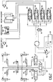
- Figure 7 shows the block diagram of the hydraulic movement control circuit.
- a variable flow pump 52 supplies the entire installation from a reservoir 53.
- the telescopic beams which support the chocks are controlled by distributors 54 and 55 which respectively supply the jacks 56 of the left beams and the cylinders 57 of the right beams.
- a distributor 58 ensures the actuation of cylinders 59 for neutralizing the elastic suspension of the vehicle and of the timing cylinders 2.
- a pressure switch 60 registers the resulting pressure increase and it establishes the energizing the electronic system of the ladder via input E1. Therefore, the control of the movements of the scale itself is possible by action on the proportional solenoid valves 61, 62, 63 and 64.
- the solenoid valve 61 controls the deployment-folding movement through the hydraulic motor 65 which actuates a winch.
- the solenoid valve 62 controls the dressing-lowering movement by means of the jacks 66.
- the solenoid valve 63 feeds the tilt correction cylinders 67 which cause the part 5 of the turret to rotate.
- the solenoid valve 64 controls the pivoting movement to the right or to the left by means of the motor 68.
- Each of the solenoid valves 61, 62, 63, 64 is of the proportional type, that is to say it delivers a flow proportional to the control voltage of the coils.
- the microprocessor cuts the electrical supply to the distributor 51, output S19 of the microprocessor (control oil pressure of the pump at zero value by exit status 0).
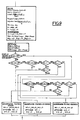
- FIG. 8 shows the general flowchart of the operations carried out by the electronic microprocessor system.
- the program then includes the scale overload test (Input E51).
- the program then includes the successive control of the different movements:
- the principle of movement control is the same for all movements except the folding back, for which the automatic concordance of the steps can be superimposed.
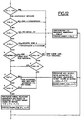
- Figures 9, 10 and 11 show the detailed flowchart for the calculation of heights and spans, the memorization of the position of the support beams of the stabilizer jacks, the display of the authorized load limits and the storage of the limit range corresponding to the operating case.
- the microprocessor after having read all the input parameters, calculates the range P, the height H, the maximum values of developable length L maxi before automatic stop at constant angle of dressing and corresponding maximum height H, the maximum value of the dressing angle ⁇ 2 corresponding to the maximum range for which there must be an automatic stop at constant developed length L; the angle of dressing ⁇ r, the range Pr and the developed length Lr at the start of slowing down of the movements.
- ⁇ corresponds to an angular range of deceleration of the lowering before automatic stop
- ⁇ P and ⁇ L to two ranges of deceleration before automatic stop in range or developed length.
- the different values taken into account are stored in memories indicated in the “Calculation” box of FIG. 9, by the letter M followed by an identification index.
- the microprocessor uses the memory M20 in which the maximum range corresponding to the use of the scale is stored (fig. 3 and 11).
- the microprocessor then checks in what position the timing cylinders 2 are and what is the orientation ⁇ of the scale relative to the longitudinal axis of the vehicle. If the orientation ⁇ of the scale does not differ by more than ⁇ 25 ° from the longitudinal axis of the vehicle, the useful range is the maximum range for the load considered and it is independent of the position of the stabilizers. For different orientations of the scale, the microprocessor memorizes the position of the beams located on the side where the scale is oriented (memories M2, M3, M4, fig. 9).
- the microprocessor then displays the load case (fig. 10). It examines whether the ladder is used with or without its platform (entry E9) what is the choice of load made by the user (1, 2 or 3 men on the platform, resting ladder, entries E10, E11, E12) and it compares, in the case of the scale used without a platform, the actual range of the scale stored in the memory M21, with the limit ranges authorized as a function of the position of the stabilizers; it deduces the maximum possible load therefrom and proceeds to switch on the corresponding warning light and extinguish the other warning lights by outputs S3 to S9 (warning lights 33 to 39).
- the microprocessor then checks if there is a concordance of steps and displays the corresponding display (LED 41).
- the following sequence relates to the emission of an audible signal when there is a change of load case; thus an audible signal of duration 1 second is emitted when the range becomes equal to P4, P5, P6, P7, P8 or P9.
- FIG. 12 The operating principle of motion control is described using FIG. 12, taking the example of the lowering of the scale (with analog signals in the form of voltage).
- the operator via a Dressage / Lowering control manipulator, requests the lowering of the scale and sends a voltage proportional to the requested speed to the electronic system.
- the command and control system checks whether the requested movement can be executed according to the various safety parameters entered in the program and generates, if there is compatibility, the control signal (output S33) which will be taken into account by the solenoid valve (62) for controlling the movement in question.
- the MPU sets the output S33 to 0 (or maintains it if it was previously there).
- the MPU checks, in the order of the program, the logical values of the inputs E18, E25 and E29 (stored in RAM). If one of them is at 1, the output S33 is set (or maintained) at 0.
- test A and B the verification of the position of the ladder in relation to the pivoting and straightening / lowering chassis to avoid any interference with the vehicle cabin.
- test C is done.
- the analog output S33 generates a signal proportional to the input E41 with a decreasing maximum value in accordance with a deceleration curve with end of travel stop, REPROM memory storage and which will be seen later.
- the MPU checks logic input E27 (test D) and test E.
- the output S33 If D or E is positive, the output S33 generates, as above, a signal proportional to the input E41 with maximum value limited by said deceleration curve before end of travel.
- the MPU If D and E are negative, the MPU generates a signal proportional to the input E41 without correction except in the event of a sudden request or suppression of the motion control (input E41) or in this case the MPU generates the output signal at l acceleration and deceleration, according to other speed control curves stored in REPROM memory, this in order to have greater comfort in piloting the ladder and to avoid unpleasant mechanical stresses on the ladder.
- the MPU which manages the output S33 can, without waiting for a deviation from the horizontality of the platform, simultaneously control its alignment by generating a proportional signal to S33 on the output S36: proportional control for horizontal positioning of the platform 11, this proportional control being able to cooperate with an actuator not shown, such as an electric actuator interposed between the last rung 10 of the scale and the platform to vary the angle ⁇ .
- a control loop is incorporated into the program, which allows, by measuring the angle ⁇ of the platform with respect to the scale (E45) to put in the program a correction parameter making it possible to remove the deviations due to the electro-hydro-mechanical system for controlling the power of the ladder's movements.
- the training command is controlled and executed by the MPU according to the same principle as the lowering command above, with of course, parameters to control specific to this movement.
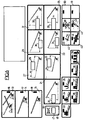
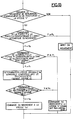
- FIG. 13 defines the principle flow diagram of the automatic slowing down of the pivoting, lowering or deployment movements before automatic stopping, corresponding to the maximum admissible range.
- the microprocessor receives the operator's movement orders. If the range P is greater than or equal to the maximum admissible range Pa, the microprocessor does not control the movement.
- the microprocessor compares the range P with the range Pr corresponding to the start of the zone where the movement must be slowed down in order to reach the automatic stopping point at zero speed.
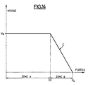
- Figure 14 illustrates the diagram of the speed of movement as a function of the space traveled.
- the speed of the movement is that requested by the operator and it can go up to the maximum speed Vm allowed by the control systems.
- zone B corresponding to a range P greater than Pr and less than Pa, the microprocessor imposes a maximum speed defined by the limit C which joins the point of start of deceleration where the speed can be maximum at the point of end of deceleration where the speed must be zero.
- zone B the microprocessor controls the movement at the speed requested by the operator as long as this is lower than the limit speed defined by curve C, then at the speed corresponding to this curve C when the speed requested by l operator becomes superior to the latter.
- a movement slowdown system is only effectively achievable thanks to the use of a microprocessor because the slowdown zones of each movement are a function of the large number of parameters on which the limit range Pa depends and they must be constantly recalculated in course of movement, as we have seen, the various movements of the scale being able to be simultaneous and influencing the limit range Pa.
- the microprocessor thus limits in all cases the harmful dynamic effects and in particular any swinging of the undesirable scale.
- the slowing down of the various movements can be controlled in the following manner by the microprocessor.
- the microprocessor calculates the maximum admissible speed for each movement corresponding to a progressive deceleration. For this, each movement is considered as if it were executed alone, this being possible only thanks to the very high calculation speed of the microprocessor.
- V Lm (N) V LMaxi [1- (1 / n1) x
- the microprocessor which has in memory the speed-command relation S34 of the development movement, determines the maximum command command S34 m which corresponds to the maximum admissible speed V Lm (N).
- V ⁇ m (R) V ⁇ Maxi [1- (1 / n2) x
- the microprocessor which has in memory the speed-command relationship S33 of the lowering movement determines the maximum command order S33 m which corresponds to the maximum admissible speed V ⁇ m (R).
- the range Pa corresponding to the automatic stop may change, for example when the scale deviates from the longitudinal axis of the vehicle and the beams of the jacks are retracted or half-extended.
- the microprocessor which has in memory the speed-command relation S35 of the pivoting movement, determines the maximum command command S35 m which corresponds to the maximum admissible speed V ⁇ m (T).
- FIG. 21 defines the principle flow diagram for the horizontal positioning of the working platform 11.
- the microprocessor simultaneously controls the angular movement of the platform and the raising or lowering of the ladder at the same speed.
- sensors of known types such as potentiometers or angular encoders measure the angle of dressing ⁇ and the angle ⁇ of the platform floor relative to the scale.
- the microprocessor calculates the speed necessary to follow the raising or lowering movement and to remove the position deviation after a defined time, for example 5 seconds.
- This device which performs the simultaneous angular movement of the platform 11 and of the ladder makes it possible to have the platform horizontally precise and smoothly, which improves the comfort of the passengers.
- the microprocessor When the operator requests a movement which becomes dangerous for the stability of the vehicle, the microprocessor thus causes, as explained, the automatic stopping of this movement when the limit is reached, after having achieved the progressive deceleration of this movement.
- the movement being stopped the light requesting training or folding back (S11 - light 45, fig. 6) lights up.
- the operator who may be in a context of panic, may not react immediately and wonder why the ladder is no longer ordered. It is then that the transmission of a spoken message takes on its full value and is here provided from the microprocessor according to the diagram in FIG. 22.
- the microprocessor at this time, sends by BUS, the information necessary for the dissemination of the message corresponding to the scenario that caused the automatic shutdown.
- the memory circuits 69 and speech synthesizer 70 manufacture the sentence to be broadcast which, after amplification at 71 is transmitted to a loudspeaker 72 placed near the ladder operator acting in the vehicle.
- a second listening station 73 can be placed at the ladder control station located in the platform 11 to inform an operator acting from the platform.
- microprocessor also allows greater ease of adaptation to particular constraints.
- the operating limits change and it suffices to modify the values stored in memory.
- modifications or options are requested in the security system, it suffices to add additional sensors if necessary and to modify the program. This means that many variants can be easily adapted while remaining within the scope of the invention.
Landscapes
- Engineering & Computer Science (AREA)
- Mechanical Engineering (AREA)
- Ladders (AREA)
- Programmable Controllers (AREA)
- Manipulator (AREA)
Abstract
Description
La présente invention est relative à un dispositif de commande incluant le controle et la sécurité des mouvements d'une échelle, telle que par exemple une échelle de sauvetage et de lutte contre l'incendie, ou de bras élévateur analogue monté sur véhicule.The present invention relates to a control device including the control and the safety of the movements of a ladder, such as for example a rescue and fire fighting ladder, or of a similar lifting arm mounted on a vehicle.
On connaît des dispositifs de commande électroniques analogiques basés sur le principe suivant : un index symbolise sur un diagramme la position de l'extrémité de l'élévateur et permet, grâce à un système d'axe de coordonnées adapté, la lecture des paramètres fonctionnels.Analog electronic control devices are known based on the following principle: an index symbolizes on a diagram the position of the end of the elevator and allows, thanks to a suitable coordinate axis system, the reading of the functional parameters.
Cet index comporte une partie conductrice du courant électrique qui effectue, lors du déplacement de l'index, une commutation électrique avec les différentes zones du diagramme, elles-mêmes conductrices et généralement réalisées sous forme de circuits imprimés. La commutation avec ces zones produit l'allumage ou l'extinction de voyants et éventuellement l'arrêt automatique des mouvements lorsque ceux-ci deviennent dangereux, notamment pour la stabilité du véhicule porteur.This index comprises a conductive part of the electric current which, during the movement of the index, switches electrically with the different zones of the diagram, themselves conductive and generally produced in the form of printed circuits. Switching with these zones produces the lighting or extinction of warning lights and possibly the automatic stop of movements when these become dangerous, in particular for the stability of the carrier vehicle.
Ces dispositifs sont généralement associés à un système logique analogique électromécanique ou électronique, qui génère à partir des informations reçues de différents capteurs et de l'index mobile, des ordres provoquant le changement d'état de voyants, le déclenchement d'avertisseur(s) sonore(s) ou de dispositifs agissant sur l'exécution des mouvements.These devices are generally associated with an analog electromechanical or electronic logic system, which generates from information received from different sensors and the moving index, orders causing the change of state of indicators, the triggering of alarm (s) sound (s) or devices acting on the execution of movements.
L'augmentation du nombre des paramètres de fonctionnement due notamment à l'utilisation de systèmes de stabilisation du véhicule à entr'axes des points d'appui variables, ainsi que la recherche d'une plus grande précision dans la mesure, le traitement et l'indication des paramètres de fonctionnement, rendent difficile la réalisation de systèmes analogiques simples et fiables.The increase in the number of operating parameters due in particular to the use of vehicle stabilization systems with axes of variable support points, as well as the quest for greater precision in the measurement, processing and indication of the operating parameters makes it difficult to produce simple and reliable analog systems.
La demande de brevet anglais 2 050 294 se rapporte de façon générale à une commande de grue orientable faisant intervenir un microprocesseur, des capteurs de certains paramètres de fonctionnement, et des comparaisons avec une table de données limites mises en mémoire, en vue de déclencher avant dépassement de ces dernières, une alarme et/ou commande d'arrêt de sécurité du mouvement de grue. Cela doit être regardé comme un état de la technique auquel se rattachent également la demande de brevet allemand 2 836 337 ainsi que la demande de brevet européen 0 008 210.
La demande de brevet anglais 2 050 294 porte pour l'essentiel (rev. 1) sur une utilisation particulière de paramètre de fonctionnement pour déterminer par calcul l'état réel de travail de la flèche (longueur et flexion). La phase d'arrêt sécurité y est prévue par une simple coupure de mouvement par relais (voir description et revendication 4).The
La demande de brevet européen 0 008 210 porte essentiellement sur un agencement de codeurs optiques pour traiter les paramètres captés de fonctionnement choisis en vue de leur traitement et comparaison avec des données limites.
La demande de brevet allemand 2 836 337 porte sur l'utilisation conjointe de deux chaînes de paramètres de sécurité différents (double sécurité) testés séparément par un microcalculateur destiné à donner seulement une alarme en cas de défaut indiqué par l'une des chaînes de surveillance, et à faire continuer le fonctionnement de la grue tant que l'autre chaîne ne donne pas à son tour d'indication contraire.
La demande de brevet allemand no. 20 33 469 concerne la commande d'une échelle à partir d'une mesure du couple réel et d'une comparaison de ce couple réel à un couple maximal prédéterminé.German patent application no. 20 33 469 relates to the control of a scale on the basis of a measurement of the real torque and of a comparison of this real torque with a predetermined maximum torque.
Dans aucune de ces demandes il n'est prévu, en combinaison avec un microprocesseur lecteur de signaux électriques représentatifs du sens et de la vitesse d'exécution des mouvements désirés, des dispositions permettant d'obtenir une décélération automatique de vitesse à l'approche de la portée limite d'utilisation correspondante.In none of these applications is it provided, in combination with a microprocessor reader of electrical signals representative of the direction and speed of execution of the desired movements, arrangements making it possible to obtain an automatic speed deceleration when approaching the corresponding limit of use.
Tel qu'il est revendiqué, le dispositif de commande de l'invention pour une échelle orientable déployable, ou bras élévateur analogue, muni d'une plateforme articulée propre à transporter une ou plusieurs personnes, comprend au moins une commande de dressage ou abaissement, une commande de déploiement et reploiement et une commande de pivotement à organes de sélection manuelle des mouvements désirés, des actionneurs de dressage et d'abaissement, de déploiement et reploiement, et de pivotement, lesdits organes de sélection étant adaptés pour fournir des signaux électriques représentatifs du sens de commande et de la vitesse désirée d'exécution des mouvements désirés.Selon l'invention, le dispositif comprend un microprocesseur lecteur des signaux de commande recevant lesdits signaux électriques. Ledit microprocesseur comprend en mémoire: les portées maximales à ne pas dépasser en fonction de divers paramètres sélectionnables et prédéterminés de mise en service de l'échelle, incluant des choix de charges prédéterminées et des orientations d'échelle prédéterminées; une séquence de calcul cyclique de la portée réelle à partir des informations données par des capteurs de mesure de l'angle de dressage et de la longueur déployée; une séquence de comparaison cyclique de la portée réelle calculée avec la portée maximale correspondant aux conditions de mise en oeuvre prédéfinies et autorisant ou non le mouvement demandé.As claimed, the control device of the invention for a deployable orientable ladder, or similar lifting arm, provided with an articulated platform suitable for transporting one or more people, comprises at least one raising or lowering control, a deployment and folding control and a pivoting control with members for manual selection of the desired movements, straightening and lowering, deployment and folding, and pivoting actuators, said selection members being adapted to supply representative electrical signals direction of control and the desired speed of execution of the desired movements. According to the invention, the device comprises a microprocessor reader of the control signals receiving said electrical signals. Said microprocessor comprises in memory: the maximum ranges not to be exceeded as a function of various selectable and predetermined parameters for bringing the scale into service, including choices of predetermined loads and predetermined scale orientations; a sequence of cyclic calculation of the actual range from information given by sensors for measuring the angle of training and the length deployed; a cyclic comparison sequence of the real range calculated with the maximum range corresponding to the predefined implementation conditions and whether or not authorizing the requested movement.
Ledit microprocesseur comprend en outre en mémoire une loi de décélération des mouvements d'abaissement et de déploiement au moins, dans des zones terminales prédéterminées d'évolution de ces mouvements correspondant à une certaine approche de la portée maximale d'utilisation prédéterminée correspondant au cas d'utilisation de l'échelle, compte tenu du choix de charge fait par l'utilisateur, lesdites zones terminales étant limitées par ladite portée maximale d'utilisation prédéterminée et étant recalculées constamment par le microprocesseur en cours de mouvement.Said microprocessor further includes in memory a law for decelerating the lowering and deployment movements at least, in predetermined terminal zones of evolution of these movements corresponding to a certain approach to the maximum predetermined range of use corresponding to the case of 'the use of the scale, taking into account the choice of load made by the user, said end zones being limited by said predetermined maximum operating range and being constantly recalculated by the microprocessor during movement.
Le microprocesseur comprend également en mémoire une séquence de comparaison cyclique, dans cette approche, de la vitesse de commande affichée avec la vitesse dérivée de ladite loi pour chaque mouvement considéré, destinée à imposer ladite loi lorsque la vitesse de commande affichée est excessive, en fournissant aux sorties du microprocesseur commandant ces mouvements des signaux représentatifs de la vitesse de commande affichée ou automatiquement modifiés en fonction de ladite loi pour atteindre la portée maximale prédéterminée à vitesse nulle; lesdites sorties étant connectées à des organes de commande électrique proportionnelle d'activation des actionneurs des mouvements considérés.The microprocessor also includes in memory a cyclic comparison sequence, in this approach, of the displayed control speed with the speed derived from said law for each movement considered, intended to impose said law when the displayed control speed is excessive, by providing at the outputs of the microprocessor controlling these movements of the signals representative of the displayed control speed or automatically modified according to said law to reach the maximum predetermined range at zero speed; said outputs being connected to proportional electrical control members for activating the actuators of the movements considered.
De plus, une telle commande à microprocesseur permet aussi de limiter l'accélération à la mise en marche et à l'arrêt en réponse aux ordres de commandes volontaires de mise en marche ou d'arrêt, par intervention de lois prédéterminées mises en mémoire.In addition, such a microprocessor control also makes it possible to limit the acceleration on switching on and off in response to orders for voluntary commands to switch on or off, by means of predetermined laws stored in memory.
Une telle commande se prête aussi à l'affichage numérique des paramètres de fonctionnement avec une précision aussi grande que souhaitée, qu'il s'agisse notamment des paramètres actuels ou limites de fonctionnement.Such a command also lends itself to the digital display of the operating parameters with as high a precision as desired, whether in particular the current parameters or operating limits.
L'atteinte de limite de fonctionnement marquée par le processus d'arrêt automatique précité peut aussi être avantageusement accompagnée d'une aide au pilotage ultérieur par émission d'un message parlé indiquant au pilote la ou les solutions restant à sa disposition.Reaching the operating limit marked by the abovementioned automatic stopping process can also be advantageously accompanied by assistance with subsequent piloting by sending a spoken message indicating to the pilot the solution or solutions remaining at his disposal.
Une telle commande à microprocesseur présente aussi l'intérêt d'être aisément adaptable à toutes options d'équipement du matériel et de changements des limites pour lesquelles il suffit de modifier les données prises en mémoire.Such a microprocessor control also has the advantage of being easily adaptable to all options of equipment of the equipment and of changes of the limits for which it suffices to modify the data taken into memory.
On sait qu'un microprocesseur se prête aussi à l'établissement aisé d'un programme d'autodiagnostic permettant notamment d'identifier le cas échéant les capteurs défectueux.It is known that a microprocessor also lends itself to the easy establishment of a self-diagnostic program making it possible in particular to identify defective sensors if necessary.
En outre, en cas d'équipement à plate-forme usuelle articulée à l'extrémité supérieure de l'échelle, le microprocesseur permet aussi la commande et le contrôle automatique de mise à l'horizontale du plancher de plate-forme en fonction de l'angle de dressage de l'échelle.In addition, in the case of equipment with the usual platform articulated at the upper end of the ladder, the microprocessor also allows the command and automatic control of the horizontal alignment of the platform floor according to the angle of the ladder.
Une forme de réalisation d'un dispositif de commande à microprocesseur pour échelle orientable déployable est d'ailleurs ci-après décrite à titre d'exemple illustratif de l'invention et en référence au dessin annexé, dans lequel :
- la figure 1 est une vue schématique d'une telle échelle sur véhicule indicative de ses paramètres de fonctionnement ;
- la figure 2 est une vue de côté de l'ensemble de l'échelle seule sur son véhicule ;
- la figure 3 est un diagramme des limites d'utilisation de l'échelle en fonction des différents paramètres de fonctionnement ;
- la figure 4 est un schéma général d'ensemble des entrées et sorties du microprocesseur ;
- la figure 5 représente la constitution générale du système électronique à microprocesseur ;
- la figure 6 représente un exemple de réalisation de tableau d'affichage ;
- la figure 7 est un schéma d'ensemble du système hydraulique de commande des divers mouvements de l'échelle ;
- la figure 8 est l'organigramme général des opérations exécutées par le microprocesseur ;
- la figure 9 est un organigramme détaillé des divers calculs effectués par le microprocesseur, de leur mémorisation et des affichages en découlant ;
- la figure 10 est un organigramme des divers affichages et signalisations d'information de l'utilisateur ;
- la figure 11 est un organigramme relatif aux diverses conditions d'utilisation et de portée de l'échelle ;
- la figure 12 est l'organigramme schématique de l'opération de contrôle d'un mouvement (mouvement d'abaissement pris en exemple) ;
- la figure 13 est l'organigramme de principe du ralentissement automatique des mouvements avant arrêt automatique ;
- la figure 14 est un diagramme de vitesse en fonction de l'espace pour l'un des mouvements de l'échelle ;
- les figures 15 et 16 sont des vues illustratives complémentaires d'un mode de ralentissement automatique progressif à plusieurs paliers contrôlé par le microprocesseur pour le mouvement de développement de l'échelle ;
- les figures 17 et 18 sont des vues illustratives complémentaires concernant le ralentissement automatique progressif du mouvement d'abaissement de l'échelle ;
- les figures 19 et 20 sont des vues illustratives complémentaires se rapportant au ralentissement automatique progressif du mouvement de pivotement de l'échelle ;
- la figure 21 est l'organigramme de principe de la commande automatique de mise à l'horizontale de la plate-forme ;
- la figure 22 est un schéma de principe du système d'émission de messages parlés.
- Figure 1 is a schematic view of such a scale on the vehicle indicative of its operating parameters;
- Figure 2 is a side view of the entire ladder alone on his vehicle;
- FIG. 3 is a diagram of the limits of use of the scale as a function of the different operating parameters;
- FIG. 4 is a general overall diagram of the inputs and outputs of the microprocessor;
- FIG. 5 represents the general constitution of the electronic microprocessor system;
- FIG. 6 represents an exemplary embodiment of a display board;
- FIG. 7 is an overall diagram of the hydraulic system for controlling the various movements of the ladder;
- FIG. 8 is the general flowchart of the operations executed by the microprocessor;
- FIG. 9 is a detailed flow diagram of the various calculations carried out by the microprocessor, of their storage and of the displays resulting therefrom;
- FIG. 10 is a flow diagram of the various displays and indications of user information;
- FIG. 11 is a flowchart relating to the various conditions of use and scope of the scale;
- FIG. 12 is the schematic flow diagram of the operation for controlling a movement (lowering movement taken as an example);
- FIG. 13 is the principle flow diagram of the automatic slowing down of the movements before automatic stopping;
- FIG. 14 is a diagram of speed as a function of space for one of the movements of the scale;
- FIGS. 15 and 16 are complementary illustrative views of a progressive automatic slowdown mode with several stages controlled by the microprocessor for the development movement of the ladder;
- FIGS. 17 and 18 are additional illustrative views concerning the progressive automatic slowing down of the ladder lowering movement;
- FIGS. 19 and 20 are additional illustrative views relating to the progressive automatic deceleration of the pivoting movement of the ladder;
- FIG. 21 is the flow diagram of the principle of the automatic control for horizontal adjustment of the platform;
- FIG. 22 is a block diagram of the system for transmitting spoken messages.
L'échelle sur véhicule représentée aux figures 1 et 2 est constituée :
- ― d'un châssis-
cabine 1 à quatre vérins de calage 2 qui assurent la stabilité du châssis pendant l'utilisation de l'échelle. Chacun des vérins est monté sur une poutresupport télescopique 3 qui permet d'ajuster le polygone d'appui à la place disponible autour du véhicule (distance d variable) ; - ― d'une tourelle d'orientation 4 qui peut pivoter par rapport au châssis (angle θ). Cette tourelle comporte en
outre une partie 5 articulée autour d'un axe horizontal 5a en vue de maintenir l'axe des éléments d'échelle dans un plan vertical passant par cet axe même lorsque le véhicule est incliné (dispositif de correction de dévers angle δ) ; - ― d'un
support d'échelle 6 appelé berceau articulé autour d'un axe horizontal 6a et qui permet de faire varier l'angle de dressage α de l'échelle de - 15° à + 75° ; - ― de quatre plans d'échelle télescopiques 7, 8, 9, 10 à développement simultané ;
- ― d'une plate-forme de sauvetage amovible 11 articulée en bout
du plan d'échelle 10suivant un axe 12 afin de pouvoir conserver l'horizontalité de son plancher pendant les mouvements de dressage ou d'abaissement (angle β).
- - a chassis-
cab 1 with four wedgingcylinders 2 which ensure the stability of the chassis during use of the ladder. Each of the jacks is mounted on atelescopic support beam 3 which makes it possible to adjust the support polygon to the space available around the vehicle (distance d variable); - - an
orientation turret 4 which can pivot relative to the chassis (angle θ). This turret further comprises apart 5 articulated around a horizontal axis 5a in order to maintain the axis of the ladder elements in a vertical plane passing through this axis even when the vehicle is tilted (tilt angle correction device δ); - - a
ladder support 6 called a cradle articulated around a horizontal axis 6a and which makes it possible to vary the dressing angle α of the scale from - 15 ° to + 75 °; - - four telescopic ladder planes 7, 8, 9, 10 for simultaneous development;
- - a
removable rescue platform 11 articulated at the end of theladder plane 10 along anaxis 12 in order to be able to maintain the horizontality of its floor during the dressing or lowering movements (angle β).
Un système de contrôle et de sécurité des mouvements de l'échelle a pour but de fournir à l'utilisateur la valeur des paramètres de fonctionnement tels que l'angle de dressage α, la longueur développée L, la charge maximale possible à l'extrémité de l'échelle, la hauteur atteinte H, la portée P... d'alerter l'utilisateur et éventuellement d'arrêter les mouvements lorsque ceux-ci deviennent dangereux, notamment en cas de choc avec un obstacle ou en cas d'atteinte des limites de stabilité du véhicule.A scale movement control and safety system aims to provide the user with the value of the operating parameters such as the angle of dressing α, the developed length L, the maximum possible load at the end of the ladder, the height reached H, the range P ... to alert the user and possibly stop the movements when they become dangerous, in particular in the event of an impact with an obstacle or in the event of being reached vehicle stability limits.
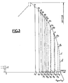
La figure 3 donne à titre d'exemple les diagrammes d'utilisation limite de l'échelle correspondant à la stabilité minimale admise dans les cas d'utilisation suivants :
- a) Extrémité de l'échelle non appuyée ;
poutres 3 rentrées, orientation échelle défavorable (limites indiquées en trait plein) ;- a1) trois hommes plus la plate-forme de sauvetage (portée P1) ;
- a2) trois hommes à l'extrémité, sans plate-forme, ou deux hommes plus plate-forme (portée P4) ;
- a3) deux hommes à l'extrémité, sans plate-forme, ou un homme plus plate-forme (portée P7) ;
- a4) un homme à l'extrémité, sans plate-forme (portée P10) ;
- b) poutres 3 demi-sorties, ces limites deviennent : a'1, a'2, a'3, a'4 (en trait mixte) auxquelles correspondent les portées P2, P5, P8 et P11 ;
- c) poutres 3 sorties ou orientation échelle voisine de l'axe du véhicule, ces limites deviennent a''1, a''2, a''3, a''4 (en trait pointillé) auxquelles correspondent les portées P3, P6, P9, P12 ;
- d) extrémité de l'échelle en appui, deux hommes par plan d'échelle (b, b', b'', selon sortie poutres) auxquelles correspondent les portées P13, P14, P15.
- a) End of the ladder not supported; 3 re-entrant beams, unfavorable scale orientation (limits indicated in solid lines);
- a1) three men plus the rescue platform (range P1);
- a2) three men at the end, without platform, or two men more platform (reach P4);
- a3) two men at the end, without platform, or one man with a platform (litter P7);
- a4) a man at the end, without platform (reach P10);
- b) beams 3 half-outlets, these limits become: a'1, a'2, a'3, a'4 (in phantom) to which the spans P2, P5, P8 and P11 correspond;
- c) 3-outlet beams or scale orientation close to the vehicle axis, these limits become a''1, a''2, a''3, a''4 (in dotted lines) to which the spans P3, P6 correspond , P9, P12;
- d) end of the ladder in support, two men per ladder plane (b, b ', b'', depending on beam exit) to which the spans P13, P14, P15 correspond.
Cette figure 3 symbolise les diagrammes d'utilisation correspondant à trois positions possibles des vérins d'appui, mais une variation continue du diagramme peut être envisagée.This figure 3 symbolizes the usage diagrams corresponding to three possible positions of the support cylinders, but a continuous variation of the diagram can be envisaged.
En fonction de la position des poutres-support des vérins de calage et de l'angle d'orientation de l'échelle par rapport au châssis, une limite d'utilisation de l'échelle, avant tout risque de renversement, est définie expérimentalement pour chaque cas de charge.Depending on the position of the support beams of the timing cylinders and the angle of orientation of the ladder relative to the chassis, a limit of use of the ladder, before any risk of overturning, is defined experimentally for each load case.
Les différentes limites sont mises en mémoire dans le système de contrôle.The different limits are stored in the control system.
Pendant les mouvements de l'échelle, le système de contrôle compare la position de l'échelle à chacune des limites et il allume un voyant qui correspond à la possibilité de charge maximale. Il y a arrêt automatique des mouvements de déploiement, d'abaissement et éventuellement de pivotement lorsque l'échelle équipée de sa plate-forme de sauvetage atteint la limite correspondant au cas de charge a1, a2, et a3, ou lorsque l'échelle sans plate-forme de sauvetage atteint la limite correspondant à a4, ou les limites allant de a'1 à a'4 ou de a''1 à a''4 selon la position des poutres 3.During the movements of the ladder, the control system compares the position of the ladder to each of the limits and lights up an indicator which corresponds to the possibility of maximum load. Automatic deployment, lowering and possibly pivoting movements are stopped when the ladder fitted with its rescue platform reaches the limit corresponding to the load case a1, a2, and a3, or when the ladder without rescue platform reaches the limit corresponding to a4, or the limits going from a'1 to a'4 or from a''1 to a''4 depending on the position of the
La poursuite des mouvements après ces limites pour atteindre les limites b, b', b'' (portées P13, P14, P15) ne peut se faire que si l'opérateur actionne un contacteur « échelle en appui ». Un nouvel arrêt automatique des mouvements de déploiement, d'abaissement et éventuellement de pivotement intervient lorsque les limites b, b' ou b'' sont atteintes.Continuation of movements after these limits to reach limits b, b ', b' '(ranges P13, P14, P15) can only be done if the operator actuates a contactor "ladder in support". A new automatic stop of the deployment, lowering and possibly pivoting movements occurs when the limits b, b 'or b' 'are reached.
A chaque changement de limite de charge, un dispositif sonore est actionné pour attirer l'attention de l'utilisateur.Each time the load limit is changed, an audible device is activated to attract the attention of the user.
Lorsque la plate-forme de sauvetage est utilisée, un capteur signale sa présence.When the rescue platform is used, a sensor signals its presence.
Des interrupteurs permettent de sélectionner les limites : deux hommes plus plate-forme, un homme plus plate-forme. Avant d'atteindre la limite d'utilisation correspondant au cas de charge choisi, un pré-signal intervient ainsi qu'un ralentissement des manoeuvres comme on le verra plus loin.Switches allow you to select the limits: two men plus platform, one man plus platform. Before reaching the usage limit corresponding to the chosen load case, a pre-signal intervenes as well as a slowing down of the maneuvers as will be seen below.
Le principe général de fonctionnement est d'abord ci-après indiqué en se référant au schéma d'ensemble et de la commande à microprocesseur MPU de la figure 4.The general principle of operation is first indicated below with reference to the overall diagram and of the microprocessor control MPU of FIG. 4.
Les informations de position de l'échelle délivrées par les différents capteurs sont lues périodiquement par le microprocesseur et mises en mémoire.The scale position information delivered by the various sensors is read periodically by the microprocessor and stored in memory.
Le microprocesseur traite ces données et compare l'état de l'échelle aux limites d'utilisation stockées en mémoire permanente.The microprocessor processes this data and compares the state of the scale with the limits of use stored in permanent memory.
Les ordres de commande des mouvements (sens et vitesse) donnés par l'opérateur pénètrent dans le microprocesseur; ils sont validés ou modifiés selon le résultat de la comparaison de l'état de l'échelle aux limites d'utilisation puis transmis aux organes de commande de puissance. Simultanément, le microprocesseur génère, s'il y a lieu, les ordres de commande du mouvement automatique de mise à l'horizontale du plancher de la plate-forme.The movement control orders (direction and speed) given by the operator enter the microprocessor; they are validated or modified according to the result of the comparison of the state of the scale to the limits of use and then transmitted to the power control members. Simultaneously, the microprocessor generates, if necessary, the orders for controlling the automatic movement of the horizontal floor of the platform.
S'il advient que l'opérateur demande un mouvement qui devient dangereux pour la stabilité du véhicule, le microprocesseur provoque l'arrêt automatique de ce mouvement lorsque la limite est atteinte, mais après avoir réalisé une décélération progressive du mouvement jusqu'à l'arrêt total et ceci quel que soit l'ordre de commande donné par l'opérateur ainsi qu'on le verra plus loin.If it happens that the operator requests a movement which becomes dangerous for the stability of the vehicle, the microprocessor causes the automatic stop of this movement when the limit is reached, but after having achieved a progressive deceleration of the movement until the total stop and this whatever the command order given by the operator as we will see later.
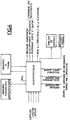
La figure 5 illustre la constitution générale du système électronique à microprocesseur qui comprend : un microprocesseur (MPU) ici le 6802 de MOTOROLA, qui coordonne toutes les fonctions du système et possède une mémoire de travail (RAM) interne de 128 octets.
- ― Deux mémoires programmables (
REPROM 1 et 2) ici les 2716 de MOTOROLA. La totalité du programme est enregistré dans ces mémoires (4K octets avec possibilité d'extension). - ― Une mémoire de travail externe (RAM) ici la 6810 de MOTOROLA. C'est dans cette mémoire que sont stockés les paramètres extérieurs et les résultats des calculs. (128 octets en plus des 128 octets du MPU. Extension possible).
- ― Des interfaces d'adaptation des entrées et sorties à codage d'adresse (
PIA 1 et PIA 2) ici les 6821 de MOTOROLA.
- - Two programmable memories (
REPROM 1 and 2) here the 2716 from MOTOROLA. The entire program is saved in these memories (4K bytes with possibility of extension). - - An external working memory (RAM) here the 6810 from MOTOROLA. It is in this memory that the external parameters and the results of the calculations are stored. (128 bytes in addition to the 128 bytes of the MPU. Extension possible).
- - Adaptation interfaces for address coded inputs and outputs (
PIA 1 and PIA 2) here the 6821 from MOTOROLA.
Tous ces éléments sont reliés ensemble par des BUS usuels.
- ― BUS des DONNEES = ensemble de fils véhiculant les informations d'entrées, sorties ou mémoire.
- ― BUS des ADRESSES = ensemble de fils comportant le codage des emplacements ou destinations des informations véhiculées par le BUS des DONNEES.
- ― BUS de COMMANDE = ensemble de fils par lesquels cheminent les signaux de commande auxiliaires validant les adresses et transferts des données.
- - DATA BUS = set of wires carrying input, output or memory information.
- - ADDRESS BUS = set of wires comprising the coding of the locations or destinations of the information conveyed by the DATA BUS.
- - CONTROL BUS = set of wires through which the auxiliary control signals validate the addresses and data transfers.
De plus, des circuits annexes permettent une adaptation des éléments extérieurs (détecteurs, mesures et commandes pour entrées, contacts, voyants, affichages numériques et commandes de mouvements pour sorties). Ces circuits sont :
- ― Des circuits d'entrées logiques avec opérateurs de puissance (
BUFFERS D'ENTREES - ―
Deux multiplexeurs 1et 2 d'entrées analogiques, ici les IH 6116 de TEKELEC suivis d'un convertisseur Analogique/Numérique. - ― Un circuit de sorties logiques pour voyants de contrôle (sorties S1 à S16).
- ― Huit décodeurs BCD à 7 segments, ici les M 04311B de MITEL, pour affichage numérique de divers paramètres (sorties S25 à S32).
- ― Des convertisseurs Numérique/Analogique pour toutes les sorties de commande proportionnelle des mouvements (S33 à S37).
- ― Un circuit de sorties logiques avec opérateurs de puissance (BUFFER DE SORTIE S17 à S19).
- ― Deux décodeurs servant de démultiplexeurs pour entrées, sorties et circuits d'affichage numérique (ici les décodeurs 74
LS 138 de MOTOROLA).
- - Logic input circuits with power operators (INPUT BUFFERS 1, 2 and 3).
- - Two
multiplexers - - A logic output circuit for indicator lights (outputs S1 to S16).
- - Eight 7-segment BCD decoders, here MITEL's M 04311B, for digital display of various parameters (outputs S25 to S32).
- - Digital / Analog converters for all proportional motion control outputs (S33 to S37).
- - A logic output circuit with power operators (OUTPUT BUFFER S17 to S19).
- - Two decoders serving as demultiplexers for inputs, outputs and digital display circuits (here the 74
LS 138 decoders from MOTOROLA).
La totalité du programme permettant la commande et le contrôle du fonctionnement de l'échelle est enregistré en mémoire REPROM. Sur cette même mémoire sont enregistrées toutes les limites d'utilisation permises suivant les différents cas de figures que l'échelle peut prendre.The entire program allowing the command and control of the operation of the scale is saved in REPROM memory. On this same memory are recorded all the limits of use allowed according to the different scenarios that the scale can take.
Les diverses entrées et sorties ici prises en compte sont notamment :
- ― Entrées logiques : E1 (Alimentation électrique) ; E2 (Pression d'huile des vérins de calage) ; E3 (Echelle sur support échelle) ; E4 (Poutres télescopiques sorties côté gauche) ; ES (Poutres télescopiques sorties côté droit) ; E6 (Poutres télescopiques 1/2 sorties côté gauche) ; E7 (Poutres télescopiques 1/2 sorties côté droit) ; E8 (Réarmement microprocesseur) ; E9 (Plate-forme de sauvetage en bout d'échelle) ; E10 (Utilisation avec deux hommes dans la plate-forme) ; E11 (Utilisation avec un homme dans la plate-forme) ; E12 (Utilisation de l'échelle avec appui) ; E13 (Arrêt d'urgence - coup de poing) ; E14 (Fin de course reploiement) ; E15 (Fin de course déploiement) ; E16 (Marche/arrêt concordance automatique d'échelons) ; E17 (Capteur de concordance d'échelons) ; E18 (Capteur de choc à l'abaissement) ; E19 (Capteur de choc au déploiement) ; E20 (Capteur de choc au pivotement à droite) ; E21 (Capteur de choc au pivotement à gauche) ; E23 (Capteur d'angle de dressage où l'échelle peut heurter la cabine pendant le pivotement) ; E24 (Sécurité dévers maximal) ; E25 (Fin de course abaissement) ; E26 (Fin de course dressage) ; E27 (Début de zone de ralentissement avant fin de course abaissement) ; E28 (Début de zone de ralentissement avant fin de course dressage) ; E29 (Sécurité mise à l'horizontale de la plate-forme à l'abaissement) ; E30 (Sécurité mise à l'horizontale de la plate-forme au dressage) ; E31 (Plate-forme verrouillée en position travail) ; E32 (Plate-forme verrouillée en position route) ; E33 (Commande de retour automatique de l'échelle sur son support) ; E34 (Commande de secours sans sécurité automatique).
- ― Entrées analogiques E41 (Commande dressage/abaissement) ; E42 (Commande déploiement/reploiement) ; E43 (Commande pivotement droite/gauche) ; E44 (Mesure de l'angle de dressage α) ; E45 (Mesure de l'angle de la plate-forme par rapport à l'échelle β) ; E46 (Mesure de l'angle de pivotement θ) ; E47 (Mesure de la longueur développée L) ; E48 (réservée) ; E49 (réservée) ; E50 (Mesure de l'angle de correction de dévers δ) ; E51 (Mesure de surcharge de la structure).
- ― Sorties logiques : S1 (Voyant défaut du système électronique) ; S2 (Voyant dévers trop important) ; S3 (Voyant plate-forme avec trois hommes) ; S4 (Voyant plate-
forme avec 2 hommes) ; S5 (Voyant plate-forme avec un homme) ; S6 (Voyant trois hommes sur l'échelle) ; S7 (Voyant deux hommes sur l'échelle) ; S8 (Voyant un homme sur l'échelle) ; S9 (Voyant échelle en appui) ; S10 (Voyant concordance d'échelons) ; S11 (Voyant demandant le dressage ou le reploiement) ; S12 (Voyant poutres télescopiques sorties ou échelle dans l'axe du châssis) ; S13 (Voyant poutres télescopiques 1/2 sorties) ; S14 (Voyant poutres télescopiques rentrées) ; S15 (Voyant défaut correction dévers) ; S17 (Avertisseur de changement de zone d'utilisation) ; S18 (Avertisseur signalant l'approche ou l'arrêt automatique) ; S19 (Pilotage pression d'huile de la pompe hydraulique). - ― Sorties numériques : S25 (Affichage angle de dressage α) ; S26 (Affichage longueur développée L) ; S27 (Affichage portée) ; S28 (Affichage hauteur) ; S29 (Affichage de la longueur développable avant changement de zone d'utilisation) ; S30 (Affichage de la portée maximale avant changement de zone d'utilisation) ; S31 (Affichage de la hauteur maximale avant changement de zone d'utilisation) ; S32 (Affichage du numéro de capteur défectueux).
- ― Sorties analogiques : S33 (Commande proportionnelle dressage/abaissement) ; S34 (Commande proportionnelle développement/reploiement) ; S35 (Commande proportionnelle pivotement droite/gauche) ; S36 (Commande proportionnelle de mise à l'horizontale de la plate-forme) ; S37 (Commande proportionnelle de correction de dévers).
- - Logic inputs: E1 (Power supply); E2 (Oil pressure of the timing cylinders); E3 (Ladder on ladder support); E4 (Telescopic beams exited on the left side); ES (Telescopic beams exiting right side); E6 (1/2 extension telescopic beams left side); E7 (1/2 extension telescopic beams on right side); E8 (Microprocessor reset); E9 (End of ladder rescue platform); E10 (Use with two men in the platform); E11 (Use with a man in the platform); E12 (Use of ladder with support); E13 (Emergency stop - punch); E14 (Limit switch); E15 (Deployment limit switch); E16 (On / off automatic step matching); E17 (Scale concordance sensor); E18 (Lowering shock sensor); E19 (Deployment shock sensor); E20 (Right pivoting shock sensor); E21 (Left pivoting shock sensor); E23 (Dressing angle sensor where the ladder can hit the cabin during pivoting); E24 (Maximum cant safety); E25 (Lowering limit switch); E26 (Dressage limit switch); E27 (Start of deceleration zone before lowering limit switch); E28 (Start of slowdown zone before end of dressage race); E29 (Safety horizontally lowering the platform); E30 (Safety placed horizontally from the platform to the dressing); E31 (Platform locked in working position); E32 (Platform locked in road position); E33 (Automatic scale return command on its support); E34 (Emergency control without automatic safety).
- - Analog inputs E41 (Dressing / lowering command); E42 (Deployment / deployment control); E43 (Right / left swivel control); E44 (Measurement of the dressing angle α); E45 (Measurement of the angle of the platform with respect to the scale β); E46 (Measurement of the pivot angle θ); E47 (Measurement of the developed length L); E48 (reserved); E49 (reserved); E50 (Measurement of the slope correction angle δ); E51 (Structure overload measurement).
- - Logic outputs: S1 (Electronic system fault indicator); S2 (Overlap indicator too large); S3 (Platform light with three men); S4 (Platform light with 2 men); S5 (Seeing platform with a man); S6 (Seeing three men on the ladder); S7 (Seeing two men on the ladder); S8 (Seeing a man on the ladder); S9 (Scale indicator in support); S10 (Scale agreement indicator); S11 (Indicator requesting training or folding back); S12 (Indicator for telescopic beams extended or ladder in the axis of the chassis); S13 (1/2 exit telescopic beams indicator); S14 (Telescopic beams retracted indicator); S15 (Slope correction fault indicator); S17 (Use area change warning); S18 (Warning signaling automatic approach or stop); S19 (Hydraulic pump oil pressure control).
- - Digital outputs: S25 (Display of dressing angle α); S26 (Extended length display L); S27 (Range display); S28 (Height display); S29 (Display of the developable length before changing the area of use); S30 (Display of the maximum range before changing the area of use); S31 (Display of the maximum height before changing the area of use); S32 (Display of defective sensor number).
- - Analog outputs: S33 (Proportional raising / lowering control); S34 (Proportional development / deployment control); S35 (Proportional control pivoting right / left); S36 (Proportional control for horizontal alignment of the platform); S37 (Proportional tilt correction control).
Le principe de fonctionnement est le suivant :The operating principle is as follows:
Après mise sous tension du dispositif dans son ensemble, le programme prévoit d'initialiser les cases mémoire en RAM.After powering up the device as a whole, the program plans to initialize the memory boxes in RAM.
Le MPU par le BUS des données, en excitant les adresses correspondantes, permet le transfert de REPROM en RAM des paramètres d'initialisation.The MPU via the data BUS, by exciting the corresponding addresses, allows the transfer of REPROM to RAM of the initialization parameters.
Ensuite, le programme prévoit la lecture et le stockage des entrées en RAM. Toutes les entrées logiques E1 à E34 sont présentes sous forme de 1 ou de 0 aux bornes des BUFFERS d'entrée.Then, the program provides for reading and storing the entries in RAM. All digital inputs E1 to E34 are present as 1 or 0 at the terminals of the input BUFFERS.
Le MPU, grâce aux adresses du PIA 1 et du BUFFER 1 d'entrée, lit l'ensemble des entrées E1 à E16 qu'il faut transférer en RAM par le BUS des données et les adresses de mémoire.The MPU, thanks to the addresses of the
De même, pour les entrées E17 à E32 avec le PIA 1 et BUFFER 2 d'entrée et ainsi de suite par séries de 16 entrées.Likewise, for inputs E17 to E32 with the
Toutes les entrées analogiques E41 à E51 sont présentes sous forme de tension aux bornes des multiplexeurs d'entrées analogiques.All analog inputs E41 to E51 are present as a voltage across the terminals of analog input multiplexers.
Le MPU, grâce aux adresses du PIA 1, du multiplexeur 1 et du convertisseur A/N, lit l'entrée E41, convertie en numérique et transfère par le BUS des données et l'adresse de la mémoire, le mot binaire correspondant dans la RAM.The MPU, thanks to the addresses of the
De même, pour chacune des entrées E42 à E48, et pour les entrées E49 à E51 avec les adresses PIA 1, multiplexeur 2 et le convertisseur A/N intermédiaire.Likewise, for each of the inputs E42 to E48, and for the inputs E49 to E51 with the
Lorsque toutes les données extérieures sont en mémoire RAM, le MPU effectue les calculs nécessaires au bon déroulement du programme en allant puiser dans la RAM par le BUS des données et d'adresses les données précédemment stockées.When all the external data is in RAM memory, the MPU performs the calculations necessary for the smooth running of the program by going to draw from RAM by the data BUS and addresses the previously stored data.
Les résultats de ces calculs sont d'une part stockés en RAM par l'intermédiaire du BUS données et de nouvelles adresses et d'autre part affichés sur le tableau de contrôle délimité en trait mixte à la figure 5. Ce transfert vers le panneau d'affichage des voyants logiques : position poutres, cas de charge alerte... se fait par la voie des BUS données et adresses PIA 2 et du Décodeur de sorties, ce qui permet de transmettre jusqu'à 16 informations à la fois (S1 à S15 dans cet exemple).The results of these calculations are firstly stored in RAM via the data BUS and new addresses and secondly displayed on the control panel delimited in dashed line in Figure 5. This transfer to the panel '' display of logic indicators: beam position, alert load case ... is done via data BUS and
L'affichage des paramètres d'angle de dressage, de longueur développée, portée et hauteur se fait par la voie des BUS données et adresses du PIA 2, du Décodeur d'affichage numérique, et d'un décodeur 7 segments pour chaque sortie numérique, c'est-à-dire pour S25 à S32 à la suite.The display of the training angle, developed length, span and height parameters is done via the data buses and addresses of the
Ensuite vient la vérification du fonctionnement de l'échelle (avec ou sans plate-forme) avec prise en compte des informations de commande de vitesse des différents mouvements, des paramètres de sécurité, pour délivrance des ordres de commande de vitesse de déplacement de l'échelle, ceci suivant un ordre de tests défini par l'organigramme que l'on verra plus loin.Then comes the verification of the operation of the ladder (with or without platform) taking into account the speed control information of the different movements, safety parameters, for issuing speed control orders for the movement of the scale, this following an order of tests defined by the flowchart that will be seen below.
Lorsque l'ensemble du programme de l'organigramme a été vu et les ordres de fonctionnement ou d'arrêt donnés, le MPU revient au début du programme.When the entire program in the flowchart has been viewed and the operating or stopping orders given, the MPU returns to the start of the program.
Le MPU, à chaque cycle, fait la lecture de toutes les entrées logiques et analogiques qu'il stocke en RAM aux mêmes adresses que précédemment, les paramètres déjà stockés étant automatiquement effacés.The MPU, on each cycle, reads all the logic and analog inputs that it stores in RAM at the same addresses as before, the parameters already stored being automatically erased.
Ensuite le MPU exécute tous les calculs avec ces nouveaux renseignements et les éléments affichés sont éventuellement mis à jour.Then the MPU performs all the calculations with this new information and the elements displayed are possibly updated.
Dans certains cas, pour éviter un défilement des chiffres par exemple, certaines données ne sont affichées que toutes les 2 secondes par exemple.In some cases, to avoid the digits scrolling for example, certain data are only displayed every 2 seconds for example.
Le MPU boucle le programme en quelques millisecondes. Ce temps est variable suivant le nombre de mouvements exécutés. En tout état de cause, chacun des paramètres de contrôle de l'échelle est lu environ 200 fois par seconde.The MPU completes the program in a few milliseconds. This time is variable depending on the number of movements performed. In any event, each of the scale control parameters is read approximately 200 times per second.
Un auto-contrôle des entrées est inclus dans les programmes ; par exemple, dans les mesures, si deux lectures successives d'une entrée analogique donnent un écart important, la nouvelle valeur n'est pas validée et d'autres mesures sont faites. Si ce défaut persiste, le MPU, par l'affichage du numéro affecté au capteur en défaut, signale cet incident et éventuellement stoppe le fonctionnement normal de l'échelle.Self-checking of the inputs is included in the programs; for example, in measurements, if two successive readings of an analog input give a large deviation, the new value is not validated and other measurements are made. If this fault persists, the MPU, by displaying the number assigned to the faulty sensor, signals this incident and possibly stops the normal operation of the scale.
De même, l'information donnée par certains capteurs logiques est vérifiée en fonction de la mesure d'un paramètre analogique. L'inverse existe également, par exemple, si l'entrée logique E23 est détectée, l'entrée analogique E44 doit obligatoirement donner une valeur d'angle de dressage inférieur à + 6°.Likewise, the information given by certain logic sensors is verified as a function of the measurement of an analog parameter. The reverse also exists, for example, if the logic input E23 is detected, the analog input E44 must obligatorily give a value of dressing angle less than + 6 °.
De plus, chaque fois que le MPU donne un ordre de commande de mouvement, le sens de la variation des mesures analogiques est vérifié, par exemple S34 + 1V = sortie de commande proportionnelle de déploiement. S34 donne donc un signal positif. Le MPU vérifie si la valeur de l'entrée analogique E47 (Mesure de la longueur développée) croit, sinon, comme précédemment, la lecture de l'entrée E47 est effectuée plusieurs fois, et si l'anomalie persiste, il y a affichage du numéro affecté au capteur E47 et arrêt du fonctionnement de l'échelle.In addition, each time the MPU gives a motion command, the direction of variation of the analog measurements is checked, for example S34 + 1V = proportional command output. S34 therefore gives a positive signal. The MPU checks whether the value of the analog input E47 (Measurement of the developed length) believes, if not, as previously, the reading of the input E47 is carried out several times, and if the anomaly persists, there is display of the number assigned to the sensor E47 and the operation of the ladder.
Le système réalise ainsi un auto-contrôle et évite de donner des ordres erronés dans le cas où il reçoit de fausses informations.The system thus performs a self-check and avoids giving erroneous orders in the event that it receives false information.
Le microprocesseur commande également le tableau d'affichage et de signalisation qui renseigne l'utilisateur sur l'état de l'échelle et ses possibilités.The microprocessor also controls the display and signaling panel which informs the user about the state of the scale and its possibilities.
La figure 6 illustre une réalisation du tableau d'affichage. Les informations suivantes sont données à l'opérateur :
- ― Position des vérins de calage par rapport au véhicule :
cases - ― Position de l'échelle : angle de dressage (
case 19, afficheur numérique 20), longueur développée (case 21, afficheur 22), portée (case 23, afficheur 24), hauteur (case 25, afficheur 26) ; - ― Possibilités maximales de l'échelle au même angle de dressage et à la même charge : longueur maximale (
case 27 afficheur 28), portée maximale (case 29, afficheur 30), hauteur maximale (case 31, afficheur 32) ; - ― Possibilités de charge de l'échelle : trois hommes dans la plate-forme (voyant 33) ; deux hommes dans la plate-forme (voyant 34) ; un homme dans la plate-forme (voyant 35) ; trois hommes à l'extrémité de l'échelle (voyant 36) deux hommes à l'extrémité de l'échelle (voyant 37) ; un homme à l'extrémité de l'échelle (voyant 38) ; huit hommes sur l'échelle en appui (voyant 39) ;
- ― Fonction particulière : concordance des échelons des différents éléments de l'échelle (
case 40, voyant 41) ; défaut de fonctionnement du microprocesseur (case 42, voyant 43), nécessité de reployer ou de dresser l'échelle (case 44, voyant 45), mauvais fonctionnement d'un capteur avec affichage du numéro du capteur (case 46, afficheur numérique 47), défaut correction dévers (voyant 48) lescases
- - Position of the timing cylinders relative to the vehicle:
boxes - - Position of the scale: dressing angle (
box 19, digital display 20), developed length (box 21, display 22), range (box 23, display 24), height (box 25, display 26); - - Maximum possibilities of the ladder at the same dressing angle and at the same load: maximum length (
box 27 display 28), maximum range (box 29, display 30), maximum height (box 31, display 32); - - Ladder load possibilities: three men in the platform (light 33); two men in the platform (see 34); a man in the platform (see 35); three men at the end of the scale (light 36) two men at the end of the scale (light 37); a man at the end of the ladder (see 38); eight men on the ladder in support (light 39);
- - Special function: concordance of the steps of the different elements of the scale (
box 40, indicator 41); microprocessor malfunction (box 42, light 43), need to fold or erect the scale (box 44, light 45), malfunction of a sensor with display of the sensor number (box 46, digital display 47) , tilt correction fault (indicator 48)boxes
La figure 7 représente le schéma de principe du circuit hydraulique de commande des mouvements.Figure 7 shows the block diagram of the hydraulic movement control circuit.
Une pompe à débit variable 52 alimente l'ensemble de l'installation à partir d'un réservoir 53. La commande des poutres télescopiques qui supportent les vérins de calage s'effectue par l'intermédiaire des distributeurs 54 et 55 qui alimentent respectivement les vérins 56 des poutres gauches et les vérins 57 des poutres droites. Un distributeur 58 assure la commande de vérins 59 de neutralisation de la suspension élastique du véhicule et des vérins de calage 2. Lorsque les vérins de calage 2 sont en appui au sol, un pressostat 60 enregistre la montée de pression en résultant et il établit la mise sous tension du système électronique de l'échelle par l'entrée E1. Dès lors, la commande des mouvements de l'échelle proprement dite est possible par action sur les électrodistributeurs proportionnels 61, 62, 63 et 64.A
L'électrodistributeur 61 commande le mouvement de déploiement-reploiement par l'intermédiaire du moteur hydraulique 65 qui actionne un treuil. L'électrodistributeur 62 commande le mouvement de dressage-abaissement par l'intermédiaire des vérins 66.The
L'électrodistributeur 63 alimente les vérins de correction de dévers 67 qui provoquent la rotation de la partie 5 de la tourelle.The
L'électrodistributeur 64 commande le mouvement de pivotement à droite ou à gauche par l'intermédiaire du moteur 68.The
Chacun des électrodistributeurs 61, 62, 63, 64 est du type proportionnel c'est-à-dire qu'il délivre un débit proportionnel à la tension de commande des bobines. Un électrodistributeur 51 mis sous tension dès que l'un des électrodistributeurs 61, 62, 63, 64 est également mis sous tension, permet d'envoyer à la pompe 52 l'information de pression maximale nécessaire dans les circuits qui modifie la cylindrée de pompe de façon à ce qu'elle délivre juste le débit nécessaire à l'utilisation, à la pression régnant dans le circuit d'utilisation.Each of the
En l'absence de tension de commande de l'électrodistributeur 51, le débit de la pompe 52 est nul. Ainsi dans le cas où un arrêt d'urgence est demandé par l'opérateur, entrée E13 du microprocesseur, le microprocesseur coupe l'alimentation électrique du distributeur 51, sortie S19 du microprocesseur (pilotage pression d'huile de la pompe à valeur nulle par état 0 de sortie).In the absence of control voltage for the
On a représenté à la figure 8 l'organigramme général des opérations effectuées par le système électronique à microprocesseur.FIG. 8 shows the general flowchart of the operations carried out by the electronic microprocessor system.
Dès que le véhicule est correctement calé, le pressostat 60 effectue la mise sous tension du système électronique qui entre en fonction et effectue les opérations suivantes :
- ― initialisation des mémoires ;
- ― lecture des entrées E1 à E51 et stockage en mémoire travail ;
- ― calcul des paramètres hauteur, portée ;
- ― comparaison de la portée réelle avec les portées limites ;
- ― calcul des valeurs maximales de longueur développée L, portée P, hauteur H possibles avant d'atteindre la prochaine limite à angle de dressage constant ;
- ― vérification si l'échelle est utilisée avec sa plate-forme de travail : si OUI, la vitesse maximale possible de chacun des mouvements Dressage/Abaissement, Déploiement-Reploiement, pivotement droite ou gauche, est réduite car dans ce cas l'échelle est susceptible d'être manoeuvrée avec du personnel dans la plate-forme. Dans le cas contraire, la vitesse maximale est simplement limitée par les composants hydrauliques et mécaniques ;
- ― arrêt d'urgence : si l'arrêt d'urgence (sécurité coup de poing, entrée E13) a été actionné, il y a arrêt de tous les mouvements par retour à zéro des électrodistributeurs 61, 62, 63, 64 et passage de la pompe 52 à débit nul comme précédemment indiqué. Ensuite, le programme se repositionne au début et se réexécute.
- - initialization of memories;
- - reading of inputs E1 to E51 and storage in working memory;
- - calculation of the height and span parameters;
- - comparison of the actual range with the limit ranges;
- - calculation of the maximum values of developed length L, span P, height H possible before reaching the next limit at constant dressing angle;
- - check if the ladder is used with its working platform: if YES, the maximum possible speed of each of the Dressing / Lowering, Deployment-Folding movements, right or left pivoting, is reduced because in this case the scale is likely to be operated with staff in the platform. Otherwise, the maximum speed is simply limited by the hydraulic and mechanical components;
- - emergency stop: if the emergency stop (punch security, input E13) has been activated, all movements are stopped by return to zero of the
solenoid valves pump 52 at zero flow as previously indicated. Then, the program is repositioned at the beginning and re-executed.
Si l'arrêt d'urgence n'est pas demandé, le programme se poursuit.If the emergency stop is not requested, the program continues.
Vérification de la valeur de l'angle de dressage α :Checking the value of the dressing angle α:
S'il est inférieur ou égal à 20° l'influence du dévers sur l'échelle est négligeable et l'échelle doit être à la position correspondant à un dévers nul (δ = 0) afin de permettre éventuellement un retour de l'échelle sur son support route.If it is less than or equal to 20 ° the influence of the superelevation on the scale is negligible and the scale must be at the position corresponding to a zero superelevation (δ = 0) in order to possibly allow a return of the scale on its road support.
Dans le cas où elle ne le serait pas, les mouvements sont arrêtés et l'échelle est remise à la position δ = 0.If it is not, the movements are stopped and the scale is reset to the position δ = 0.
S'il est supérieur, il y a vérification que la correction de dévers est effectuée et que le dévers maximal admis n'est pas atteint (Entrée E24). Dans le cas contraire, il y a arrêt des mouvements pour correction du dévers et retour au début du programme.If it is greater, there is verification that the tilt correction is carried out and that the maximum allowed tilt is not reached (Entry E24). Otherwise, movements are stopped to correct the slope and return to the start of the program.
Le programme comporte ensuite le test de surcharge de l'échelle (Entrée E51).The program then includes the scale overload test (Input E51).
Si OUI, il y a arrêt des mouvements aggravant le cas de charge, que sont le déploiement et l'abaissement, et poursuite du programme par examen des autres mouvements.If YES, there are movements that aggravate the load case, which are deployment and lowering, and continuation of the program by examining the other movements.
Si NON, le programme se poursuit.If NO, the program continues.
Le programme comporte ensuite le contrôle successif des différents mouvements :The program then includes the successive control of the different movements:
Le principe de contrôle des mouvements est le même pour tous les mouvements hormis le reploiement pour lequel il peut se superposer la concordance automatique des échelons.The principle of movement control is the same for all movements except the folding back, for which the automatic concordance of the steps can be superimposed.
Ces mouvements d'abaissement, déploiement, puis dressage sont contrôlés de la façon suivante :These lowering, unfolding, then straightening movements are controlled as follows:
Le mouvement est-il demandé par I'opérateur ? (Entrées E41 à E43)
- NON : maintien ou mise en position d'arrêt de ce mouvement.
- OUI : ce mouvement est-il en fin de course ou engendre-t-il un choc ?
- Si OUI : arrêt du mouvement.
- Si NON : poursuite du programme.
- NO: hold or stop this movement.
- YES: is this movement at the end of the race or does it cause a shock?
- If YES: movement stopped.
- If NO: continuation of the program.
Ce mouvement s'approche-t-il d'un arrêt automatique (zone ralentie) ?
- Si NON : le mouvement est exécuté à la vitesse demandée.
- Si OUI : la vitesse maximale possible en fonction du prochain arrêt est déterminée par le microprocesseur et le mouvement est exécuté à cette vitesse si la vitesse demandée est supérieure ou égale à cette vitesse (voir description plus loin).
- If NO: the movement is executed at the requested speed.
- If YES: the maximum possible speed according to the next stop is determined by the microprocessor and the movement is executed at this speed if the requested speed is greater than or equal to this speed (see description below).
Reploiement : le principe est le même hormis que si le mouvement n'est pas demandé, le système contrôle si la concordance automatique des échelons est demandée :
- Si NON : il y a arrêt du reploiement.
- Si OUI : il y a reploiement lent de l'échelle dans le cas où les échelons ne sont plus en concordance, ou arrêt s'il sont déjà en concordance.
- If NO: the folding is stopped.
- If YES: there is a slow folding of the scale in the case where the steps are no longer in agreement, or stopping if they are already in agreement.
Vérification de l'angle de dressage α :Checking the dressing angle α:
Supérieur ou égal à 70° : la manoeuvre de pivotement est stoppée car par le jeu du dévers du châssis l'angle de dressage peut augmenter. Puis le programme reprend au début.Greater than or equal to 70 °: the pivoting maneuver is stopped because by the backlash of the chassis the angle of dressing can increase. Then the program resumes at the start.
Inférieur à 70° : il y a contrôle des mouvements de pivotement à droite ou à gauche de façon semblable aux autres mouvements puis retour au début du programme.Lower than 70 °: there is control of the swiveling movements to the right or to the left in a similar way to the other movements then return to the beginning of the program.
Les figures 9, 10 et 11 représentent l'organigramme détaillé du calcul des hauteurs et portées, de la mémorisation de la position des poutres support des vérins de stabilisateur, de l'affichage des limites de charges autorisées et de la mise en mémoire de la portée limite correspondant au cas de fonctionnement.Figures 9, 10 and 11 show the detailed flowchart for the calculation of heights and spans, the memorization of the position of the support beams of the stabilizer jacks, the display of the authorized load limits and the storage of the limit range corresponding to the operating case.
Comme indiqué dans la case « calcul » de la figure 9, le microprocesseur après avoir lu tous les paramètres d'entrée, calcule la portée P, la hauteur H, les valeurs maximales de longueur développable L maxi avant arrêt automatique à angle de dressage constant et hauteur H maxi correspondante, la valeur maximale de l'angle de dressage α2 correspondant à la portée maximale pour laquelle il doit y avoir arrêt automatique à longueur développée L constante ; l'angle de dressage αr, la portée Pr et la longueur développée Lr de début de ralentissement des mouvements. Δα correspond à une plage angulaire de ralentissement de l'abaissement avant arrêt automatique, et ΔP et ΔL à deux plages de ralentissement avant arrêt automatique en portée ou longueur développée.As indicated in the “calculation” box of FIG. 9, the microprocessor after having read all the input parameters, calculates the range P, the height H, the maximum values of developable length L maxi before automatic stop at constant angle of dressing and corresponding maximum height H, the maximum value of the dressing angle α2 corresponding to the maximum range for which there must be an automatic stop at constant developed length L; the angle of dressing αr, the range Pr and the developed length Lr at the start of slowing down of the movements. Δα corresponds to an angular range of deceleration of the lowering before automatic stop, and ΔP and ΔL to two ranges of deceleration before automatic stop in range or developed length.
Les différentes valeurs prises en compte sont mémorisées dans des mémoires indiquées dans la case « Calcul » de la figure 9, par la lettre M suivie d'un indice d'identification. Pour ces calculs, le microprocesseur utilise la mémoire M20 dans laquelle est stockée la portée maximale correspondant au cas d'utilisation de l'échelle (fig. 3 et 11).The different values taken into account are stored in memories indicated in the “Calculation” box of FIG. 9, by the letter M followed by an identification index. For these calculations, the microprocessor uses the memory M20 in which the maximum range corresponding to the use of the scale is stored (fig. 3 and 11).
A la mise en marche cette mémoire est initialisée. Les valeurs ainsi calculées sont affichées sur les sorties indiquées dans la case « Affichage ».When switching on this memory is initialized. The values thus calculated are displayed on the outputs indicated in the "Display" box.
Le microprocesseur contrôle ensuite dans quelle position sont les vérins de calage 2 et quelle est l'orientation θ de l'échelle par rapport à l'axe longitudinal du véhicule. Si l'orientation θ de l'échelle ne présente pas un écart supérieur à ± 25° par rapport à l'axe longitudinal du véhicule la portée utile est la portée maximale pour la charge considérée et elle est indépendante de la position des stabilisateurs. Pour des orientations différentes de l'échelle, le microprocesseur mémorise la position des poutres situées du côté où l'échelle est orientée (mémoires M2, M3, M4, fig. 9).The microprocessor then checks in what position the
Le microprocesseur procède ensuite à l'affichage du cas de charge (fig. 10). Il examine si l'échelle est utilisée avec ou sans sa plate-forme (entrée E9) quel est le choix de charge fait par l'utilisateur (1, 2 ou 3 hommes sur la plate-forme, échelle en appui, entrées E10, E11, E12) et il compare, dans le cas de l'échelle utilisée sans plate-forme, la portée réelle de l'échelle stockée dans la mémoire M21, aux portées limites autorisées en fonction de la position des stabilisateurs ; il en déduit la charge maximale possible et procède à l'allumage du voyant correspondant et à l'extinction des autres voyants par les sorties S3 à S9 (voyants 33 à 39).The microprocessor then displays the load case (fig. 10). It examines whether the ladder is used with or without its platform (entry E9) what is the choice of load made by the user (1, 2 or 3 men on the platform, resting ladder, entries E10, E11, E12) and it compares, in the case of the scale used without a platform, the actual range of the scale stored in the memory M21, with the limit ranges authorized as a function of the position of the stabilizers; it deduces the maximum possible load therefrom and proceeds to switch on the corresponding warning light and extinguish the other warning lights by outputs S3 to S9 (warning
Le microprocesseur contrôle ensuite s'il y a concordance des échelons et il fait l'affichage correspondant (voyant 41).The microprocessor then checks if there is a concordance of steps and displays the corresponding display (LED 41).
La séquence suivante est relative à l'émission d'un signal sonore lorsqu'il y a changement de cas de charge ; ainsi un signal sonore de durée 1 seconde est émis lorsque la portée devient égale à P4, P5, P6, P7, P8 ou P9.The following sequence relates to the emission of an audible signal when there is a change of load case; thus an audible signal of
La séquence suivante (fig. 11) affecte à la mémoire M20 la portée maximale (afficheur 30) correspondant au cas d'utilisation de l'échelle et en réalise l'affichage (sortie S30). Le microprocesseur procède ensuite à la limitation des vitesses maximales possibles des mouvements dans le cas où l'échelle est utilisée avec sa plate-forme, comme déjà indiqué (test passant par E9).The following sequence (fig. 11) assigns to memory M20 the maximum range (display 30) corresponding to the use of the scale and displays it (output S30). The microprocessor then proceeds to limit the maximum possible speeds of the movements in the case where the scale is used with its platform, as already indicated (test passing through E9).
Le principe de fonctionnement de commande des mouvements est décrit à l'aide de la figure 12 en prenant comme exemple l'abaissement de l'échelle (avec signaux analogiques sous forme de tension).The operating principle of motion control is described using FIG. 12, taking the example of the lowering of the scale (with analog signals in the form of voltage).
L'opérateur, par l'intermédiaire d'un manipulateur de commande de Dressage/Abaissement, demande l'abaissement de l'échelle et envoie au système électronique une tension proportionnelle à la vitesse demandée. Le système de commande et de contrôle vérifie si le mouvement demandé est exécutable en fonction des divers paramètres de sécurité inscrits au programme et génère, s'il y a compatibilité, le signal de commande (sortie S33) qui sera pris en compte par l'électrodistributeur (62) de commande du mouvement considéré. Les commandes des mouvements, dans l'exemple choisi, se font de la façon suivante :
Comme l'indique l'organigramme de la figure 12, le MPU compare la valeur analogique E41 (stockée avec RAM) avec la valeur - 1 Volt (stockée en REPROM). Deux cas peuvent se produire.
Si le résultat de la comparaison est « pas d'abaissement demandé », le MPU met la sortie S33 à 0 (ou la maintient si elle y était précédemment).If the result of the comparison is "no lowering requested", the MPU sets the output S33 to 0 (or maintains it if it was previously there).
Si le résultat est « abaissement demandé », le MPU vérifie, dans l'ordre du programme les valeurs logiques des entrées E18, E25 et E29 (stockées en RAM). Si l'une d'elles est à 1, la sortie S33 est mise (ou maintenue) à 0.If the result is "lowering requested", the MPU checks, in the order of the program, the logical values of the inputs E18, E25 and E29 (stored in RAM). If one of them is at 1, the output S33 is set (or maintained) at 0.
Ensuite vient la vérification de la position de l'échelle par rapport au châssis en pivotement et en dressage/abaissement pour éviter toute interférence avec la cabine du véhicule (tests A et B).Then comes the verification of the position of the ladder in relation to the pivoting and straightening / lowering chassis to avoid any interference with the vehicle cabin (tests A and B).
Si A et B sont positifs, le MPU met S33 à 0.If A and B are positive, the MPU sets S33 to 0.
Si A est positif et B négatif, le test C est fait.If A is positive and B negative, test C is done.
Si C est positif : la sortie analogique S33 génère un signal proportionnel à l'entrée E41 avec une valeur maximale dégressive en conformité avec une courbe de ralentissement avec arrêt de fin de course, mise en mémoire REPROM et que l'on verra plus loin.If C is positive: the analog output S33 generates a signal proportional to the input E41 with a decreasing maximum value in accordance with a deceleration curve with end of travel stop, REPROM memory storage and which will be seen later.
Si A est négatif ou C, le MPU vérifie l'entrée logique E27 (test D) et le test E.If A is negative or C, the MPU checks logic input E27 (test D) and test E.
Si D ou E est positif la sortie S33 génère comme ci-dessus un signal proportionnel à l'entrée E41 à valeur maximale limitée par ladite courbe de ralentissement avant fin de course.If D or E is positive, the output S33 generates, as above, a signal proportional to the input E41 with maximum value limited by said deceleration curve before end of travel.
Si D et E négatifs, le MPU génère un signal proportionnel à l'entrée E41 sans correction sauf en cas de demande ou de suppression brutale de la commande du mouvement (entrée E41) ou en ce cas le MPU génère le signal de sortie à l'accélération et à la décélération, selon d'autres courbes de pilotage de vitesse mises en mémoire REPROM, ceci pour avoir un plus grand confort de pilotage de l'échelle et éviter des sollicitations mécaniques désagréables de l'échelle.If D and E are negative, the MPU generates a signal proportional to the input E41 without correction except in the event of a sudden request or suppression of the motion control (input E41) or in this case the MPU generates the output signal at l acceleration and deceleration, according to other speed control curves stored in REPROM memory, this in order to have greater comfort in piloting the ladder and to avoid unpleasant mechanical stresses on the ladder.
Dans le cas d'utilisation d'une plate-forme 11 en bout de l'échelle, le MPU qui gère la sortie S33 peut, sans attendre un écart d'horizontalité de la plate-forme, commander simultanément sa mise à l'aplomb en générant un signal proportionnel à S33 sur la sortie S36 : commande proportionnelle de mise à l'horizontale de la plate-forme 11, cette commande proportionnelle pouvant coopérer avec un actionneur non représenté, tel qu'un vérin électrique interposé entre le dernier échelon 10 de l'échelle et la plate-forme pour faire varier l'angle β.In the case of using a
De plus, une boucle de contrôle est incorporée au programme, qui permet, par la mesure de l'angle β de la plate-forme par rapport à l'échelle (E45) de mettre au programme un paramètre de correction permettant de supprimer les écarts dus au système électro-hydro-mécanique de commande de puissance des mouvements de l'échelle.In addition, a control loop is incorporated into the program, which allows, by measuring the angle β of the platform with respect to the scale (E45) to put in the program a correction parameter making it possible to remove the deviations due to the electro-hydro-mechanical system for controlling the power of the ladder's movements.
La commande de dressage est contrôlée et exécutée par le MPU suivant le même principe que la commande d'abaissement ci-dessus, avec bien sûr, des paramètres à contrôler propres à ce mouvement.The training command is controlled and executed by the MPU according to the same principle as the lowering command above, with of course, parameters to control specific to this movement.
La commande des mouvements de déploiement et de reploiement se fait sur le même principe que la commande d'abaissement et de dressage en fonction de l'entrée E42, des tests de sécurité propres à ces mouvements, pour générer un signal proportionnel à la sortie S34 = commande proportionnelle Déploiement/Reploiement.The control of the deployment and folding movements is done on the same principle as the command of lowering and straightening according to the input E42, safety tests specific to these movements, to generate a signal proportional to the output S34 = Deployment / Deployment proportional control.
Pour la commande des mouvements de pivotement à droite ou à gauche, le MPU, comme pour la commande d'abaissement et de dressage, mais en fonction de l'entrée E43 et des tests propres à ces mouvements, génère un signal proportionnel à la sortie S35 = Commande proportionnelle de Pivotement à droite ou à gauche.For the control of pivoting movements to the right or to the left, the MPU, as for the control of lowering and straightening, but depending on the input E43 and tests specific to these movements, generates a signal proportional to the output S35 = Proportional control of Swiveling to the right or to the left.
La figure 13 définit l'organigramme de principe du ralentissement automatique des mouvements de pivotement, abaissement ou déploiement avant arrêt automatique, correspondant à la portée maximale admissible.FIG. 13 defines the principle flow diagram of the automatic slowing down of the pivoting, lowering or deployment movements before automatic stopping, corresponding to the maximum admissible range.
Le microprocesseur reçoit les ordres de mouvement de l'opérateur. Si la portée P est supérieure ou égale à la portée maximale admissible Pa, le microprocesseur ne commande pas le mouvement.The microprocessor receives the operator's movement orders. If the range P is greater than or equal to the maximum admissible range Pa, the microprocessor does not control the movement.
Si la portée P est inférieure à la portée maximale admissible Pa, le microprocesseur compare la portée P à la portée Pr correspondant au début de la zone où le mouvement doit être ralenti afin d'atteindre le point d'arrêt automatique à vitesse nulle.If the range P is less than the maximum admissible range Pa, the microprocessor compares the range P with the range Pr corresponding to the start of the zone where the movement must be slowed down in order to reach the automatic stopping point at zero speed.
La figure 14 illustre le diagramme de la vitesse du mouvement en fonction de l'espace parcouru. Dans la zone A correspondant à une portée P inférieure ou égale à Pr, la vitesse du mouvement est celle demandée par l'opérateur et elle peut aller jusqu'à la vitesse maximale Vm permise par les systèmes de commande.Figure 14 illustrates the diagram of the speed of movement as a function of the space traveled. In the zone A corresponding to a range P less than or equal to Pr, the speed of the movement is that requested by the operator and it can go up to the maximum speed Vm allowed by the control systems.
Dans la zone B correspondant à une portée P supérieure à Pr et inférieure à Pa, le microprocesseur impose une vitesse maximale définie par la limite C qui joint le point de début de ralentissement où la vitesse peut être maximale au point de fin de ralentissement où la vitesse doit être nulle.In zone B corresponding to a range P greater than Pr and less than Pa, the microprocessor imposes a maximum speed defined by the limit C which joins the point of start of deceleration where the speed can be maximum at the point of end of deceleration where the speed must be zero.
Dans la zone B le microprocesseur commande le mouvement à la vitesse demandée par l'opérateur aussi longtemps que celle-ci est inférieure à la vitesse limite définie par la courbe C, puis à la vitesse correspondant à cette courbe C lorsque la vitesse demandée par l'opérateur devient supérieure à cette dernière. Un tel système de ralentissement de mouvement n'est efficacement réalisable que grâce à l'utilisation d'un microprocesseur car les zones de ralentissement de chaque mouvement sont fonction du grand nombre de paramètres dont dépend la portée limite Pa et elles doivent être recalculées constamment en cours de mouvement, ainsi qu'on la vu, les divers mouvements de l'échelle pouvant être simultanés et influençant la portée limite Pa. Le microprocesseur limite ainsi dans tous les cas les effets dynamiques néfastes et notamment tout balancement de l'échelle indésirable.In zone B the microprocessor controls the movement at the speed requested by the operator as long as this is lower than the limit speed defined by curve C, then at the speed corresponding to this curve C when the speed requested by l operator becomes superior to the latter. Such a movement slowdown system is only effectively achievable thanks to the use of a microprocessor because the slowdown zones of each movement are a function of the large number of parameters on which the limit range Pa depends and they must be constantly recalculated in course of movement, as we have seen, the various movements of the scale being able to be simultaneous and influencing the limit range Pa. The microprocessor thus limits in all cases the harmful dynamic effects and in particular any swinging of the undesirable scale.
Plus particulièrement le ralentissement des divers mouvements peut être contrôlé de la manière suivante par le microprocesseur.More particularly, the slowing down of the various movements can be controlled in the following manner by the microprocessor.
Lorsque la portée P est comprise entre les portées Pr et Pa, le microprocesseur calcule la vitesse maximale admissible pour chaque mouvement correspondant à un ralentissement progressif. Pour cela, chaque mouvement est considéré comme s'il était exécuté seul, cela n'étant possible que grâce à la très grande rapidité de calcul du microprocesseur.When the range P is between the ranges Pr and Pa, the microprocessor calculates the maximum admissible speed for each movement corresponding to a progressive deceleration. For this, each movement is considered as if it were executed alone, this being possible only thanks to the very high calculation speed of the microprocessor.
A l'instant t l'extrémité de l'échelle est en N à une distance x de la zone du point d'arrêt automatique. L'espace L étant partagé en n1 pas de décélération, la Vitesse maximale de développement compatible avec le ralentissement progressif est donnée par la relation suivante :![]()
![]()
Le microprocesseur qui possède en mémoire la relation vitesse-ordre de commande S34 du mouvement de développement, détermine l'ordre de commande S34m maximal qui correspond à la vitesse maximale VLm (N) admissible.The microprocessor which has in memory the speed-command relation S34 of the development movement, determines the maximum command command S34 m which corresponds to the maximum admissible speed V Lm (N).
de la même façon que pour le développement on a :![]()
![]()
Le microprocesseur qui possède en mémoire la relation vitesse-ordre de commande S33 du mouvement d'abaissement détermine l'ordre de commande S33m maximal qui correspond à la vitesse maximale Vαm (R) admissible.The microprocessor which has in memory the speed-command relationship S33 of the lowering movement determines the maximum command order S33 m which corresponds to the maximum admissible speed Vα m (R).
Pendant le pivotement, la portée Pa correspondant à l'arrêt automatique peut changer, par exemple lorsque l'échelle s'écarte de l'axe longitudinal du véhicule et que les poutres des vérins sont rentrées ou demi-sorties. Dans ce cas, si l'extrémité T de l'échelle correspond à une portée supérieure à la valeur admissible pour ![]()
![]()
![]()
![]()
![]()
![]()
Le microprocesseur qui possède en mémoire la relation vitesse-ordre de commande S35 du mouvement de pivotement, détermine l'ordre de commande S35m maximal qui correspond à la vitesse maximale Vθm (T) admissible.The microprocessor which has in memory the speed-command relation S35 of the pivoting movement, determines the maximum command command S35 m which corresponds to the maximum admissible speed V θm (T).
En variante, il est possible de réaliser une loi de portée en fonction de l'angle de pivotement telle que la trajectoire de l'extrémité de l'échelle projetée sur le plan horizontal soit une parallèle à l'axe longitudinal du véhicule dans le secteur où il peut y avoir risque de basculement, cette loi étant illustrée par la courbe (C) représentée sur la figure 19.As a variant, it is possible to carry out a range law as a function of the pivoting angle such that the trajectory of the end of the scale projected on the horizontal plane is parallel to the longitudinal axis of the vehicle in the sector where there may be a risk of tilting, this law being illustrated by the curve (C) represented in FIG. 19.
La figure 21 définit l'organigramme de principe de la mise à l'horizontale de la plate-forme de travail 11.FIG. 21 defines the principle flow diagram for the horizontal positioning of the working
Pour que la plate-forme de travail reste horizontale, le microprocesseur commande simultanément le mouvement angulaire de la plate-forme et le dressage ou l'abaissement de l'échelle à la même vitesse. Pour éviter les risques de dérive, des capteurs de types connus tels que potentiomètres ou codeurs angulaires mesurent l'angle de dressage α et l'angle β du plancher de la plate-forme par rapport à l'échelle.To keep the work platform horizontal, the microprocessor simultaneously controls the angular movement of the platform and the raising or lowering of the ladder at the same speed. To avoid the risks of drift, sensors of known types such as potentiometers or angular encoders measure the angle of dressing α and the angle β of the platform floor relative to the scale.
En cas d'écart, le microprocesseur calcule la vitesse nécessaire pour suivre le mouvement de dressage ou abaissement et pour supprimer l'écart de position au bout d'un temps défini, par exemple 5 secondes.In the event of a deviation, the microprocessor calculates the speed necessary to follow the raising or lowering movement and to remove the position deviation after a defined time, for example 5 seconds.
Ce dispositif qui réalise le mouvement angulaire simultané de la plate-forme 11 et de l'échelle permet d'avoir une mise à l'horizontale de la plate-forme précise et sans à-coup, ce qui améliore le confort des passagers.This device which performs the simultaneous angular movement of the
Lorsque l'opérateur demande un mouvement qui devient dangereux pour la stabilité du véhicule, le microprocesseur provoque ainsi qu'exposé l'arrêt automatique de ce mouvement lorsque la limite est atteinte, après avoir réalisé la décélération progressive de ce mouvement.When the operator requests a movement which becomes dangerous for the stability of the vehicle, the microprocessor thus causes, as explained, the automatic stopping of this movement when the limit is reached, after having achieved the progressive deceleration of this movement.
L'arrêt du mouvement étant effectif, le voyant demandant le dressage ou le reploiement (S11 - voyant 45, fig. 6) s'allume.The movement being stopped, the light requesting training or folding back (S11 -
L'opérateur, pouvant être dans un contexte de panique, peut ne pas réagir immédiatement et se demander pourquoi l'échelle n'est plus commandée. C'est alors que l'émission d'un message parlé prend toute sa valeur et est ici assurée à partir du microprocesseur selon le schéma de la figure 22.The operator, who may be in a context of panic, may not react immediately and wonder why the ladder is no longer ordered. It is then that the transmission of a spoken message takes on its full value and is here provided from the microprocessor according to the diagram in FIG. 22.
Le microprocesseur à ce moment, envoie par les BUS, les informations nécessaires à la diffusion du message correspondant au cas de figure ayant provoqué l'arrêt automatique. Les circuits mémoire 69 et synthétiseur de paroles 70 fabriquent la phrase à diffuser qui, après amplification en 71 est transmise à un haut-parleur 72 placé près de l'opérateur d'échelle agissant dans le véhicule. Un deuxième poste d'écoute 73 peut être mis au poste de commande d'échelle situé dans la plate-forme 11 pour informer un opérateur agissant à partir de la plate-forme.The microprocessor at this time, sends by BUS, the information necessary for the dissemination of the message corresponding to the scenario that caused the automatic shutdown. The
L'utilisation d'un microprocesseur permet par ailleurs une plus grande facilité d'adaptation à des contraintes particulières. Ainsi, lorsque l'échelle ou le bras élévateur est monté sur différents types de châssis-cabine, les limites de fonctionnement changent et il suffit de modifier les valeurs mises en mémoire. De même, si des modifications ou des options sont demandées dans le système de sécurité, il suffit d'adjoindre éventuellement des capteurs supplémentaires et de modifier le programme. C'est dire que de nombreuses variantes peuvent être aisément adaptées tout en restant dans le cadre de l'invention.The use of a microprocessor also allows greater ease of adaptation to particular constraints. Thus, when the ladder or the lifting arm is mounted on different types of chassis-cabin, the operating limits change and it suffices to modify the values stored in memory. Likewise, if modifications or options are requested in the security system, it suffices to add additional sensors if necessary and to modify the program. This means that many variants can be easily adapted while remaining within the scope of the invention.
Claims (8)
- Control device for a rotatable, extendable ladder, or similar lifting arm, provided with an articulated platform suitable for transporting one or more persons, comprising at least a control for raising and lowering, a control for extension and retraction and a control for pivoting, with manual means for selecting the movements desired, and actuators for raising and lowering, for extension and retraction and for rotation, said selecting means being suitable for supplying electrical signals representative of the control direction and the desired speed of execution of the movements desired, characterised by the fact that it comprises a control signal reading microprocessor receiving said electrical signals, said microprocessor comprising in memory: the maximum reaches, not to be exceeded, according to different selectable and pre-determined parameters for operation of the ladder, including pre-determined loading options and pre-determined ladder orientations; a cyclic sequence of calculation of the actual reach from data supplied by sensors for measuring the angle of raising and the length extended; a cyclic sequence of comparison of the calculated actual reach with the maximum reach corresponding to pre-defined operating conditions and authorising or not the movement requested, by the fact that said microprocessor comprises in its memory a law for deceleration, at least for the lowering and extending movements in terminal zones pre-determined for the course of these movements, corresponding to a certain approach to the maximum pre-determined operating reach corresponding to the circumstances in which the ladder is being operated, taking into account the load selection made by the user, said terminal zones being limited by said pre-determined maximum operating reach and being continuously recalculated by the microprocessor during movement, and by the fact that the microprocessor comprises in its memory a cyclic sequence of comparison, in this approach, of the control speed indicated to the speed derived from said rule for each movement concerned, intended for applying said rule when the indicated control speed is excessive, by supplying to the outputs of the microprocessor controlling these movements signals representing the indicated control speed, or automatically modified according to said rule, to obtain the maximum pre-determined reach at zero speed, said outputs being connected to electrical proportioning control means for activating actuators for the movements concerned.
- The control device according to claim 1, characterised in that the microprocessor contains in its memory a law of acceleration for the start up and a law of deceleration for stopping, imposed in response to any signal of voluntary command for starting up or stopping for each movement considered.
- The control device according to claim 2, characterised in that it includes sensors of the maximum allowable positions for the movements considered, imposing the law of deceleration before stopping.
- The control device according to any of the preceding claims, characterised in that to the microprocessor is associated a memory of instructions selectively activated in response to diverse border-line cases to stop automatically the movements considered and connect to a voice synthesizer to emit spoken messages of instructions for the information of the operator.
- The control device according to any of the preceding claims, characterised in that it includes, connected to the microprocessor, display circuits for the determined limiting values of the maximal reach and corresponding developed length and angle of raising and lowering, for the actual values of extended length and vertical angle measured by sensors, and for the corresponding calculated reach.
- The control device according to any of the preceding claims, characterised in that it includes, connected to the microprocessor, an audible warning system of temporary activation for the pre-determined changes of the limiting maximal reach, corresponding to changes of the case of possible load appearing on the display equally connected to the microprocessor.
- The control device according to any of the preceding claims, characterised in that it includes, connected to the microprocessor, an audible warning system of temporary activation for the entry into use of the said law of automatic deceleration to forewarn of an imposed slowing before an automatic full stop.
- The control device according to any of the preceding claims, for a ladder or lifting arm including a platform at its articulated end and an activator to horizontal position of the platform, characterised in that it includes a sensor for the measurement of the angle of the platform relative to the ladder or arm and that the microprocessor contains in its memory a sequence of cyclic comparisons of values supplied by the sensor of the measure of platform angle, in order to apply to an output of the microprocessor connected to an instrument of electric control proportional to the activator of horizontal position, a signal derived from the signal of control of the speed of raising or lowering in the absence of difference of comparison, or a corrected signal according to the difference of comparison by a sequence of cyclic correction provided within the microprocessor.
Priority Applications (1)
| Application Number | Priority Date | Filing Date | Title |
|---|---|---|---|
| AT82101486T ATE11950T1 (en) | 1981-03-05 | 1982-02-26 | CONTROL UNIT WITH A MICROPROCESSOR FOR A ROTATING, DEPLOYABLE LADDER OR SIMILAR LIFTING ARM. |
Applications Claiming Priority (2)
| Application Number | Priority Date | Filing Date | Title |
|---|---|---|---|
| FR8104449A FR2501390A1 (en) | 1981-03-05 | 1981-03-05 | MICROPROCESSOR CONTROL DEVICE FOR DEPLOYABLE ORIENTABLE SCALE OR SIMILAR ELEVATOR ARM |
| FR8104449 | 1981-03-05 |
Publications (3)
| Publication Number | Publication Date |
|---|---|
| EP0059901A1 EP0059901A1 (en) | 1982-09-15 |
| EP0059901B1 EP0059901B1 (en) | 1985-02-20 |
| EP0059901B2 true EP0059901B2 (en) | 1996-09-04 |
Family
ID=9255906
Family Applications (1)
| Application Number | Title | Priority Date | Filing Date |
|---|---|---|---|
| EP82101486A Expired - Lifetime EP0059901B2 (en) | 1981-03-05 | 1982-02-26 | Microprocessor-controlled device for a rotatable, extendable ladder or similar lifting arm |
Country Status (6)
| Country | Link |
|---|---|
| EP (1) | EP0059901B2 (en) |
| AT (1) | ATE11950T1 (en) |
| DE (1) | DE3262363D1 (en) |
| ES (1) | ES8305510A1 (en) |
| FR (1) | FR2501390A1 (en) |
| MA (1) | MA19406A1 (en) |
Cited By (2)
| Publication number | Priority date | Publication date | Assignee | Title |
|---|---|---|---|---|
| WO2006000645A1 (en) * | 2004-06-29 | 2006-01-05 | Bronto Skylift Oy Ab | Ladder arrangement, person lifter and method of using a person lifter |
| US11447379B2 (en) | 2018-10-09 | 2022-09-20 | J.C. Bamford Excavators Limited | Machine, controller and control method |
Families Citing this family (16)
| Publication number | Priority date | Publication date | Assignee | Title |
|---|---|---|---|---|
| GB8406094D0 (en) * | 1984-03-08 | 1984-04-11 | Merryweather & Sons | Control system |
| EP0196888B1 (en) * | 1985-03-28 | 1990-10-03 | Kabushiki Kaisha Hikoma Seisakusho | Lifting apparatus |
| FR2583898B1 (en) * | 1985-06-21 | 1988-05-20 | Camiva Sa | METHOD FOR CONTROLLING A LADDER ON A VEHICLE |
| ES2050748T3 (en) * | 1989-03-16 | 1994-06-01 | Ppm Sa | PROCEDURE AND DEVICE FOR THE CONTROL OF THE CRANE FUNCTIONS OF A MOBILE CRANE WITH TELESCOPIC BOOM. |
| JP2564060B2 (en) * | 1991-10-24 | 1996-12-18 | 株式会社神戸製鋼所 | Safety equipment for construction machinery |
| DE4223695C2 (en) * | 1992-07-21 | 1994-12-08 | Weber Anlagenbau Gmbh & Co Kg | Control for pivoting a boom that is variable in its effective length |
| DE29519871U1 (en) * | 1995-12-14 | 1996-03-21 | Liebherr-Werk Ehingen Gmbh, 89584 Ehingen | Crane vehicle |
| DE29519928U1 (en) * | 1995-12-15 | 1996-04-04 | Liebherr-Werk Ehingen Gmbh, 89584 Ehingen | Crane vehicle with an overload protection device |
| FR2750972B1 (en) * | 1996-07-12 | 1998-10-02 | Fdi Sambron | HANDLING TROLLEY PROVIDED WITH A SECURITY SYSTEM TO AVOID ITS ACCIDENTAL TIP |
| GB2471134B (en) | 2009-06-19 | 2012-10-10 | Bamford Excavators Ltd | Speed sensitive longitudinal load moment control of a working machine |
| CN102536103B (en) * | 2011-12-30 | 2013-12-04 | 长沙中联消防机械有限公司 | Method, device and system for controlling arm support recycling and vehicle for arm support recycling |
| CN103100150B (en) * | 2013-02-22 | 2015-04-08 | 王永庆 | High-altitude rescue device and assembly method thereof |
| EP3431436B1 (en) | 2017-07-17 | 2020-04-15 | Manitou Bf | Process for the control of a handling machine, and corresponding handling machine |
| EP3431435B1 (en) | 2017-07-17 | 2020-04-22 | Manitou Bf | Control of a handling machine |
| IT201800004135A1 (en) | 2018-03-30 | 2019-09-30 | Manitou Italia Srl | Articulated self-propelled operating machine. |
| CN113880015A (en) * | 2021-09-02 | 2022-01-04 | 潍柴动力股份有限公司 | Aerial work platform control method and device, electronic equipment and storage medium |
Family Cites Families (4)
| Publication number | Priority date | Publication date | Assignee | Title |
|---|---|---|---|---|
| US4216868A (en) * | 1978-08-04 | 1980-08-12 | Eaton Corporation | Optical digital sensor for crane operating aid |
| DE2836337C2 (en) * | 1978-08-19 | 1987-01-22 | Iveco Magirus AG, 7900 Ulm | Device for switching and monitoring the movements of a motor-driven turntable ladder or similar height-adjustable work equipment |
| JPS55129085A (en) * | 1979-03-26 | 1980-10-06 | Janome Sewing Machine Co Ltd | Electronic sewing machine |
| GB2050294B (en) * | 1979-05-18 | 1983-04-07 | Coles Cranes Ltd | Safe load indicator |
-
1981
- 1981-03-05 FR FR8104449A patent/FR2501390A1/en active Granted
-
1982
- 1982-02-26 AT AT82101486T patent/ATE11950T1/en not_active IP Right Cessation
- 1982-02-26 DE DE8282101486T patent/DE3262363D1/en not_active Expired
- 1982-02-26 EP EP82101486A patent/EP0059901B2/en not_active Expired - Lifetime
- 1982-03-04 ES ES510139A patent/ES8305510A1/en not_active Expired
- 1982-03-05 MA MA19611A patent/MA19406A1/en unknown
Cited By (2)
| Publication number | Priority date | Publication date | Assignee | Title |
|---|---|---|---|---|
| WO2006000645A1 (en) * | 2004-06-29 | 2006-01-05 | Bronto Skylift Oy Ab | Ladder arrangement, person lifter and method of using a person lifter |
| US11447379B2 (en) | 2018-10-09 | 2022-09-20 | J.C. Bamford Excavators Limited | Machine, controller and control method |
Also Published As
| Publication number | Publication date |
|---|---|
| EP0059901B1 (en) | 1985-02-20 |
| EP0059901A1 (en) | 1982-09-15 |
| ES510139A0 (en) | 1983-04-01 |
| ATE11950T1 (en) | 1985-03-15 |
| ES8305510A1 (en) | 1983-04-01 |
| FR2501390B1 (en) | 1984-06-22 |
| FR2501390A1 (en) | 1982-09-10 |
| DE3262363D1 (en) | 1985-03-28 |
| MA19406A1 (en) | 1982-10-01 |
Similar Documents
| Publication | Publication Date | Title |
|---|---|---|
| EP0059901B2 (en) | Microprocessor-controlled device for a rotatable, extendable ladder or similar lifting arm | |
| US4942529A (en) | Lift truck control systems | |
| EP0802469B1 (en) | Device for aircraft ground collision avoidance with turn prediction | |
| CA2472290C (en) | Deceleration control assistance system for taxying aircraft | |
| EP1602994B1 (en) | Method and system for providing security for an aircraft during low altitude flight | |
| WO2007093698A1 (en) | Method and system for predicting the possibility of complete stoppage of an aircraft on a landing runway | |
| EP1907910A2 (en) | Method and device for making secure low altitude automatic flight of an aircraft | |
| JP2020052070A (en) | Head-up display device | |
| CA2503032C (en) | Process and device for securing a low-altitude flight by an aircraft | |
| CA2640321A1 (en) | Method and device for detecting a lateral dissymmetry of an aircraft | |
| WO2022200040A1 (en) | Collision avoidance system for a mobile crane on a work site | |
| FR2628375A1 (en) | METHOD AND INSTALLATION FOR THE AUTOMATIC CONTROL OF A GUIDED VEHICLE | |
| EP0687626A1 (en) | Observation system utilizing a remote controlled aircraft | |
| EP3912950B1 (en) | System for managing working modes of a mobile crane on a site | |
| FR3053313A1 (en) | AUTOMATIC LOAD POSITIONING SYSTEM FOR A HELICOPTER EQUIPPED WITH AN OUTSIDE WINCH | |
| CA2502503C (en) | Pilot display for an aircraft | |
| KR20220030605A (en) | Safety Management System for Tower Crane | |
| CA2502617A1 (en) | Process and device for securing a low-altitude flight by an aircraft | |
| EP0252841A1 (en) | Automatic control device of the retardation of the rotation of a boom and/or counter-boom of hoisting machines | |
| JP3649781B2 (en) | Tower crane safety equipment | |
| EP0392938A1 (en) | Safety braking device for a funicular vehicle | |
| EP1249813B1 (en) | Device for monitoring the surround surveillance system of a plane | |
| FR2502772A1 (en) | Ground coordinate position measuring system for hovering helicopter - has weighted cable connected to winch via spring balance and rotary forks to determine ground coordinates | |
| JPH011654A (en) | Ropeway gondola rolling display device | |
| FR3103975A1 (en) | BOX FOR THE ROBOTIZATION OF A HANDLING MACHINE |
Legal Events
| Date | Code | Title | Description |
|---|---|---|---|
| PUAI | Public reference made under article 153(3) epc to a published international application that has entered the european phase |
Free format text: ORIGINAL CODE: 0009012 |
|
| AK | Designated contracting states |
Designated state(s): AT BE CH DE GB IT NL SE |
|
| 17P | Request for examination filed |
Effective date: 19830315 |
|
| ITF | It: translation for a ep patent filed | ||
| GRAA | (expected) grant |
Free format text: ORIGINAL CODE: 0009210 |
|
| AK | Designated contracting states |
Designated state(s): AT BE CH DE GB IT LI NL SE |
|
| REF | Corresponds to: |
Ref document number: 11950 Country of ref document: AT Date of ref document: 19850315 Kind code of ref document: T |
|
| REF | Corresponds to: |
Ref document number: 3262363 Country of ref document: DE Date of ref document: 19850328 |
|
| PLBI | Opposition filed |
Free format text: ORIGINAL CODE: 0009260 |
|
| PLBI | Opposition filed |
Free format text: ORIGINAL CODE: 0009260 |
|
| 26 | Opposition filed |
Opponent name: IVECO MAGIRUS AG Effective date: 19851102 |
|
| 26 | Opposition filed |
Opponent name: DR.-ING. LUDWIG PIETZSCH GMBH & CO. Effective date: 19851118 |
|
| NLR1 | Nl: opposition has been filed with the epo |
Opponent name: IVECO MAGIRUS AG |
|
| NLR1 | Nl: opposition has been filed with the epo |
Opponent name: DR.-ING. LUDWIG PIETZSCH GMBH & CO. |
|
| PLAB | Opposition data, opponent's data or that of the opponent's representative modified |
Free format text: ORIGINAL CODE: 0009299OPPO |
|
| R26 | Opposition filed (corrected) |
Opponent name: IVECO MAGIRUS AG * 851118 DR.-ING. LUDWIG PIETZSCH Effective date: 19851102 |
|
| ITTA | It: last paid annual fee | ||
| PLAB | Opposition data, opponent's data or that of the opponent's representative modified |
Free format text: ORIGINAL CODE: 0009299OPPO |
|
| R26 | Opposition filed (corrected) |
Opponent name: IVECO MAGIRUS AG * 851118 DR.-ING. LUDWIG PIETZSCH Effective date: 19851102 |
|
| PLAB | Opposition data, opponent's data or that of the opponent's representative modified |
Free format text: ORIGINAL CODE: 0009299OPPO |
|
| R26 | Opposition filed (corrected) |
Opponent name: IVECO MAGIRUS AG * 851118 DR.-ING. LUDWIG PIETZSCH Effective date: 19851102 |
|
| EAL | Se: european patent in force in sweden |
Ref document number: 82101486.7 |
|
| PLAW | Interlocutory decision in opposition |
Free format text: ORIGINAL CODE: EPIDOS IDOP |
|
| PLAW | Interlocutory decision in opposition |
Free format text: ORIGINAL CODE: EPIDOS IDOP |
|
| PUAH | Patent maintained in amended form |
Free format text: ORIGINAL CODE: 0009272 |
|
| STAA | Information on the status of an ep patent application or granted ep patent |
Free format text: STATUS: PATENT MAINTAINED AS AMENDED |
|
| REG | Reference to a national code |
Ref country code: CH Ref legal event code: NV Representative=s name: AMMANN PATENTANWAELTE AG BERN |
|
| 27A | Patent maintained in amended form |
Effective date: 19960904 |
|
| AK | Designated contracting states |
Kind code of ref document: B2 Designated state(s): AT BE CH DE GB IT LI NL SE |
|
| REG | Reference to a national code |
Ref country code: CH Ref legal event code: AEN Free format text: MAINTIEN DU BREVET DONT L'ETENDUE A ETE MODIFIEE |
|
| NLR2 | Nl: decision of opposition | ||
| ITF | It: translation for a ep patent filed | ||
| PGFP | Annual fee paid to national office [announced via postgrant information from national office to epo] |
Ref country code: GB Payment date: 19970113 Year of fee payment: 16 |
|
| PGFP | Annual fee paid to national office [announced via postgrant information from national office to epo] |
Ref country code: BE Payment date: 19970116 Year of fee payment: 16 |
|
| PGFP | Annual fee paid to national office [announced via postgrant information from national office to epo] |
Ref country code: SE Payment date: 19970123 Year of fee payment: 16 |
|
| PGFP | Annual fee paid to national office [announced via postgrant information from national office to epo] |
Ref country code: DE Payment date: 19970124 Year of fee payment: 16 |
|
| PGFP | Annual fee paid to national office [announced via postgrant information from national office to epo] |
Ref country code: AT Payment date: 19970128 Year of fee payment: 16 |
|
| PGFP | Annual fee paid to national office [announced via postgrant information from national office to epo] |
Ref country code: NL Payment date: 19970130 Year of fee payment: 16 |
|
| PGFP | Annual fee paid to national office [announced via postgrant information from national office to epo] |
Ref country code: CH Payment date: 19970131 Year of fee payment: 16 |
|
| NLR3 | Nl: receipt of modified translations in the netherlands language after an opposition procedure | ||
| PG25 | Lapsed in a contracting state [announced via postgrant information from national office to epo] |
Ref country code: GB Free format text: LAPSE BECAUSE OF NON-PAYMENT OF DUE FEES Effective date: 19980226 Ref country code: AT Free format text: LAPSE BECAUSE OF NON-PAYMENT OF DUE FEES Effective date: 19980226 |
|
| PG25 | Lapsed in a contracting state [announced via postgrant information from national office to epo] |
Ref country code: SE Free format text: LAPSE BECAUSE OF NON-PAYMENT OF DUE FEES Effective date: 19980227 |
|
| PG25 | Lapsed in a contracting state [announced via postgrant information from national office to epo] |
Ref country code: LI Free format text: LAPSE BECAUSE OF NON-PAYMENT OF DUE FEES Effective date: 19980228 Ref country code: CH Free format text: LAPSE BECAUSE OF NON-PAYMENT OF DUE FEES Effective date: 19980228 Ref country code: BE Free format text: LAPSE BECAUSE OF NON-PAYMENT OF DUE FEES Effective date: 19980228 |
|
| BERE | Be: lapsed |
Owner name: CAMIVA Effective date: 19980228 |
|
| PG25 | Lapsed in a contracting state [announced via postgrant information from national office to epo] |
Ref country code: NL Free format text: LAPSE BECAUSE OF NON-PAYMENT OF DUE FEES Effective date: 19980901 |
|
| GBPC | Gb: european patent ceased through non-payment of renewal fee |
Effective date: 19980226 |
|
| REG | Reference to a national code |
Ref country code: CH Ref legal event code: PL |
|
| EUG | Se: european patent has lapsed |
Ref document number: 82101486.7 |
|
| NLV4 | Nl: lapsed or anulled due to non-payment of the annual fee |
Effective date: 19980901 |
|
| PG25 | Lapsed in a contracting state [announced via postgrant information from national office to epo] |
Ref country code: DE Free format text: LAPSE BECAUSE OF NON-PAYMENT OF DUE FEES Effective date: 19981103 |
|
| APAH | Appeal reference modified |
Free format text: ORIGINAL CODE: EPIDOSCREFNO |