EP0059913A1 - Mehrteiliges Zaunsystem - Google Patents
Mehrteiliges Zaunsystem Download PDFInfo
- Publication number
- EP0059913A1 EP0059913A1 EP82101544A EP82101544A EP0059913A1 EP 0059913 A1 EP0059913 A1 EP 0059913A1 EP 82101544 A EP82101544 A EP 82101544A EP 82101544 A EP82101544 A EP 82101544A EP 0059913 A1 EP0059913 A1 EP 0059913A1
- Authority
- EP
- European Patent Office
- Prior art keywords
- cross rail
- posts
- fencing
- panel
- attachment means
- Prior art date
- Legal status (The legal status is an assumption and is not a legal conclusion. Google has not performed a legal analysis and makes no representation as to the accuracy of the status listed.)
- Withdrawn
Links
- 230000015572 biosynthetic process Effects 0.000 claims description 26
- 238000000034 method Methods 0.000 claims description 4
- 238000005755 formation reaction Methods 0.000 description 18
- 229910000831 Steel Inorganic materials 0.000 description 2
- 239000010959 steel Substances 0.000 description 2
- 229910000639 Spring steel Inorganic materials 0.000 description 1
- 238000003825 pressing Methods 0.000 description 1
- 230000000284 resting effect Effects 0.000 description 1
- 230000000717 retained effect Effects 0.000 description 1
Images


Classifications
-
- E—FIXED CONSTRUCTIONS
- E04—BUILDING
- E04H—BUILDINGS OR LIKE STRUCTURES FOR PARTICULAR PURPOSES; SWIMMING OR SPLASH BATHS OR POOLS; MASTS; FENCING; TENTS OR CANOPIES, IN GENERAL
- E04H17/00—Fencing, e.g. fences, enclosures, corrals
- E04H17/14—Fences constructed of rigid elements, e.g. with additional wire fillings or with posts
- E04H17/1413—Post-and-rail fences, e.g. without vertical cross-members
- E04H17/1417—Post-and-rail fences, e.g. without vertical cross-members with vertical cross-members
- E04H17/1426—Picket fences
- E04H17/143—Picket fences with separate pickets attached to the side of the horizontal members
-
- E—FIXED CONSTRUCTIONS
- E04—BUILDING
- E04H—BUILDINGS OR LIKE STRUCTURES FOR PARTICULAR PURPOSES; SWIMMING OR SPLASH BATHS OR POOLS; MASTS; FENCING; TENTS OR CANOPIES, IN GENERAL
- E04H17/00—Fencing, e.g. fences, enclosures, corrals
- E04H17/14—Fences constructed of rigid elements, e.g. with additional wire fillings or with posts
- E04H17/1413—Post-and-rail fences, e.g. without vertical cross-members
- E04H17/1447—Details of connections between rails and posts
- E04H17/1488—Brackets for connections between rails and posts
-
- E—FIXED CONSTRUCTIONS
- E04—BUILDING
- E04H—BUILDINGS OR LIKE STRUCTURES FOR PARTICULAR PURPOSES; SWIMMING OR SPLASH BATHS OR POOLS; MASTS; FENCING; TENTS OR CANOPIES, IN GENERAL
- E04H17/00—Fencing, e.g. fences, enclosures, corrals
- E04H17/14—Fences constructed of rigid elements, e.g. with additional wire fillings or with posts
- E04H17/1413—Post-and-rail fences, e.g. without vertical cross-members
- E04H17/1447—Details of connections between rails and posts
Definitions
- This invention relates to a multi-component fencing system the components of which may be erected and dismantled to provide a fence that may repeatedly be moved from one location to another, and which provides security, for example where it is used to surround a building site or the like, to keep out unauthorised persons.
- the requirements of a fencing system which may be erected and dismantled are that the various components thereof are easily and releasably connected together with the minimum of tooling, and conveniently and easily dismantled when it is desired to move the fence from one location to another.
- the requirements of a security fencing system are that the resultant fence provides resistance to being dismantled from one side, i.e. the outside, and that the fence is sufficiently robust to provide a deterrent to any unauthorised person contemplating entering the area bounded by the fence.
- a preferred feature of a fencing system erected around a building site is that a section, or sections of the fence, may be easily removed to enable large vehicles to enter the site.
- a fencing system is described in U.S. Specification 3397866 (Hockett) wherein cross rails are connected to posts, which are embedded in the ground, by means of bolts secured to the posts, the heads of which are held captive in recesses in the rear surfaces of the cross rails.
- the cross rails have a recess in the front thereof, in which hook formations of fencing slats are received, the hooks being made captive either by a resilient locking formation of the cross rail also engaging in the front recess, or by a separate resilient locking member engaging in the front recess.
- the resultant fence is a slat-type fence.
- this previous proposed fencing system does not meet the requirements of a security fence as set out above and is not easily dismantled.
- the previous fencing system permits disassembly of the fence from both sides thereof and is not therefore a good security fence, and is not easily and repeatedly erected and dismantled.
- a fencing system comprising two posts and a cross rail, the posts each having a first attachment means which interengage with a second attachment means of the cross rail upon movement of the cross rail in a predetermined path transverse to the longitudinal axis of the cross rail releasably to attach the cross rail to the posts so as to extend between and be supported by the posts, a fencing panel, and means releasably to connect the fencing panel to the cross rail.
- cross rail may be easily, conveniently and releasably attached to the posts, and the fencing panel may be easily, conveniently and releasably connected to the cross rail thereby providing a fencing system which may be repeatedly erected and dismantled.
- the components of the system can repeatedly be used in one location and then in another as desired.
- the cross rail As the cross rail is attached to the posts by movement of the cross rail along a predetermined path transverse to the longitudinal axis of the cross rail, the cross rail can only be released by an opposite movement along said path.
- the cross rail may be prevented from being movable in said opposite direction along the predetermined path to release the attachment of the cross rail to the posts, by the fencing panel.
- cross rail cannot be removed from the posts without first removing the fencing panel.
- the means which connect the fencing panel to the cross rail may comprise one or more spring clips which each resiliently engage the panel and the cross rail.
- the posts may be embedded in the ground, concrete or the like, herein referred to as the ground, although preferably the posts are each releasably received by a base unit which is engaged with the ground. Thus the posts may be reused in a new location.
- the fencing panel comprises a continuous panel equal in length to the spacing of the posts, so that when the panel is in position, access can only be gained to the cross rail or the posts from one side of the panel.
- the fencing system thereby meets the requirement of a security fence as set out above, whilst retaining the advantages of a fencing system which may be repeatedly reused.
- the second attachment means of the cross rail may be engageable or disengageable with the first attachment means of the posts upon movement of the cross rail in a path including a rotational movement of the cross rail.
- the cross rail may be rotated about an axis remote from but parallel to the cross rail.
- the first attachment means of each post may comprise an abutment which extends from a side of the post in a direction parallel or substantially parallel to the cross rail.
- the second attachment means may comprise a pair of brackets spaced apart along the length of the cross rail, each bracket being engaged with the attachment means of one of the posts.
- the length of the cross rail is less than the distance between the posts, in which case, the brackets may be provided at the ends of the cross rail.
- the first attachment means comprises two abutments and the brackets each have a hook formation which is hooked over one of the abutments, and a receiving formation which is engaged with the other abutment.
- the hook formation and the receiving formation may be of such configuration that to attach the cross rail to the posts requires an initial rotational movement to hook the hook formation over said one abutment and to bring the receiving formation into alignment with said other abutment, and a generally downward movement, to engage said other abutment in the receiving formation with said one abutment engaged in the hook formation.
- the brackets may each comprise a hook part of such configuration to locate over said one abutment, and a curved part of such configuration to locate under the other abutment upon a rotational movement of the cross rail, and the hook part has been hooked over said one abutment.
- the abutments of the attachment means of the posts may be fixedly mounted on the associated post, or preferably mounted on a plate which may be slid up and down relative to the post and lockable in a desired vertical position.
- the fencing system may be used on uneven ground, the height of the cross rail above the ground being adjustable relative to the posts at either end.
- the cross rail may be arranged always to be horizontal regardless of the eveness of the ground.
- more than one cross rail is provided to support the fencing panel, the rails being spaced apart vertically and each being releasably attached to the posts by bracket means which engage an attachment means of the posts.
- the fencing panel is provided with a series of troughs and crests extending vertically or substantially vertically across at least part of the height of the panel, and a mounting bar permanently engaged with the panel in the region of the troughs and crests, the mounting bar abutting at least some of the crests.
- a part of the or each spring clip may in use, be received in a trough adjacent the inside surface of the mounting bar and a further part of the or each spring clip engaging the cross rail.
- the spring clip may have a first part which extends from the top of the mounting bar and which engages an upper surface of the cross rail, a second part which is adapted to be received in the trough of the fencing panel and engages the inside surface of the mounting bar, the configuration of the spring clip being such that the first and second parts are resiliently urged together whereby the first and second parts urge the cross rail into engagement with the mounting bar.
- the cross rail may comprise a hollow section having a recess in which part of the mounting bar is received.
- a plurality of clips are provided along the length of the cross rail depending on the width of the fencing panel and the strength required.
- the base units may be embedded in the ground, but preferably the base units themselves are releasably engaged with the ground.
- the base units are bolted or otherwise secured to an anchor bracket or brackets which are themselves embedded in the ground.
- the base units may be reused, the only component or components which are not reusable being the anchor bracket or brackets which are left in the ground.
- the base units may each include an outrider whereby the fence is free standing, the base units merely engaging the ground by resting on the ground.
- the outrider may be pegged by removable means to the ground.
- each post and each base unit may each have an inclined wedge member which engage as the post is received in the base unit to frictionally lock the post in the base.
- a retaining pin or other locking means may be provided.
- a method of erecting a fencing system comprising the steps of releasably attaching a cross rail to two posts by interengaging second attachment means of the cross rail with first attachment means of the posts by movement of the cross rail in a predetermined path transverse to the longitudinal axis of the cross rail, so that the cross rail extends between and is supported by the posts, and releasably connecting a fencing panel to the cross rail.
- the predetermined path of movement of the cross rail may include a rotational movement and a generally downward movement whereby a pair of brackets spaced apart and mounted on the cross rail are engaged with abutment means mounted on the posts.
- the fencing panel may be attached to the cross rail by engaging one or more spring clips with the fencing panel and the cross rail.
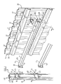
- a fencing system comprises a plurality of identical vertical posts 10, and one of which is shown in Figure 1, a pair of cross rails 11, again each of identical configuration and only one of which is shown, the rails 11 extending between and being releasably attached to the posts 10 by brackets 12 attached to the cross rails 11, which brackets 12 interengage attachment means 13 provided on the posts 10.
- the fencing system further comprises a fencing panel 14 which is adapted to be releasably connected to the cross rails 11 by a plurality of spring clips 15, although only one clip 15 is shown in Figure 1.
- the posts 10 are made of rolled steel section and are either directly embedded in the ground in concrete or the like, herein referred to as the ground, to a desired depth to give a fence of the required strength, or the posts 10 are received at their lower ends in a separate base unit which is engaged with the ground as hereinafter described.
- Each post 10 has a pair of planar side flanges 17a to which are connected a pair of end sections 17b, the posts thereby providing rails to enable a pair of rail plates 18a, 18b of the attachments means 13 to slide up and down.
- the rail plates 18a, 18b each have channels 19 corresponding to the rails.
- a threaded locking bolt 20 is provided on each rail plate 18a, 18b to enable the plate to be locked to the post at a desired height, so that the fencing system may be erected on uneven ground and the cross rails 11 maintained level.
- the opposite side of the post also has a pair of rail plates (not shown) to enable further cross rails 11 and hence further panels 14 to be attached to the post 10.
- plates are welded to the posts 10 which may be of a configuration, in order to provide rails on which the plates 18a, 18b can slide.
- the welded plates may only extend over part of the height of the post and of course, in this case, only limited height adjustment is therefore possible.
- the posts may comprise a plurality of component parts which extend generally upwardly and are connected in relatively inclined orientation such as an A frame.
- the posts 10 extend vertically and the cross rails horizontally, if desired the posts may be inclined to the vertical and the cross rails may extend in a direction inclined to the horizontal.
- each of the plates 18a, 18b is a U-shaped part, the free ends of the limbs 22, 23 of the part adjoining the plates 18a, 18b, the limbs 22, 23 each providing an abutment of a first attachment means.
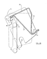
- the cross rails 11 each comprise a hollow section having an upper surface 25, and lower surface 26, a front surface 27 and a rear surface 28. It can be seen that the lower surface 26 is provided by the front 27 and rear 28 surfaces being joined so that the section is a substantially closed in Z-shape providing a recess 29 in the rear thereof.
- cross rails of other configuration may be provided if desired.
- the cross rails 11 are of such length as to extend between but not beyond a pair of posts 10.
- the cross rails are provided with second attachment means comprising, at each end 30 thereof a bracket 12 which comprises a planar element having an L-shaped upper hook formation comprises a slot 32 and a lower slot 33, whereby the laterally extending abutments 22, 23 of the posts may be received in the slots 32, 33, as shown in Figure 2a to connect the cross rail 11 to the posts 10.
- the brackets 12 are welded to the ends of the cross rail 11 as shown to permanently mount the bracket 12 on the cross rail 11.
- a cross rail 11 can be attached to the two posts as follows.
- the upper abutments 22 are each engaged in the ends of a horizontal part 36 of the upper slots 32 of the brackets 12 by hooking the brackets onto the abutments 22.
- the rail 11 is then rotated clockwise about an axis remote from the cross rail 11, to the dotted line position in Figure 2b wherein the lower abutments 23 are below the lower vertical slots 33 which provide a receiving formation.
- the rail 11 is permitted to lower by a vertical downward movement so that the upper abutments 22 of each post are received in the vertical parts 34 of slots 32 of each bracket 12, and the lower abutments 23 in the lower vertical slots 33.
- cross rail 11 will be attached to the posts 10 by being moved in a predetermined path comprising a rotational movement and a generally downwards movement. No locking means is necessary, the cross rail being retained in position solely by the weight thereof.
- a pair of transversely extending pegs may alternatively be provided which may be connected at their ends by a cross piece which projects transversely outwardly of the pegs to prevent the brackets 12 from transversely disengaging the pegs.
- the first attachment means comprises a pair of abutments.
- brackets 12 described require a vertical lifting or lowering movement and a rotational movement of the rail to release or connect the rail
- brackets may be provided which require only a vertical or rotational movement, or a movement along any other predetermined path transverse to the longitudinal axis of the cross rail.
- Such bracket is shown in Figure 7 and comprises a first hook part 132 connected to a second curved part 133.
- the bracket is engaged with the abutments 22, 23 which are horizontally displaced by first hooking the hook part 132 over the upper abutment 22 and rotating the cross rail to bring the lower curved part 133 below the lower abutment 23.
- the fencing panel 14 shown is corrugated over substantially the entire height thereof and thus provides a series of vertically extending troughs 37 and crests 38. Further, the side surfaces 39 are each provided with interengaging formations so that when further fencing panels 14 are attached to cross rails on the other side of the posts 10, so that the fencing panels 14 are side- by-side, a continuous fencing panel is provided whereby access cannot be gained to the rear of the panel. Thus, the length of the panels is equal to the spacing of the posts.
- the mounting bars 40 each have a first upper vertical flange 41 and a second lower vertical flange 42 with an outwardly projecting part 43 of corresponding configuration to the recess 29 of the closed in Z-shaped cross rails 11, between the flanges 41, 42 the projecting part 43 being adapted to be received in the recess 29.
- the upper and lower flanges 41, 42 each abut the crests 38 of the fencing panel 14 and are attached thereto by bolts 44, or alternatively rivets or any other fastening means.
- the troughs and crests may only extend over the height of the panel 14 in the region of the mounting bars 40. In either case, it will be appreciated that spaces 45 are provided between the troughs 37 of the fencing panel 14 and at the rear surface 40a of the mounting bars 40 in some of which spaces the spring clips 15 are each adapted to be received.
- the clips 15 each comprise a continuous clip made from spring steel rod, bent to provide a pair of first parts 46 which, when the projecting part 43 of the mounting bar is received in the recess 29 of the cross rail, are resiliently engaged over the top surface 25 of the cross rail, a hook H at the end of each part 46 engaging a projecting flange F formed at the junction of the top 25 and front 27 surfaces of the cross rail 11.
- the spring clip 15 further comprises a pair of second parts 47 which are received in the space 45 and each have a bent part 48 which is received in and resiliently grips a crank C in the rear 40a of the projecting part 43 of the mounting bar.
- the second parts 47 are connected by a U-shaped part 15a.
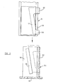
- a lower part 50 of a post 10 is shown for use with a base unit.
- a generally diagonally extending wedge plate 51 which has two transversely extending parts 52, 53 which each extend beyond the edge of the rails 18.
- the posts 10 are received in a base unit 54 which is engaged with the ground, rather than being embedded in the ground themselves, so that the posts 10 may be re- used.
- the base unit 54 comprises a base plate 55 to which are welded or otherwise secured three upstanding sides 56, 57, 58 to provide a three sided socket.
- the sides 56, 57, 58 are made as pressings in sheet steel but may be fabricated in any desired manner, and attached to the base plate 55 as required.
- each of the two opposite sides 56, 58 is a wedge bar 59 which extends diagonally at substantially the same angle as the wedge plate 51 on the posts 10.
- the post may thus be inserted into the base unit 54, the plates 51 being in contact with the bars 59 of the base unit 54 until the post comes to rest in the position as indicated in dotted lines in Figure 3.
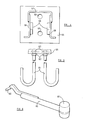
- the base unit 54 may be engaged with the ground in any desired manner.
- apertures such as shown at 60 in Figure 4 may be provided in each of which a J anchor bracket may be connected as shown at 61 in Figure 5 by bolts 62, 63 on either side of the 'base plate 55.
- the brackets 61 may be embedded in the ground or concrete and the base unit 54 may be bolted to the brackets 61 for example when the concrete has set.
- the posts 10, and base units 54 may be released when required and moved and re-used at a new location.
- the base plate 55 may be much larger in area than that shown and/or may be provided with an outrider so that the base unit 54 and hence fence, is free standing if required, the base plate 55 or the outrider where provided, may be pegged to the ground by removable pegs.
- the base unit 54 may be embedded in the ground or concrete but in this case, the posts are reusable but the base unit 54 remains embedded in the ground when the posts are removed.
- FIG. 6 a tool for removing the spring clips 15 is shown which has a a shank 65 from one end of which a transversely extending bar 66 extends.
- the bar 66 is hooked into a recess R ( Figure 2a) between the rear 40a of the mounting bar 40 and the spring clip in space 45.
- the clip 15 is then simply levered out of position.
- the end of the shank 65 remote from the bar 66 has a hammer head 67 formed thereon which may be used to assist in engaging the spring clips 15 in position.
- the posts 10 and/or cross rails 11 and/or brackets 12 and/or spring clips 15 may be modified as desired.
- the cross rails 11 may be of different configuration provided that the mounting bars 40 and spring clips 15 are correspondingly modified.
- abutments may be permanently attached to the posts.
- the plate need not have internal channels 19 as shown to engage with out-turned rails, but may if desired have inwardly extending pegs which engage with the rails 18.
- the fencing panel may be of alternative configuration to that shown in the drawings.
- the fencing panel may be planar and the mounting bars 40 corrugated in which case the cross rail 11 will need to be modifed accordingly.
- the clips 15 are received in the troughs provided by the mounting bars 40.
- the rail plates 18a, 18b and abutments 22, 23 and posts 10 may be modified so that the abutments project parallel or substantially parallel to the direction in which the cross rails with which they are to be engaged extend.
- the abutments 22, 23 may be provided on a suitable mount, on the cross rail and the bracket 12 on the posts 10, if required.
Landscapes
- Engineering & Computer Science (AREA)
- Architecture (AREA)
- Civil Engineering (AREA)
- Structural Engineering (AREA)
- Devices Affording Protection Of Roads Or Walls For Sound Insulation (AREA)
- Fencing (AREA)
Applications Claiming Priority (2)
| Application Number | Priority Date | Filing Date | Title |
|---|---|---|---|
| GB8106895 | 1981-03-05 | ||
| GB8106895 | 1981-03-05 |
Publications (1)
| Publication Number | Publication Date |
|---|---|
| EP0059913A1 true EP0059913A1 (de) | 1982-09-15 |
Family
ID=10520157
Family Applications (1)
| Application Number | Title | Priority Date | Filing Date |
|---|---|---|---|
| EP82101544A Withdrawn EP0059913A1 (de) | 1981-03-05 | 1982-03-01 | Mehrteiliges Zaunsystem |
Country Status (3)
| Country | Link |
|---|---|
| EP (1) | EP0059913A1 (de) |
| AU (1) | AU8112482A (de) |
| ES (1) | ES510168A0 (de) |
Cited By (3)
| Publication number | Priority date | Publication date | Assignee | Title |
|---|---|---|---|---|
| GB2199862A (en) * | 1986-12-30 | 1988-07-20 | Environmental Panelling Syst | A demountable panelling system |
| GB2303389A (en) * | 1995-07-07 | 1997-02-19 | James Cowie & Company | Removably supporting guard rail |
| WO2000004257A1 (en) * | 1998-07-16 | 2000-01-27 | Panzer, Aletta, Magdalena | Method of erecting a palisade |
Families Citing this family (3)
| Publication number | Priority date | Publication date | Assignee | Title |
|---|---|---|---|---|
| AU619647B2 (en) * | 1989-02-08 | 1992-01-30 | John Lysaght (Australia) Limited | Fence |
| AU622326B2 (en) * | 1990-05-23 | 1992-04-02 | Albrecht von Leszczynski | Fencing assembly |
| CN108401916B (zh) * | 2018-05-07 | 2024-06-14 | 中国大熊猫保护研究中心 | 一种大熊猫圈舍 |
Citations (3)
| Publication number | Priority date | Publication date | Assignee | Title |
|---|---|---|---|---|
| US3397866A (en) * | 1966-02-08 | 1968-08-20 | Reynolds Metals Co | Fence construction |
| GB1144471A (en) * | 1966-03-28 | 1969-03-05 | Bernard John Ennis | Improved fencing and like panelling |
| FR2450410A1 (fr) * | 1979-03-01 | 1980-09-26 | Fornells Sa | Treillage a geometrie variable avec dispositif de montage |
-
1982
- 1982-03-01 EP EP82101544A patent/EP0059913A1/de not_active Withdrawn
- 1982-03-04 AU AU81124/82A patent/AU8112482A/en not_active Abandoned
- 1982-03-05 ES ES510168A patent/ES510168A0/es active Granted
Patent Citations (3)
| Publication number | Priority date | Publication date | Assignee | Title |
|---|---|---|---|---|
| US3397866A (en) * | 1966-02-08 | 1968-08-20 | Reynolds Metals Co | Fence construction |
| GB1144471A (en) * | 1966-03-28 | 1969-03-05 | Bernard John Ennis | Improved fencing and like panelling |
| FR2450410A1 (fr) * | 1979-03-01 | 1980-09-26 | Fornells Sa | Treillage a geometrie variable avec dispositif de montage |
Cited By (5)
| Publication number | Priority date | Publication date | Assignee | Title |
|---|---|---|---|---|
| GB2199862A (en) * | 1986-12-30 | 1988-07-20 | Environmental Panelling Syst | A demountable panelling system |
| GB2199862B (en) * | 1986-12-30 | 1991-03-27 | Environmental Panelling Syst | A demountable panelling system |
| GB2303389A (en) * | 1995-07-07 | 1997-02-19 | James Cowie & Company | Removably supporting guard rail |
| GB2303389B (en) * | 1995-07-07 | 1998-12-16 | James Cowie & Company | Support assembly |
| WO2000004257A1 (en) * | 1998-07-16 | 2000-01-27 | Panzer, Aletta, Magdalena | Method of erecting a palisade |
Also Published As
| Publication number | Publication date |
|---|---|
| ES8303598A1 (es) | 1983-02-01 |
| ES510168A0 (es) | 1983-02-01 |
| AU8112482A (en) | 1982-09-09 |
Similar Documents
| Publication | Publication Date | Title |
|---|---|---|
| US5829549A (en) | Walkway with rail system | |
| US6554102B2 (en) | Dismountable facade scaffold | |
| US11208815B2 (en) | Scaffold ledger | |
| US6015139A (en) | Anchor for guard rail system on structural grating floors | |
| US10676943B2 (en) | Concrete form panel and a fastening system and method for fastening form hardware on the concrete form panel | |
| US5259477A (en) | Collapsible scaffold bracket | |
| US6557666B1 (en) | Modular hoarding system | |
| MXPA00007528A (es) | Sistema de montaje para ac cesorio de anaquel para un conjunto de gabinete. | |
| WO1990000657A1 (en) | A stanchion assembly | |
| US20050189172A1 (en) | Ladder safety cage | |
| EP0059913A1 (de) | Mehrteiliges Zaunsystem | |
| EP1072736A1 (de) | Schutzvorrichtung | |
| US6276668B1 (en) | Roof safety bracket system | |
| GB2094368A (en) | Fence | |
| WO1991006725A1 (en) | Modular building systems | |
| GB2094369A (en) | Fence | |
| US20080264725A1 (en) | Hook-On Scaffold | |
| US20020166722A1 (en) | Mobile outrigger scaffolding system | |
| WO1993009313A1 (en) | Stanchions for steel framed buildings | |
| GB2241721A (en) | Security fencing with concealed fastening means | |
| CN210396066U (zh) | 自锁式悬挑梁、承载装置及作业平台 | |
| US20250122735A1 (en) | Work platform | |
| AU667061B2 (en) | Scaffolding system | |
| US20250305321A1 (en) | Connection system | |
| CA1263043A (en) | Modular hoarding assembly |
Legal Events
| Date | Code | Title | Description |
|---|---|---|---|
| PUAI | Public reference made under article 153(3) epc to a published international application that has entered the european phase |
Free format text: ORIGINAL CODE: 0009012 |
|
| AK | Designated contracting states |
Designated state(s): BE DE FR NL |
|
| STAA | Information on the status of an ep patent application or granted ep patent |
Free format text: STATUS: THE APPLICATION IS DEEMED TO BE WITHDRAWN |
|
| 18D | Application deemed to be withdrawn |
Effective date: 19830822 |
|
| RIN1 | Information on inventor provided before grant (corrected) |
Inventor name: LOVERING, DENNIS WILLIAM Inventor name: MOREBY, JOHN |