EP0059924A1 - Dispositif de commande pour véhicules électriques entraînés par un moteur à induction - Google Patents
Dispositif de commande pour véhicules électriques entraînés par un moteur à induction Download PDFInfo
- Publication number
- EP0059924A1 EP0059924A1 EP82101599A EP82101599A EP0059924A1 EP 0059924 A1 EP0059924 A1 EP 0059924A1 EP 82101599 A EP82101599 A EP 82101599A EP 82101599 A EP82101599 A EP 82101599A EP 0059924 A1 EP0059924 A1 EP 0059924A1
- Authority
- EP
- European Patent Office
- Prior art keywords
- inverter
- frequency
- output
- voltage
- control apparatus
- Prior art date
- Legal status (The legal status is an assumption and is not a legal conclusion. Google has not performed a legal analysis and makes no representation as to the accuracy of the status listed.)
- Granted
Links
- 230000006698 induction Effects 0.000 title claims abstract description 29
- 230000010355 oscillation Effects 0.000 abstract description 26
- 239000003990 capacitor Substances 0.000 description 15
- 230000007423 decrease Effects 0.000 description 7
- 230000003247 decreasing effect Effects 0.000 description 7
- 238000010586 diagram Methods 0.000 description 5
- 230000001172 regenerating effect Effects 0.000 description 4
- 238000001514 detection method Methods 0.000 description 3
- 230000010363 phase shift Effects 0.000 description 3
- 230000003111 delayed effect Effects 0.000 description 2
- 230000008033 biological extinction Effects 0.000 description 1
- 230000000694 effects Effects 0.000 description 1
- 238000012423 maintenance Methods 0.000 description 1
- 230000008929 regeneration Effects 0.000 description 1
- 238000011069 regeneration method Methods 0.000 description 1
- 238000005096 rolling process Methods 0.000 description 1
- 239000004065 semiconductor Substances 0.000 description 1
- 230000000087 stabilizing effect Effects 0.000 description 1
Images

Classifications
-
- B—PERFORMING OPERATIONS; TRANSPORTING
- B60—VEHICLES IN GENERAL
- B60L—PROPULSION OF ELECTRICALLY-PROPELLED VEHICLES; SUPPLYING ELECTRIC POWER FOR AUXILIARY EQUIPMENT OF ELECTRICALLY-PROPELLED VEHICLES; ELECTRODYNAMIC BRAKE SYSTEMS FOR VEHICLES IN GENERAL; MAGNETIC SUSPENSION OR LEVITATION FOR VEHICLES; MONITORING OPERATING VARIABLES OF ELECTRICALLY-PROPELLED VEHICLES; ELECTRIC SAFETY DEVICES FOR ELECTRICALLY-PROPELLED VEHICLES
- B60L9/00—Electric propulsion with power supply external to the vehicle
- B60L9/16—Electric propulsion with power supply external to the vehicle using AC induction motors
- B60L9/18—Electric propulsion with power supply external to the vehicle using AC induction motors fed from DC supply lines
- B60L9/22—Electric propulsion with power supply external to the vehicle using AC induction motors fed from DC supply lines polyphase motors
-
- B—PERFORMING OPERATIONS; TRANSPORTING
- B60—VEHICLES IN GENERAL
- B60L—PROPULSION OF ELECTRICALLY-PROPELLED VEHICLES; SUPPLYING ELECTRIC POWER FOR AUXILIARY EQUIPMENT OF ELECTRICALLY-PROPELLED VEHICLES; ELECTRODYNAMIC BRAKE SYSTEMS FOR VEHICLES IN GENERAL; MAGNETIC SUSPENSION OR LEVITATION FOR VEHICLES; MONITORING OPERATING VARIABLES OF ELECTRICALLY-PROPELLED VEHICLES; ELECTRIC SAFETY DEVICES FOR ELECTRICALLY-PROPELLED VEHICLES
- B60L9/00—Electric propulsion with power supply external to the vehicle
- B60L9/005—Interference suppression
-
- H—ELECTRICITY
- H02—GENERATION; CONVERSION OR DISTRIBUTION OF ELECTRIC POWER
- H02P—CONTROL OR REGULATION OF ELECTRIC MOTORS, ELECTRIC GENERATORS OR DYNAMO-ELECTRIC CONVERTERS; CONTROLLING TRANSFORMERS, REACTORS OR CHOKE COILS
- H02P23/00—Arrangements or methods for the control of AC motors characterised by a control method other than vector control
- H02P23/06—Controlling the motor in four quadrants
- H02P23/07—Polyphase or monophase asynchronous induction motors
-
- B—PERFORMING OPERATIONS; TRANSPORTING
- B60—VEHICLES IN GENERAL
- B60L—PROPULSION OF ELECTRICALLY-PROPELLED VEHICLES; SUPPLYING ELECTRIC POWER FOR AUXILIARY EQUIPMENT OF ELECTRICALLY-PROPELLED VEHICLES; ELECTRODYNAMIC BRAKE SYSTEMS FOR VEHICLES IN GENERAL; MAGNETIC SUSPENSION OR LEVITATION FOR VEHICLES; MONITORING OPERATING VARIABLES OF ELECTRICALLY-PROPELLED VEHICLES; ELECTRIC SAFETY DEVICES FOR ELECTRICALLY-PROPELLED VEHICLES
- B60L2200/00—Type of vehicles
- B60L2200/26—Rail vehicles
-
- B—PERFORMING OPERATIONS; TRANSPORTING
- B60—VEHICLES IN GENERAL
- B60L—PROPULSION OF ELECTRICALLY-PROPELLED VEHICLES; SUPPLYING ELECTRIC POWER FOR AUXILIARY EQUIPMENT OF ELECTRICALLY-PROPELLED VEHICLES; ELECTRODYNAMIC BRAKE SYSTEMS FOR VEHICLES IN GENERAL; MAGNETIC SUSPENSION OR LEVITATION FOR VEHICLES; MONITORING OPERATING VARIABLES OF ELECTRICALLY-PROPELLED VEHICLES; ELECTRIC SAFETY DEVICES FOR ELECTRICALLY-PROPELLED VEHICLES
- B60L2220/00—Electrical machine types; Structures or applications thereof
- B60L2220/10—Electrical machine types
- B60L2220/12—Induction machines
Definitions
- This invention relates to an improvement of a control apparatus for an electric car propelled by an induction motor in which electric power is supplied from DC power supply through an invertor to an induction motor so as to drive the rolling stock.
- DC motors have been used as traction motors for many years, and use of induction motors has been discussed from old times because induction motors need no maintenance, are easy to make in small-size and have excellent adhesion characteristics.
- the power converter there are used an inverter in a DC electric railway, and the combination of a converter and an inverter or a frequency converter in an AC electric railway. In either case, use of an inverter is advantageous.
- the output frequency of this inverter is controlled to be a frequency obtained by adding the slip frequency of an induction motor to the speed of a car upon power running, and to be a frequency obtained by subtracting a slip frequency from the speed of a car upon regenerative braking.
- the output voltage is desirably controlled to be proportional to the output frequency, and to do so, two control systems can be considered. First, the voltage is adjusted by a current-constant control system, and as a result the output voltage of the inverter is approximately proportional to the output frequency. Second, a voltage control system arranged to produce a voltage proportional to the frequency is used to maintain the motor current approximately constant.
- a filter circuit is inserted between the DC power source and the inverter, and this filter circuit is arranged to have its resonant frequency lower than 50 to 60 Hz in order to prevent a track circuit relay for the operation of a crossing alarm or the like from malfunctioning.
- the resonant frequency of the filter circuit can not practically be reduced to a value lower than the lowest frequency (several Hz) of the inverter from the consideration of the size of its reactor and capacitor.
- This electrical oscillation causes the commutation of inverter to fail the torque of induction motor to oscillate, and the ride in the car to be uncomfortable.
- detection is made of the oscillating change of electrical quantity in an electrical circuit between the DC power supply and the induction motor, and the detected output is used to adjust the output voltage of the inverter.
- the output voltage from the inverter has a maximum level which is low as compared with the output frequency associated therewith.
- the oscillation can no longer be suppressed by the adjustment of the output voltage, but the output frequency of the inverter can be increased and decreased yet. If the output frequency of the inverter is increased and decreased at a given speed, the motor current can be increased and decreased respectively and also the above oscillation can be suppressed.
- the PWM inverter has a stepwise voltage change when the output voltage is increased to the maximum as described later. If the filter circuit resonates to the stepwise voltage change, the voltage from the PWM inverter in the maximum output voltage condition can not be adjusted continuously, and therefore it is ineffective to suppress the oscillation.
- the electrical oscillation can be suppressed by adjusting the operating frequency of the inverter.
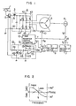
- a current collected by a pantograph 2 from a DC power supply or power line 1 is supplied through a filter circuit 3 to a three-phase inverter 4.
- the L-C filter circuit 3 is consisted of a reactor 31 and a capacitor 32.
- the inverter 4 is an inverter chiefly having gate-turn off thyristors (GTO) 41 to 46 capable of pulse width modulation (PWM), or a general type thyristor inverter.
- GTO gate-turn off thyristors
- PWM pulse width modulation
- the output of the inverter 4, or a three-phase AC of variable frequency and variable voltage is applied to a three-phase induction motor 5.
- the motor 5 drives the electric car and also allows a pulse generator 6 to rotate to generate a speed frequency signal fn corresponding to the speed of the electric car.
- the electric car also has a motor current command Ip setting-up device 9, the output Ip from which is compared with an output I from a motor current detector 10 by a comparator 11, thus a duty ratio command y being produced from the comparator 11.
- the inverter operation frequency command f and duty ratio (also called the modulation degree corresponding to the output voltage) command y thus produced are applied to a PWM- or simple- inverter control apparatus 12.
- the PWM inverter control apparatus 12 is well known, for example, in Hitachi Review, Vol. 61, No. 5 (1979-5), p. 27 to 32, particularly in the modulator section and gate processing signal circuit in Fig. 6 at p. 30.
- the induction motor 5 can be controlled in its frequency and voltage so that the motor current I M follows the set-up value Ip with the set-up slip frequency fs.
- a control system can also be provided which controls the voltage to vary as the frequency, or the current control system can be replaced by this voltage control system.
- a current transformer 13 with an air gap can detect an AC component of the line current.
- the output of the transformer 13 is negatively fed back to the comparator 11 within the current control system, through a phase shift circuit 14 and a band-pass filter circuit 15.
- the phase shift circuit 14 is formed of a resistor 141 and a choke coil 142 connected in series. The voltage across the choke coil 142 results from delaying the output voltage of the transformer 13 by 90 degrees.
- the output of the current transformer 13 with an air gap can be regarded as a constant current source, and thus the voltage drop e R across the resistor 141 is given by where i represents the current, R the resistance value (Q) of the resistor 141, and L the inductance (H) of the choke coil 142. If the internal resistance of the choke coil is such smaller than the resistance R, the voltage e L across the choke coil 142 is given by and therefore it leads the e R by 90°. If this voltage is inverted in its polarity, the output by the current transformer 13 can be delayed by 90°.
- the band-pass filter circuit 15 is formed of an operational amplifier 151, resistors 152, 153 and 154 and capacitors 155 and 156.
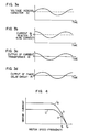
- the gain and phase characteristics of the band-pass filter circuit 15, as shown in Fig. 2, provides a high gain and in-phase input and output at around the resonant frequency, fr of the filter circuit 3.
- Fig. 3 shows the voltage and current waveform of each part, assuming that the output of the band-pass filter circuit 15 is not applied to the comparator 11. The oscillation suppressing operation will be described with reference to Fig. 3.
- the current in the reactor 31, or the line current leads the voltage across the capacitor 32 by about 90° as shown in Fig. 3b.
- the oscillating portion of the line current (AC component) is detected by the current transformer 13 with an air gap as shown in Fig. 3C.
- the output of the current transformer 13 is applied to the phase shift circuit 14, which then produces an output delayed about 90° with respect to the input, as shown in Fig. 3d.
- This output is applied to the band-pass filter circuit 15 where it is amplified because the band-pass filter circuit 15 has a high gain at the resonant frequency of the filter 3.
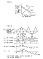
- Fig. 4 shows the speed vs. current characteristics of the motor to which reference is made in explaining the oscillation suppressing operation. It is assumed that the car is running at the frequency f l , or at point a on the current characteristic curve 11at a certain duty ratio y l . At this time, if the oscillation of the voltage across the capacitor 32 tends to increase, the duty ratio y is increased with the result that the operating point moves to the current characteristic curve I 2 , or from point a to b. Thus, the motor current increases to suppress the rise of the voltage across the capacitor 32.
- Fig. 5 shows the frequency ratio as the number of pulses n/Hz.
- the output voltage E from the inverter (proportional to the duty ratio y) is changed stepwise with the operation frequency of the inverter.
- the filter circuit 3 resonates to the stepwise increase of voltage to induce an electrical oscillation as set forth above. However, the output voltage from the inverter can no longer be adjusted continuously and this can not be suppressed by the apparatus of Fig. 1.
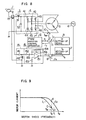
- the output of the band-pass filter circuit 15 is fed back to the adding-or-subtracting device 8 within the frequency control system. That is, in Fig. 9, it is assumed that the car.is running at point c on the current characteristic curve I I with the inverter operation frequency f l and set-up slip frequency f s1 .
- Symbol f represents the frequency corresponding to the speed of the car.
- the tendency of the voltage across the capacitor 32 to increase having an oscillation is detected from the increase of the line current, and the operation frequency is increased to f .
- the electrical oscillation is suppressed beforehand and as a result, current induced interference, commutation failure of the inverter and uncomfortableness in riding in car can be prevented which are caused by the electrical oscillation.
Landscapes
- Engineering & Computer Science (AREA)
- Power Engineering (AREA)
- Life Sciences & Earth Sciences (AREA)
- Sustainable Development (AREA)
- Sustainable Energy (AREA)
- Transportation (AREA)
- Mechanical Engineering (AREA)
- Electric Propulsion And Braking For Vehicles (AREA)
- Control Of Ac Motors In General (AREA)
Applications Claiming Priority (2)
| Application Number | Priority Date | Filing Date | Title |
|---|---|---|---|
| JP56029911A JPS57145503A (en) | 1981-03-04 | 1981-03-04 | Controlling device of induction motor driven electric motor vehicle |
| JP29911/81 | 1981-03-04 |
Publications (2)
| Publication Number | Publication Date |
|---|---|
| EP0059924A1 true EP0059924A1 (fr) | 1982-09-15 |
| EP0059924B1 EP0059924B1 (fr) | 1985-01-23 |
Family
ID=12289167
Family Applications (1)
| Application Number | Title | Priority Date | Filing Date |
|---|---|---|---|
| EP82101599A Expired EP0059924B1 (fr) | 1981-03-04 | 1982-03-02 | Dispositif de commande pour véhicules électriques entraînés par un moteur à induction |
Country Status (3)
| Country | Link |
|---|---|
| EP (1) | EP0059924B1 (fr) |
| JP (1) | JPS57145503A (fr) |
| DE (1) | DE3261993D1 (fr) |
Cited By (8)
| Publication number | Priority date | Publication date | Assignee | Title |
|---|---|---|---|---|
| EP0217411A3 (en) * | 1985-10-04 | 1988-04-06 | Hitachi, Ltd. | Apparatus for controlling electric vehicle using induction motor |
| EP0267548A3 (en) * | 1986-11-14 | 1989-02-22 | Bbc Brown Boveri Aktiengesellschaft | Device for control of an inverter fed rotating field macdevice for control of an inverter fed rotating field machine hine |
| AU581797B2 (en) * | 1986-01-13 | 1989-03-02 | Hitachi Limited | A control apparatus for pulse width modulation inverters |
| EP0325377A3 (fr) * | 1988-01-21 | 1990-06-13 | Mitsubishi Denki Kabushiki Kaisha | Appareil de régulation pour un véhicule électrique |
| EP0371427A3 (en) * | 1988-11-29 | 1990-07-04 | Hitachi, Ltd. | An arrangement for preventing inductive interference in electric car |
| EP0777587A4 (fr) * | 1995-06-13 | 1998-08-26 | Abb Daimler Benz Transp | Systeme de detection d'interference electromagnetique pour des vehicules de transport en commun a propulsion electrique |
| EP4079562A1 (fr) * | 2021-04-19 | 2022-10-26 | ABB Schweiz AG | Procédé et organe de commande pour commander un véhicule, programme informatique et support lisible par ordinateur |
| CN118092174A (zh) * | 2024-02-27 | 2024-05-28 | 超同步股份有限公司 | 一种智能配置驱动器参数的五轴机床辅助方法及系统 |
Families Citing this family (11)
| Publication number | Priority date | Publication date | Assignee | Title |
|---|---|---|---|---|
| JP2551549B2 (ja) * | 1983-09-08 | 1996-11-06 | 株式会社日立製作所 | 誘導電動機式電気車の制御装置 |
| JPH0746918B2 (ja) * | 1987-06-03 | 1995-05-17 | 株式会社日立製作所 | 電力変換装置 |
| JP2677804B2 (ja) * | 1987-11-27 | 1997-11-17 | 株式会社日立製作所 | インバータ装置の起動・停止方法 |
| JP2732619B2 (ja) * | 1988-11-17 | 1998-03-30 | 株式会社東芝 | 電気車制御装置 |
| JPH02119573A (ja) * | 1989-09-20 | 1990-05-07 | Hitachi Ltd | 電力変換装置 |
| JPH06209579A (ja) * | 1993-12-01 | 1994-07-26 | Hitachi Ltd | 電力変換装置 |
| JP4013483B2 (ja) | 2001-02-13 | 2007-11-28 | 株式会社日立製作所 | 電力変換器の制御装置 |
| JP3760280B2 (ja) | 2001-08-29 | 2006-03-29 | 株式会社日立製作所 | 直流機器及びこれを用いた車両 |
| JP4838462B2 (ja) * | 2001-09-21 | 2011-12-14 | 富士重工業株式会社 | 電気自動車の制御装置 |
| JP2004104976A (ja) * | 2002-09-12 | 2004-04-02 | Toshiba Corp | 電力変換装置 |
| CN118696491A (zh) * | 2022-03-30 | 2024-09-24 | 株式会社日立制作所 | 车辆用驱动控制装置及其方法 |
Citations (3)
| Publication number | Priority date | Publication date | Assignee | Title |
|---|---|---|---|---|
| US3781614A (en) * | 1972-07-31 | 1973-12-25 | Westinghouse Air Brake Co | Induction motor control system |
| FR2451126A1 (fr) * | 1979-03-05 | 1980-10-03 | Hitachi Ltd | Appareil de commande pour vehicules electriques a moteur a induction |
| EP0022267A1 (fr) * | 1979-07-06 | 1981-01-14 | Hitachi, Ltd. | Système de commande de moteur à induction entraînant une voiture |
Family Cites Families (7)
| Publication number | Priority date | Publication date | Assignee | Title |
|---|---|---|---|---|
| US3764872A (en) * | 1972-06-13 | 1973-10-09 | Gen Electric | Stabilizing means for an a-c motor drive |
| US3753063A (en) * | 1972-06-13 | 1973-08-14 | Gen Electric | Stabilizing means for an a-c motor drive |
| JPS5827753B2 (ja) * | 1974-08-09 | 1983-06-11 | 三菱電機株式会社 | セイリユウソウチノ ダンピングカイロ |
| JPS5139809A (en) * | 1974-09-30 | 1976-04-03 | Tokyo Shibaura Electric Co | Inbaatano shuhasufurenzokuseigyohoshiki |
| JPS5228632A (en) * | 1975-08-28 | 1977-03-03 | Toshiba Corp | Non-failure power source |
| JPS6053557B2 (ja) * | 1978-05-30 | 1985-11-26 | 株式会社日立製作所 | 誘導電動機の制御装置 |
| JPS5556402A (en) * | 1978-10-20 | 1980-04-25 | Hitachi Ltd | Electric motor vehicle |
-
1981
- 1981-03-04 JP JP56029911A patent/JPS57145503A/ja active Granted
-
1982
- 1982-03-02 DE DE8282101599T patent/DE3261993D1/de not_active Expired
- 1982-03-02 EP EP82101599A patent/EP0059924B1/fr not_active Expired
Patent Citations (3)
| Publication number | Priority date | Publication date | Assignee | Title |
|---|---|---|---|---|
| US3781614A (en) * | 1972-07-31 | 1973-12-25 | Westinghouse Air Brake Co | Induction motor control system |
| FR2451126A1 (fr) * | 1979-03-05 | 1980-10-03 | Hitachi Ltd | Appareil de commande pour vehicules electriques a moteur a induction |
| EP0022267A1 (fr) * | 1979-07-06 | 1981-01-14 | Hitachi, Ltd. | Système de commande de moteur à induction entraînant une voiture |
Non-Patent Citations (1)
| Title |
|---|
| TECHNISCHE MITTEILUNGEN AEG-TELEFUNKEN, vol.67, no.1, 1977, Berlin (DE), G. CIESSOW et al.:"Drehstrom-Antriebssysteme fur Bahnfahrzeuge", pages 35-43 * |
Cited By (10)
| Publication number | Priority date | Publication date | Assignee | Title |
|---|---|---|---|---|
| EP0217411A3 (en) * | 1985-10-04 | 1988-04-06 | Hitachi, Ltd. | Apparatus for controlling electric vehicle using induction motor |
| US4757240A (en) * | 1985-10-04 | 1988-07-12 | Hitachi, Ltd. | Apparatus for controlling electric vehicle using induction motor |
| AU581797B2 (en) * | 1986-01-13 | 1989-03-02 | Hitachi Limited | A control apparatus for pulse width modulation inverters |
| EP0267548A3 (en) * | 1986-11-14 | 1989-02-22 | Bbc Brown Boveri Aktiengesellschaft | Device for control of an inverter fed rotating field macdevice for control of an inverter fed rotating field machine hine |
| EP0325377A3 (fr) * | 1988-01-21 | 1990-06-13 | Mitsubishi Denki Kabushiki Kaisha | Appareil de régulation pour un véhicule électrique |
| AU611987B2 (en) * | 1988-01-21 | 1991-06-27 | Mitsubishi Denki Kabushiki Kaisha | Control device for electric car |
| EP0371427A3 (en) * | 1988-11-29 | 1990-07-04 | Hitachi, Ltd. | An arrangement for preventing inductive interference in electric car |
| EP0777587A4 (fr) * | 1995-06-13 | 1998-08-26 | Abb Daimler Benz Transp | Systeme de detection d'interference electromagnetique pour des vehicules de transport en commun a propulsion electrique |
| EP4079562A1 (fr) * | 2021-04-19 | 2022-10-26 | ABB Schweiz AG | Procédé et organe de commande pour commander un véhicule, programme informatique et support lisible par ordinateur |
| CN118092174A (zh) * | 2024-02-27 | 2024-05-28 | 超同步股份有限公司 | 一种智能配置驱动器参数的五轴机床辅助方法及系统 |
Also Published As
| Publication number | Publication date |
|---|---|
| JPH0313802B2 (fr) | 1991-02-25 |
| EP0059924B1 (fr) | 1985-01-23 |
| JPS57145503A (en) | 1982-09-08 |
| DE3261993D1 (en) | 1985-03-07 |
Similar Documents
| Publication | Publication Date | Title |
|---|---|---|
| EP0059924B1 (fr) | Dispositif de commande pour véhicules électriques entraînés par un moteur à induction | |
| US4315203A (en) | Control system for induction motor-driven car | |
| US4327313A (en) | Control apparatus for electric car | |
| US5532569A (en) | Inverter control apparatus | |
| EP0488163A2 (fr) | Dispositif de commande pour un véhicule électrique | |
| US4697130A (en) | Induction motor regenerative brake control apparatus and method | |
| US4380724A (en) | Shunt field control apparatus and method | |
| US11845341B2 (en) | Operation of switching elements of an inverter of an in particular rail-bound vehicle driven by way of least one at least three-phase synchronous machine | |
| JPH02215996A (ja) | ターボ分子ポンプ駆動電源装置 | |
| JP2845093B2 (ja) | 交流電気車の制御装置 | |
| US4528487A (en) | Electric car control system | |
| JP2877577B2 (ja) | 交流電気車制御装置 | |
| JPH0197102A (ja) | 電気車制御装置 | |
| CA1070785A (fr) | Systeme moteur pour vehicule a chenille | |
| JP3153655B2 (ja) | 電気車制御装置 | |
| JPH0732607B2 (ja) | 電気車用電力変換器の制御装置 | |
| SU974531A1 (ru) | Устройство дл торможени трехфазного асинхронного электродвигател | |
| JP2592536B2 (ja) | 電力変換装置の制御装置 | |
| JPH053605A (ja) | 電気車制御装置 | |
| JPH0720396B2 (ja) | インバータ変調方法 | |
| JPH05308704A (ja) | 電気車の制御装置 | |
| JPS59201608A (ja) | 誘導電動機式電気車の制御装置 | |
| JPH0568162B2 (fr) | ||
| JP2732619B2 (ja) | 電気車制御装置 | |
| JPH0528957Y2 (fr) |
Legal Events
| Date | Code | Title | Description |
|---|---|---|---|
| PUAI | Public reference made under article 153(3) epc to a published international application that has entered the european phase |
Free format text: ORIGINAL CODE: 0009012 |
|
| AK | Designated contracting states |
Designated state(s): DE FR GB SE |
|
| 17P | Request for examination filed |
Effective date: 19821209 |
|
| GRAA | (expected) grant |
Free format text: ORIGINAL CODE: 0009210 |
|
| AK | Designated contracting states |
Designated state(s): DE FR GB SE |
|
| REF | Corresponds to: |
Ref document number: 3261993 Country of ref document: DE Date of ref document: 19850307 |
|
| ET | Fr: translation filed | ||
| PLBE | No opposition filed within time limit |
Free format text: ORIGINAL CODE: 0009261 |
|
| STAA | Information on the status of an ep patent application or granted ep patent |
Free format text: STATUS: NO OPPOSITION FILED WITHIN TIME LIMIT |
|
| 26N | No opposition filed | ||
| EAL | Se: european patent in force in sweden |
Ref document number: 82101599.7 |
|
| PGFP | Annual fee paid to national office [announced via postgrant information from national office to epo] |
Ref country code: FR Payment date: 19981215 Year of fee payment: 18 |
|
| PGFP | Annual fee paid to national office [announced via postgrant information from national office to epo] |
Ref country code: SE Payment date: 19981221 Year of fee payment: 18 |
|
| PGFP | Annual fee paid to national office [announced via postgrant information from national office to epo] |
Ref country code: GB Payment date: 19981224 Year of fee payment: 18 |
|
| PGFP | Annual fee paid to national office [announced via postgrant information from national office to epo] |
Ref country code: DE Payment date: 19990331 Year of fee payment: 18 |
|
| PG25 | Lapsed in a contracting state [announced via postgrant information from national office to epo] |
Ref country code: GB Free format text: LAPSE BECAUSE OF NON-PAYMENT OF DUE FEES Effective date: 20000302 |
|
| PG25 | Lapsed in a contracting state [announced via postgrant information from national office to epo] |
Ref country code: SE Free format text: LAPSE BECAUSE OF NON-PAYMENT OF DUE FEES Effective date: 20000303 |
|
| GBPC | Gb: european patent ceased through non-payment of renewal fee |
Effective date: 20000302 |
|
| EUG | Se: european patent has lapsed |
Ref document number: 82101599.7 |
|
| PG25 | Lapsed in a contracting state [announced via postgrant information from national office to epo] |
Ref country code: FR Free format text: LAPSE BECAUSE OF NON-PAYMENT OF DUE FEES Effective date: 20001130 |
|
| REG | Reference to a national code |
Ref country code: FR Ref legal event code: ST |
|
| PG25 | Lapsed in a contracting state [announced via postgrant information from national office to epo] |
Ref country code: DE Free format text: LAPSE BECAUSE OF NON-PAYMENT OF DUE FEES Effective date: 20010103 |