EP0059943A1 - Fuel injection pump for internal combustion engines - Google Patents
Fuel injection pump for internal combustion engines Download PDFInfo
- Publication number
- EP0059943A1 EP0059943A1 EP82101691A EP82101691A EP0059943A1 EP 0059943 A1 EP0059943 A1 EP 0059943A1 EP 82101691 A EP82101691 A EP 82101691A EP 82101691 A EP82101691 A EP 82101691A EP 0059943 A1 EP0059943 A1 EP 0059943A1
- Authority
- EP
- European Patent Office
- Prior art keywords
- fuel
- liquid fuel
- rotor
- valve
- pressure
- Prior art date
- Legal status (The legal status is an assumption and is not a legal conclusion. Google has not performed a legal analysis and makes no representation as to the accuracy of the status listed.)
- Granted
Links
- 239000000446 fuel Substances 0.000 title claims abstract description 42
- 238000002347 injection Methods 0.000 title claims description 18
- 239000007924 injection Substances 0.000 title claims description 18
- 238000002485 combustion reaction Methods 0.000 title claims description 7
- 239000007788 liquid Substances 0.000 claims 10
- 230000006835 compression Effects 0.000 claims 2
- 238000007906 compression Methods 0.000 claims 2
- 238000006073 displacement reaction Methods 0.000 description 2
- 230000000694 effects Effects 0.000 description 2
- 239000010763 heavy fuel oil Substances 0.000 description 2
- 230000002411 adverse Effects 0.000 description 1
- 238000010276 construction Methods 0.000 description 1
- 238000009877 rendering Methods 0.000 description 1
Images
Classifications
-
- F—MECHANICAL ENGINEERING; LIGHTING; HEATING; WEAPONS; BLASTING
- F02—COMBUSTION ENGINES; HOT-GAS OR COMBUSTION-PRODUCT ENGINE PLANTS
- F02M—SUPPLYING COMBUSTION ENGINES IN GENERAL WITH COMBUSTIBLE MIXTURES OR CONSTITUENTS THEREOF
- F02M41/00—Fuel-injection apparatus with two or more injectors fed from a common pressure-source sequentially by means of a distributor
- F02M41/08—Fuel-injection apparatus with two or more injectors fed from a common pressure-source sequentially by means of a distributor the distributor and pumping elements being combined
- F02M41/14—Fuel-injection apparatus with two or more injectors fed from a common pressure-source sequentially by means of a distributor the distributor and pumping elements being combined rotary distributor supporting pump pistons
- F02M41/1405—Fuel-injection apparatus with two or more injectors fed from a common pressure-source sequentially by means of a distributor the distributor and pumping elements being combined rotary distributor supporting pump pistons pistons being disposed radially with respect to rotation axis
- F02M41/1411—Fuel-injection apparatus with two or more injectors fed from a common pressure-source sequentially by means of a distributor the distributor and pumping elements being combined rotary distributor supporting pump pistons pistons being disposed radially with respect to rotation axis characterised by means for varying fuel delivery or injection timing
- F02M41/1427—Arrangements for metering fuel admitted to pumping chambers, e.g. by shuttles or by throttle-valves
-
- F—MECHANICAL ENGINEERING; LIGHTING; HEATING; WEAPONS; BLASTING
- F02—COMBUSTION ENGINES; HOT-GAS OR COMBUSTION-PRODUCT ENGINE PLANTS
- F02M—SUPPLYING COMBUSTION ENGINES IN GENERAL WITH COMBUSTIBLE MIXTURES OR CONSTITUENTS THEREOF
- F02M41/00—Fuel-injection apparatus with two or more injectors fed from a common pressure-source sequentially by means of a distributor
- F02M41/08—Fuel-injection apparatus with two or more injectors fed from a common pressure-source sequentially by means of a distributor the distributor and pumping elements being combined
- F02M41/14—Fuel-injection apparatus with two or more injectors fed from a common pressure-source sequentially by means of a distributor the distributor and pumping elements being combined rotary distributor supporting pump pistons
- F02M41/1405—Fuel-injection apparatus with two or more injectors fed from a common pressure-source sequentially by means of a distributor the distributor and pumping elements being combined rotary distributor supporting pump pistons pistons being disposed radially with respect to rotation axis
- F02M41/1411—Fuel-injection apparatus with two or more injectors fed from a common pressure-source sequentially by means of a distributor the distributor and pumping elements being combined rotary distributor supporting pump pistons pistons being disposed radially with respect to rotation axis characterised by means for varying fuel delivery or injection timing
- F02M41/1422—Injection being effected by means of a free-piston displaced by the pressure of fuel
Definitions
- This invention relates to a fuel injection pump for internal combustion engines provided with a solenoid valve to control the supply of injection fuel to the fuel distributor.
- solenoid valves for controlling the supply of injection fuel to the fuel distributor are generally disposed in such a manner that the longitudinal direction of the solenoid valves, i.e., the needle valve displacement, is the radial direction of the rotary distributor.
- the fuel injection pump is mounted so that the rotating shaft of the rotary distributor is parallel to the rotating shaft of the internal combustion engine.
- the injection pump is driven in synchronism with the engine .
- the object of this invention is to provide the fuel injection pump for internal combustion engines which overcomes the aforementioned conventional drawbacks and which is compact, light weight and almost free from the effect of the engine vibration on the solenoid valves.
- this invention is characterized in that the solenoid valves to control the supply of fuel to the rotary distributor are mounted in such a manner that its needle valves move in the direction tangent to the rotating circle of the rotary distributor.
- a rotary distributor 1 driven in synchronism with the internal combustion engine (not shown) is installed in a sleeve of a 2' body 2.
- a pressure pump rotor 3 is provided at one end of the distributor 1 and a rotating portion of the vane type supply pump 4 is installed at the other end of the distributor 1 .
- the supply pump 4 has an inlet 5 and an outlet 6 formed in the body 2, the inlet 5 being connected to the fuel source (not shown) during operation.
- the inlet 5 and the outlet 6 are interconnected by an orifice 7 size the of which is determined by the spring-loaded valve member 8 to adjust the pressure at the outlet 6 .
- the rotor 3 has a radial hole 9 formed therein into which a pair of slidable peungers 12, 12' are press-fitted. While the distributor 1 is rotating, the pair of plungers 12, 12' are slid inward by the action of the annular cam 10 through the roller intermediate member 11 , 11 ' both installed in the body 2.
- the radial hole 9 is communicated with one end of the longitudinal passage or central axial bore 13 in the distributor 1 in which a shuttle or free piston 14 is slidably disposed .
- the amount of displacement of the shuttle 14 is determined by a pair of stoppers 15, 15' disposed apart from the opposing ends of the shuttle 14 .
- a delivery passage 18 is formed extending from the action chamber 19 at the point beyond the extreme position of the shuttle 14 .
- the delivery passage 18, when the distributor is rotating, is brought into communication with a plurality of delivery ports 16, (Fig. 3) one at a time, the delivery ports 16 being formed in the sleeve 2' equiangularly spaced from each other.
- the delivery passage 18 is also communicated with each cylinder of the engine through the delivery port 16 and a pressure valve 17.
- the same number of equiangularly spaced inlet passages 21 as that of the delivery ports 16 are formed extending from the action chamber 19 at the point beyond the extreme position of the shuttle 14.
- the inlet passages 21 are brought into the inlet port 20 formed in the sleeve 2' .
- the inlet port 20 and the inlet passages 21 are so arranged that they will communicate with each other when at least the delivery passage 18 is not aligned with one of the delivery ports 16 .
- a relief passage 25 extends from the action chamber 19.
- the relief passage 25, when the distributor 1 is rotating, is brought into communication with the equiangularly spaced relief ports 22 (Fig. 5) the same number of the delivery ports 16 formed in the sleeve 2' .
- the relief passage 25 stops the further movement of the shuttle 14 and passes the residual fuel staying in the pressure pump chamber 23 into the storage groove 24 through the relief port 22.
- the communication between the relief port 22 and the relief passage 25 occurs when at least the delivery passage 18 is aligned with the delivery port 16; the communication between the timing port 26 and the timing passage 27 takes place when at least the delivery passage 18 is not aligned with the delivery port 16 .
- Two solenoid valves 28, 28' (Fig .2) are mounted to the body 2 in such a way that their valve needles 29 are disposed in the direction tangent to the rotating circle of the distributor 1 .
- the outlet 6 is always communicated with the suction space 33 at the mounting portion of the solenoid valve 28, via the outlet passage 30, the radial hole 31 and the longitudinal hole 32 formed in the body 2 .
- the solenoid valve 28 is actuated by the current generated by the control circuit. When energized, the solenoid valve 28 displaces the needle 29, letting the fuel in the suction space 33 adjusted at a certain pressure flow through the valve hole 34 into the throttle 35 where it is metered.
- the throttle 35 of the solenoid valve 28 is connected with the injection connecting hole 36, the inlet port 20.
- the solenoid valve 28' When the solenoid valve 28' is energized, the throttle 35' is connected with the timing connecting hole 37 and with the timing port 26.
- the inlet port 20 When the shuttle 14 is at the extreme position or limit position near the delivery passage 18, the inlet port 20 is aligned with one of the inlet passages 21 and the timing port 26 with one of the timing passages 27 .
- the needle 29 As the solenoid valve 28 is actuated by the electric control circuit, the needle 29 is shifted open and the fuel in the suction space 33 flows through the valve hole 34, the throttle 35 and the injection connecting hole 36 to reach the inlet port 20 from which it is further led into the action chamber 19 on the side of the delivery passage 18.
- the fuel sent to the action chamber 19 acts upon the shuttle 14 to move it toward the radial hole 9 and at the same time move the plunger 12 and 12' outward.
- the amount of fuel entering the radial hole 9 determines the timing at which the fuel begins to be injected and supplied to the engine .
- the operation of the injection pump is described in detail in the Japanese patent application Nt). 55-130684.
- the delivery passage 18 becomes aligned with one of the delivery ports 16 and the relief passage 25 with one of the relief ports 22.
- the plungers 12 are forced inwardly by the annular cam 10 and the shuttle 14 is pushed toward the limit position on the side of the delivery passage 18 by the fuel pressure in the pressure pump chamber 23.
- the fuel is injected from the action chamber 19 through the pressure valve 17 into the cylinder of the engine.
- the solenoid valve 28 is laterally disposed tangent to the rotating circle of the distributor 1, as shown in Figure 2. This makes it possible to mount the solenoid valve 28 without having to enlarge the body 2 in the radial direction of the distributor 1, rendering the injector pump compact and light. This construction has strong resistance against the vertical vibration of the injector pump and therefore reduces erroneous operation of the solenoid valve.
Landscapes
- Engineering & Computer Science (AREA)
- Chemical & Material Sciences (AREA)
- Combustion & Propulsion (AREA)
- Mechanical Engineering (AREA)
- General Engineering & Computer Science (AREA)
- Fuel-Injection Apparatus (AREA)
Abstract
Description
- This invention relates to a fuel injection pump for internal combustion engines provided with a solenoid valve to control the supply of injection fuel to the fuel distributor.
- In a fuel injection pump equipped with a fuel distributor, solenoid valves for controlling the supply of injection fuel to the fuel distributor are generally disposed in such a manner that the longitudinal direction of the solenoid valves, i.e., the needle valve displacement, is the radial direction of the rotary distributor. The fuel injection pump is mounted so that the rotating shaft of the rotary distributor is parallel to the rotating shaft of the internal combustion engine. The injection pump is driven in synchronism with the engine .
- Therefore, when the solenoid valves are mounted to the injection pump, not only does the outer diameter of the pump body become large but the pump weight also increases . Another disadvantage is that when the vibration generated by the engine is transmitted to the fuel injection pump, the direction of movement of the needles of the solenoid valves coincide with the direction of the engine vibration, giving adverse effect on the action of the solenoid valves. Such apparatus is disclosed in US Patent No. 3,628,895 issued on Dec. 21, 1971 .
- The object of this invention is to provide the fuel injection pump for internal combustion engines which overcomes the aforementioned conventional drawbacks and which is compact, light weight and almost free from the effect of the engine vibration on the solenoid valves.
- To achieve this object, this invention is characterized in that the solenoid valves to control the supply of fuel to the rotary distributor are mounted in such a manner that its needle valves move in the direction tangent to the rotating circle of the rotary distributor.
-
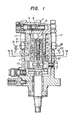
- Figure 1 is a cross sectional view of the fuel injection pump embodying the present invention; and
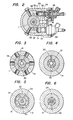
- Figures 2 through 6 are cross sectional view of main portions taken along the line II-II, IV-IV, V-V and VI-VI of Figure 1, respectively.
- Referring to Figures 1 through 6, a rotary distributor 1 driven in synchronism with the internal combustion engine (not shown) is installed in a sleeve of a 2
' body 2. A pressure pump rotor 3 is provided at one end of the distributor 1 and a rotating portion of the vane type supply pump 4 is installed at the other end of the distributor 1 . The supply pump 4 has aninlet 5 and anoutlet 6 formed in thebody 2, theinlet 5 being connected to the fuel source (not shown) during operation. Theinlet 5 and theoutlet 6 are interconnected by an orifice 7 size the of which is determined by the spring-loadedvalve member 8 to adjust the pressure at theoutlet 6 . - The rotor 3 has a radial hole 9 formed therein into which a pair of
slidable peungers 12, 12' are press-fitted. While the distributor 1 is rotating, the pair ofplungers 12, 12' are slid inward by the action of theannular cam 10 through the roller intermediate member 11 , 11 ' both installed in thebody 2. The radial hole 9 is communicated with one end of the longitudinal passage or centralaxial bore 13 in the distributor 1 in which a shuttle orfree piston 14 is slidably disposed . - The amount of displacement of the
shuttle 14 is determined by a pair ofstoppers 15, 15' disposed apart from the opposing ends of theshuttle 14 . - A
delivery passage 18 is formed extending from theaction chamber 19 at the point beyond the extreme position of theshuttle 14 . Thedelivery passage 18, when the distributor is rotating, is brought into communication with a plurality ofdelivery ports 16, (Fig. 3) one at a time, thedelivery ports 16 being formed in the sleeve 2' equiangularly spaced from each other. Thedelivery passage 18 is also communicated with each cylinder of the engine through thedelivery port 16 and apressure valve 17. The same number of equiangularly spacedinlet passages 21 as that of thedelivery ports 16 are formed extending from theaction chamber 19 at the point beyond the extreme position of theshuttle 14. When the distributor 1 is rotating, theinlet passages 21 are brought into theinlet port 20 formed in the sleeve 2' . Theinlet port 20 and theinlet passages 21 are so arranged that they will communicate with each other when at least thedelivery passage 18 is not aligned with one of thedelivery ports 16 . At the rear edge of theshuttle 14, arelief passage 25 extends from theaction chamber 19. Therelief passage 25, when the distributor 1 is rotating, is brought into communication with the equiangularly spaced relief ports 22 (Fig. 5) the same number of thedelivery ports 16 formed in the sleeve 2' . When not closed by the rear edge of theshuttle 14, therelief passage 25 stops the further movement of theshuttle 14 and passes the residual fuel staying in thepressure pump chamber 23 into thestorage groove 24 through therelief port 22. A plurality of equiangularly spacedtiming passages 27, the same number of thedelivery ports 16, extend from theaction chamber 19 at the point beyond the extreme position of theshuttle 14 on the side of therelief ports 22. Thetiming passages 27, when the distributor 1 is rotating, are brought into communication with thetiming port 26 formed in the sleeve 2' . - The communication between the
relief port 22 and therelief passage 25 occurs when at least thedelivery passage 18 is aligned with thedelivery port 16; the communication between thetiming port 26 and thetiming passage 27 takes place when at least thedelivery passage 18 is not aligned with thedelivery port 16 . - Two
solenoid valves 28, 28' (Fig .2) are mounted to thebody 2 in such a way that theirvalve needles 29 are disposed in the direction tangent to the rotating circle of the distributor 1 . Theoutlet 6 is always communicated with thesuction space 33 at the mounting portion of thesolenoid valve 28, via theoutlet passage 30, theradial hole 31 and thelongitudinal hole 32 formed in thebody 2 . - The
solenoid valve 28 is actuated by the current generated by the control circuit. When energized, thesolenoid valve 28 displaces theneedle 29, letting the fuel in thesuction space 33 adjusted at a certain pressure flow through thevalve hole 34 into thethrottle 35 where it is metered. Thethrottle 35 of thesolenoid valve 28 is connected with theinjection connecting hole 36, theinlet port 20. When the solenoid valve 28' is energized, the throttle 35' is connected with thetiming connecting hole 37 and with thetiming port 26. - When the
shuttle 14 is at the extreme position or limit position near thedelivery passage 18, theinlet port 20 is aligned with one of theinlet passages 21 and thetiming port 26 with one of thetiming passages 27 . As for the fuel to be injected, as thesolenoid valve 28 is actuated by the electric control circuit, theneedle 29 is shifted open and the fuel in thesuction space 33 flows through thevalve hole 34, thethrottle 35 and theinjection connecting hole 36 to reach theinlet port 20 from which it is further led into theaction chamber 19 on the side of thedelivery passage 18. The fuel sent to theaction chamber 19 acts upon theshuttle 14 to move it toward the radial hole 9 and at the same time move theplunger 12 and 12' outward. - Regarding the fuel that determines the injection timing, when the other solenoid valve 28' is actuated by the electric control circuit, the
needle 29 is shifted open letting the fuel in thesuction space 33 flow through thevalve hole 34, the thottle and thetiming connection hole 37 to reach thetiming port 26, from which the fuel further flows into theaction chamber 19 on the side of thetiming passage 27 and then into the radial hole 9. - The amount of fuel entering the radial hole 9 determines the timing at which the fuel begins to be injected and supplied to the engine . Thus, the greater the amount of fuel entering the radial hole 9, the greater the
plunger 12 will be shifted outwardly and the faster it will be driven inwardly by theannular cam 10 when the distributor 1 is rotating. The operation of the injection pump is described in detail in the Japanese patent application Nt). 55-130684. - As the distributor 1 further rotates, the
delivery passage 18 becomes aligned with one of thedelivery ports 16 and therelief passage 25 with one of therelief ports 22. As to the feeding of fuel, while the distributor 1 is rotating, theplungers 12 are forced inwardly by theannular cam 10 and theshuttle 14 is pushed toward the limit position on the side of thedelivery passage 18 by the fuel pressure in thepressure pump chamber 23. At the same time, the fuel is injected from theaction chamber 19 through thepressure valve 17 into the cylinder of the engine. - While the rear edge of the
shuttle 14 covers therelief pasage 25, theshuttle 14 is allowed to move. When therelief passage 25 is not closed, the further movement of theshuttle 14 is prevented and the residual fuel staying in thepressure pump chamber 23 is discharged through therelief passage 25, therelief port 22 and out into theoutlet passage 30. - As the distributor 1 continues to rotate, the abovementioned cycle is repeated.
- In this embodiment, the
solenoid valve 28 is laterally disposed tangent to the rotating circle of the distributor 1, as shown in Figure 2. This makes it possible to mount thesolenoid valve 28 without having to enlarge thebody 2 in the radial direction of the distributor 1, rendering the injector pump compact and light. This construction has strong resistance against the vertical vibration of the injector pump and therefore reduces erroneous operation of the solenoid valve.
Claims (3)
Applications Claiming Priority (2)
| Application Number | Priority Date | Filing Date | Title |
|---|---|---|---|
| JP56033952A JPS57148051A (en) | 1981-03-11 | 1981-03-11 | Fuel injection pump for internal combustion engine |
| JP33952/81 | 1981-03-11 |
Publications (2)
| Publication Number | Publication Date |
|---|---|
| EP0059943A1 true EP0059943A1 (en) | 1982-09-15 |
| EP0059943B1 EP0059943B1 (en) | 1987-02-25 |
Family
ID=12400827
Family Applications (1)
| Application Number | Title | Priority Date | Filing Date |
|---|---|---|---|
| EP82101691A Expired EP0059943B1 (en) | 1981-03-11 | 1982-03-04 | Fuel injection pump for internal combustion engines |
Country Status (4)
| Country | Link |
|---|---|
| US (1) | US4458649A (en) |
| EP (1) | EP0059943B1 (en) |
| JP (1) | JPS57148051A (en) |
| DE (1) | DE3275476D1 (en) |
Cited By (2)
| Publication number | Priority date | Publication date | Assignee | Title |
|---|---|---|---|---|
| US4488526A (en) * | 1981-09-28 | 1984-12-18 | Hitachi, Ltd. | Fuel injection pump for internal combustion engine |
| EP0100095B1 (en) * | 1982-07-26 | 1987-05-06 | Hitachi, Ltd. | Fuel injection pump |
Families Citing this family (3)
| Publication number | Priority date | Publication date | Assignee | Title |
|---|---|---|---|---|
| EP0118038A3 (en) * | 1983-02-04 | 1986-03-12 | Hitachi, Ltd. | Fuel injection pump |
| JPH0658100B2 (en) * | 1986-02-06 | 1994-08-03 | 日本電装株式会社 | Distributed fuel injection pump |
| KR100734013B1 (en) * | 2006-03-20 | 2007-06-29 | 주식회사 다산 | Heating device in the cabin using waste heat from engine |
Citations (4)
| Publication number | Priority date | Publication date | Assignee | Title |
|---|---|---|---|---|
| US3482519A (en) * | 1967-03-28 | 1969-12-09 | Cav Ltd | Liquid fuel pumping apparatus |
| DE1919707A1 (en) * | 1969-04-18 | 1970-11-12 | Bosch Gmbh Robert | Fuel injection pump for multi-cylinder internal combustion engines |
| FR2235276A2 (en) * | 1973-06-28 | 1975-01-24 | Bendix Corp | |
| GB2037365A (en) * | 1978-11-25 | 1980-07-09 | Lucas Industries Ltd | Liquid fuel injection pumping apparatus |
Family Cites Families (2)
| Publication number | Priority date | Publication date | Assignee | Title |
|---|---|---|---|---|
| GB1273140A (en) * | 1968-11-15 | 1972-05-03 | Lucas Industries Ltd | Liquid fuel injection pumping apparatus |
| US4382751A (en) * | 1980-02-14 | 1983-05-10 | Lucas Industries Limited | Fuel pumping apparatus |
-
1981
- 1981-03-11 JP JP56033952A patent/JPS57148051A/en active Pending
-
1982
- 1982-03-04 EP EP82101691A patent/EP0059943B1/en not_active Expired
- 1982-03-04 DE DE8282101691T patent/DE3275476D1/en not_active Expired
- 1982-03-08 US US06/355,693 patent/US4458649A/en not_active Expired - Fee Related
Patent Citations (4)
| Publication number | Priority date | Publication date | Assignee | Title |
|---|---|---|---|---|
| US3482519A (en) * | 1967-03-28 | 1969-12-09 | Cav Ltd | Liquid fuel pumping apparatus |
| DE1919707A1 (en) * | 1969-04-18 | 1970-11-12 | Bosch Gmbh Robert | Fuel injection pump for multi-cylinder internal combustion engines |
| FR2235276A2 (en) * | 1973-06-28 | 1975-01-24 | Bendix Corp | |
| GB2037365A (en) * | 1978-11-25 | 1980-07-09 | Lucas Industries Ltd | Liquid fuel injection pumping apparatus |
Cited By (2)
| Publication number | Priority date | Publication date | Assignee | Title |
|---|---|---|---|---|
| US4488526A (en) * | 1981-09-28 | 1984-12-18 | Hitachi, Ltd. | Fuel injection pump for internal combustion engine |
| EP0100095B1 (en) * | 1982-07-26 | 1987-05-06 | Hitachi, Ltd. | Fuel injection pump |
Also Published As
| Publication number | Publication date |
|---|---|
| DE3275476D1 (en) | 1987-04-02 |
| US4458649A (en) | 1984-07-10 |
| EP0059943B1 (en) | 1987-02-25 |
| JPS57148051A (en) | 1982-09-13 |
Similar Documents
| Publication | Publication Date | Title |
|---|---|---|
| EP0643221B1 (en) | Fuel Supply Apparatus | |
| US4693227A (en) | Multi-fuel injection system for an internal combustion engine | |
| US4625694A (en) | Fuel pumping apparatus | |
| EP0048432A2 (en) | Injection pump | |
| EP0524132B1 (en) | Fuel system for rotary distributor fuel injection pump | |
| US4831986A (en) | Fuel injection pump | |
| EP0429205A2 (en) | Fuel-distributing injector pump with electronic control | |
| US4879984A (en) | Fuel injection pump for internal combustion engines | |
| US4611566A (en) | Fuel injection pump for internal combustion engines | |
| EP0059943A1 (en) | Fuel injection pump for internal combustion engines | |
| EP0073410B1 (en) | Distribution type fuel injection pump | |
| EP0413453B1 (en) | Fuel pumping apparatus | |
| EP0055653B1 (en) | Distributor injection pump | |
| US2922371A (en) | Fuel injection pump | |
| US3744465A (en) | Hydraulic shuttle vavle for fuel injection pumps | |
| US3101079A (en) | Liquid fuel pumps for internal combustion engines | |
| US4681073A (en) | Fuel injection control valve | |
| EP0685641A2 (en) | Variable rate pump | |
| EP0094640A1 (en) | Fuel pumping apparatus | |
| US5044899A (en) | Fuel pumping apparatus | |
| EP0372713B1 (en) | Fuel injection pump | |
| EP0055654A1 (en) | Single solenoid floating piston distributor pump | |
| US3179100A (en) | Liquid fuel pumping apparatus for internal combustion engines | |
| EP0054497B1 (en) | Distribution injection pump for diesel engines | |
| EP0100095B1 (en) | Fuel injection pump |
Legal Events
| Date | Code | Title | Description |
|---|---|---|---|
| PUAI | Public reference made under article 153(3) epc to a published international application that has entered the european phase |
Free format text: ORIGINAL CODE: 0009012 |
|
| AK | Designated contracting states |
Designated state(s): BE CH DE FR GB IT NL SE |
|
| 17P | Request for examination filed |
Effective date: 19830214 |
|
| GRAA | (expected) grant |
Free format text: ORIGINAL CODE: 0009210 |
|
| AK | Designated contracting states |
Kind code of ref document: B1 Designated state(s): DE FR GB |
|
| REF | Corresponds to: |
Ref document number: 3275476 Country of ref document: DE Date of ref document: 19870402 |
|
| ET | Fr: translation filed | ||
| PLBE | No opposition filed within time limit |
Free format text: ORIGINAL CODE: 0009261 |
|
| STAA | Information on the status of an ep patent application or granted ep patent |
Free format text: STATUS: NO OPPOSITION FILED WITHIN TIME LIMIT |
|
| 26N | No opposition filed | ||
| PGFP | Annual fee paid to national office [announced via postgrant information from national office to epo] |
Ref country code: GB Payment date: 19920221 Year of fee payment: 11 |
|
| PGFP | Annual fee paid to national office [announced via postgrant information from national office to epo] |
Ref country code: FR Payment date: 19920313 Year of fee payment: 11 |
|
| PGFP | Annual fee paid to national office [announced via postgrant information from national office to epo] |
Ref country code: DE Payment date: 19920520 Year of fee payment: 11 |
|
| PG25 | Lapsed in a contracting state [announced via postgrant information from national office to epo] |
Ref country code: GB Effective date: 19930304 |
|
| GBPC | Gb: european patent ceased through non-payment of renewal fee |
Effective date: 19930304 |
|
| PG25 | Lapsed in a contracting state [announced via postgrant information from national office to epo] |
Ref country code: FR Effective date: 19931130 |
|
| PG25 | Lapsed in a contracting state [announced via postgrant information from national office to epo] |
Ref country code: DE Effective date: 19931201 |
|
| REG | Reference to a national code |
Ref country code: FR Ref legal event code: ST |