EP0059956A2 - Zurückgewinnung von Energie durch die Verdampfung von Flüssigerdgas - Google Patents
Zurückgewinnung von Energie durch die Verdampfung von Flüssigerdgas Download PDFInfo
- Publication number
- EP0059956A2 EP0059956A2 EP82101745A EP82101745A EP0059956A2 EP 0059956 A2 EP0059956 A2 EP 0059956A2 EP 82101745 A EP82101745 A EP 82101745A EP 82101745 A EP82101745 A EP 82101745A EP 0059956 A2 EP0059956 A2 EP 0059956A2
- Authority
- EP
- European Patent Office
- Prior art keywords
- multicomponent stream
- multicomponent
- liquefied
- stream
- partially
- Prior art date
- Legal status (The legal status is an assumption and is not a legal conclusion. Google has not performed a legal analysis and makes no representation as to the accuracy of the status listed.)
- Granted
Links
- 239000003949 liquefied natural gas Substances 0.000 title claims abstract description 28
- 230000008016 vaporization Effects 0.000 title claims abstract description 28
- 238000009834 vaporization Methods 0.000 title claims abstract description 13
- 238000011084 recovery Methods 0.000 title description 5
- 238000010792 warming Methods 0.000 claims abstract description 5
- VNWKTOKETHGBQD-UHFFFAOYSA-N methane Chemical compound C VNWKTOKETHGBQD-UHFFFAOYSA-N 0.000 claims description 30
- 238000009434 installation Methods 0.000 claims description 14
- 238000004064 recycling Methods 0.000 claims description 13
- 238000010438 heat treatment Methods 0.000 claims description 12
- 239000003345 natural gas Substances 0.000 claims description 12
- 238000001816 cooling Methods 0.000 claims description 11
- 238000000034 method Methods 0.000 claims description 11
- ATUOYWHBWRKTHZ-UHFFFAOYSA-N Propane Chemical compound CCC ATUOYWHBWRKTHZ-UHFFFAOYSA-N 0.000 claims description 10
- 239000000203 mixture Substances 0.000 claims description 7
- 238000005086 pumping Methods 0.000 claims description 7
- IJGRMHOSHXDMSA-UHFFFAOYSA-N Atomic nitrogen Chemical compound N#N IJGRMHOSHXDMSA-UHFFFAOYSA-N 0.000 claims description 6
- OTMSDBZUPAUEDD-UHFFFAOYSA-N Ethane Chemical compound CC OTMSDBZUPAUEDD-UHFFFAOYSA-N 0.000 claims description 6
- XLYOFNOQVPJJNP-UHFFFAOYSA-N water Substances O XLYOFNOQVPJJNP-UHFFFAOYSA-N 0.000 claims description 6
- 239000001294 propane Substances 0.000 claims description 5
- 239000007789 gas Substances 0.000 claims description 4
- 229910052757 nitrogen Inorganic materials 0.000 claims description 3
- 239000012080 ambient air Substances 0.000 claims description 2
- 239000012530 fluid Substances 0.000 description 14
- 239000007788 liquid Substances 0.000 description 6
- 239000012071 phase Substances 0.000 description 6
- 238000002485 combustion reaction Methods 0.000 description 5
- 229930195733 hydrocarbon Natural products 0.000 description 4
- 150000002430 hydrocarbons Chemical class 0.000 description 4
- 239000007791 liquid phase Substances 0.000 description 4
- OFBQJSOFQDEBGM-UHFFFAOYSA-N n-pentane Natural products CCCCC OFBQJSOFQDEBGM-UHFFFAOYSA-N 0.000 description 4
- 239000012808 vapor phase Substances 0.000 description 4
- VGGSQFUCUMXWEO-UHFFFAOYSA-N Ethene Chemical compound C=C VGGSQFUCUMXWEO-UHFFFAOYSA-N 0.000 description 2
- 239000005977 Ethylene Substances 0.000 description 2
- 239000001273 butane Substances 0.000 description 2
- NNPPMTNAJDCUHE-UHFFFAOYSA-N isobutane Chemical compound CC(C)C NNPPMTNAJDCUHE-UHFFFAOYSA-N 0.000 description 2
- QWTDNUCVQCZILF-UHFFFAOYSA-N isopentane Chemical compound CCC(C)C QWTDNUCVQCZILF-UHFFFAOYSA-N 0.000 description 2
- IJDNQMDRQITEOD-UHFFFAOYSA-N n-butane Chemical compound CCCC IJDNQMDRQITEOD-UHFFFAOYSA-N 0.000 description 2
- 239000003507 refrigerant Substances 0.000 description 2
- 230000009286 beneficial effect Effects 0.000 description 1
- AFABGHUZZDYHJO-UHFFFAOYSA-N dimethyl butane Natural products CCCC(C)C AFABGHUZZDYHJO-UHFFFAOYSA-N 0.000 description 1
- 230000005611 electricity Effects 0.000 description 1
- 239000000446 fuel Substances 0.000 description 1
- 239000007792 gaseous phase Substances 0.000 description 1
- 125000001475 halogen functional group Chemical group 0.000 description 1
- 239000001282 iso-butane Substances 0.000 description 1
- 238000004519 manufacturing process Methods 0.000 description 1
- 238000012986 modification Methods 0.000 description 1
- 230000004048 modification Effects 0.000 description 1
- 238000010248 power generation Methods 0.000 description 1
- QQONPFPTGQHPMA-UHFFFAOYSA-N propylene Natural products CC=C QQONPFPTGQHPMA-UHFFFAOYSA-N 0.000 description 1
- 125000004805 propylene group Chemical group [H]C([H])([H])C([H])([*:1])C([H])([H])[*:2] 0.000 description 1
- 238000005057 refrigeration Methods 0.000 description 1
- 239000013535 sea water Substances 0.000 description 1
- 239000002918 waste heat Substances 0.000 description 1
Images
Classifications
-
- F—MECHANICAL ENGINEERING; LIGHTING; HEATING; WEAPONS; BLASTING
- F01—MACHINES OR ENGINES IN GENERAL; ENGINE PLANTS IN GENERAL; STEAM ENGINES
- F01K—STEAM ENGINE PLANTS; STEAM ACCUMULATORS; ENGINE PLANTS NOT OTHERWISE PROVIDED FOR; ENGINES USING SPECIAL WORKING FLUIDS OR CYCLES
- F01K25/00—Plants or engines characterised by use of special working fluids, not otherwise provided for; Plants operating in closed cycles and not otherwise provided for
- F01K25/08—Plants or engines characterised by use of special working fluids, not otherwise provided for; Plants operating in closed cycles and not otherwise provided for using special vapours
- F01K25/10—Plants or engines characterised by use of special working fluids, not otherwise provided for; Plants operating in closed cycles and not otherwise provided for using special vapours the vapours being cold, e.g. ammonia, carbon dioxide, ether
-
- F—MECHANICAL ENGINEERING; LIGHTING; HEATING; WEAPONS; BLASTING
- F01—MACHINES OR ENGINES IN GENERAL; ENGINE PLANTS IN GENERAL; STEAM ENGINES
- F01K—STEAM ENGINE PLANTS; STEAM ACCUMULATORS; ENGINE PLANTS NOT OTHERWISE PROVIDED FOR; ENGINES USING SPECIAL WORKING FLUIDS OR CYCLES
- F01K25/00—Plants or engines characterised by use of special working fluids, not otherwise provided for; Plants operating in closed cycles and not otherwise provided for
- F01K25/06—Plants or engines characterised by use of special working fluids, not otherwise provided for; Plants operating in closed cycles and not otherwise provided for using mixtures of different fluids
-
- F—MECHANICAL ENGINEERING; LIGHTING; HEATING; WEAPONS; BLASTING
- F17—STORING OR DISTRIBUTING GASES OR LIQUIDS
- F17C—VESSELS FOR CONTAINING OR STORING COMPRESSED, LIQUEFIED OR SOLIDIFIED GASES; FIXED-CAPACITY GAS-HOLDERS; FILLING VESSELS WITH, OR DISCHARGING FROM VESSELS, COMPRESSED, LIQUEFIED, OR SOLIDIFIED GASES
- F17C9/00—Methods or apparatus for discharging liquefied or solidified gases from vessels not under pressure
- F17C9/02—Methods or apparatus for discharging liquefied or solidified gases from vessels not under pressure with change of state, e.g. vaporisation
- F17C9/04—Recovery of thermal energy
-
- F—MECHANICAL ENGINEERING; LIGHTING; HEATING; WEAPONS; BLASTING
- F17—STORING OR DISTRIBUTING GASES OR LIQUIDS
- F17C—VESSELS FOR CONTAINING OR STORING COMPRESSED, LIQUEFIED OR SOLIDIFIED GASES; FIXED-CAPACITY GAS-HOLDERS; FILLING VESSELS WITH, OR DISCHARGING FROM VESSELS, COMPRESSED, LIQUEFIED, OR SOLIDIFIED GASES
- F17C2221/00—Handled fluid, in particular type of fluid
- F17C2221/03—Mixtures
- F17C2221/032—Hydrocarbons
- F17C2221/033—Methane, e.g. natural gas, CNG, LNG, GNL, GNC, PLNG
-
- F—MECHANICAL ENGINEERING; LIGHTING; HEATING; WEAPONS; BLASTING
- F17—STORING OR DISTRIBUTING GASES OR LIQUIDS
- F17C—VESSELS FOR CONTAINING OR STORING COMPRESSED, LIQUEFIED OR SOLIDIFIED GASES; FIXED-CAPACITY GAS-HOLDERS; FILLING VESSELS WITH, OR DISCHARGING FROM VESSELS, COMPRESSED, LIQUEFIED, OR SOLIDIFIED GASES
- F17C2223/00—Handled fluid before transfer, i.e. state of fluid when stored in the vessel or before transfer from the vessel
- F17C2223/01—Handled fluid before transfer, i.e. state of fluid when stored in the vessel or before transfer from the vessel characterised by the phase
- F17C2223/0146—Two-phase
- F17C2223/0153—Liquefied gas, e.g. LPG, GPL
- F17C2223/0161—Liquefied gas, e.g. LPG, GPL cryogenic, e.g. LNG, GNL, PLNG
-
- F—MECHANICAL ENGINEERING; LIGHTING; HEATING; WEAPONS; BLASTING
- F17—STORING OR DISTRIBUTING GASES OR LIQUIDS
- F17C—VESSELS FOR CONTAINING OR STORING COMPRESSED, LIQUEFIED OR SOLIDIFIED GASES; FIXED-CAPACITY GAS-HOLDERS; FILLING VESSELS WITH, OR DISCHARGING FROM VESSELS, COMPRESSED, LIQUEFIED, OR SOLIDIFIED GASES
- F17C2223/00—Handled fluid before transfer, i.e. state of fluid when stored in the vessel or before transfer from the vessel
- F17C2223/03—Handled fluid before transfer, i.e. state of fluid when stored in the vessel or before transfer from the vessel characterised by the pressure level
- F17C2223/033—Small pressure, e.g. for liquefied gas
-
- F—MECHANICAL ENGINEERING; LIGHTING; HEATING; WEAPONS; BLASTING
- F17—STORING OR DISTRIBUTING GASES OR LIQUIDS
- F17C—VESSELS FOR CONTAINING OR STORING COMPRESSED, LIQUEFIED OR SOLIDIFIED GASES; FIXED-CAPACITY GAS-HOLDERS; FILLING VESSELS WITH, OR DISCHARGING FROM VESSELS, COMPRESSED, LIQUEFIED, OR SOLIDIFIED GASES
- F17C2225/00—Handled fluid after transfer, i.e. state of fluid after transfer from the vessel
- F17C2225/01—Handled fluid after transfer, i.e. state of fluid after transfer from the vessel characterised by the phase
- F17C2225/0107—Single phase
- F17C2225/0123—Single phase gaseous, e.g. CNG, GNC
-
- F—MECHANICAL ENGINEERING; LIGHTING; HEATING; WEAPONS; BLASTING
- F17—STORING OR DISTRIBUTING GASES OR LIQUIDS
- F17C—VESSELS FOR CONTAINING OR STORING COMPRESSED, LIQUEFIED OR SOLIDIFIED GASES; FIXED-CAPACITY GAS-HOLDERS; FILLING VESSELS WITH, OR DISCHARGING FROM VESSELS, COMPRESSED, LIQUEFIED, OR SOLIDIFIED GASES
- F17C2225/00—Handled fluid after transfer, i.e. state of fluid after transfer from the vessel
- F17C2225/03—Handled fluid after transfer, i.e. state of fluid after transfer from the vessel characterised by the pressure level
- F17C2225/036—Very high pressure, i.e. above 80 bars
-
- F—MECHANICAL ENGINEERING; LIGHTING; HEATING; WEAPONS; BLASTING
- F17—STORING OR DISTRIBUTING GASES OR LIQUIDS
- F17C—VESSELS FOR CONTAINING OR STORING COMPRESSED, LIQUEFIED OR SOLIDIFIED GASES; FIXED-CAPACITY GAS-HOLDERS; FILLING VESSELS WITH, OR DISCHARGING FROM VESSELS, COMPRESSED, LIQUEFIED, OR SOLIDIFIED GASES
- F17C2250/00—Accessories; Control means; Indicating, measuring or monitoring of parameters
- F17C2250/01—Intermediate tanks
-
- F—MECHANICAL ENGINEERING; LIGHTING; HEATING; WEAPONS; BLASTING
- F17—STORING OR DISTRIBUTING GASES OR LIQUIDS
- F17C—VESSELS FOR CONTAINING OR STORING COMPRESSED, LIQUEFIED OR SOLIDIFIED GASES; FIXED-CAPACITY GAS-HOLDERS; FILLING VESSELS WITH, OR DISCHARGING FROM VESSELS, COMPRESSED, LIQUEFIED, OR SOLIDIFIED GASES
- F17C2265/00—Effects achieved by gas storage or gas handling
- F17C2265/05—Regasification
-
- F—MECHANICAL ENGINEERING; LIGHTING; HEATING; WEAPONS; BLASTING
- F17—STORING OR DISTRIBUTING GASES OR LIQUIDS
- F17C—VESSELS FOR CONTAINING OR STORING COMPRESSED, LIQUEFIED OR SOLIDIFIED GASES; FIXED-CAPACITY GAS-HOLDERS; FILLING VESSELS WITH, OR DISCHARGING FROM VESSELS, COMPRESSED, LIQUEFIED, OR SOLIDIFIED GASES
- F17C2265/00—Effects achieved by gas storage or gas handling
- F17C2265/07—Generating electrical power as side effect
Definitions
- This invention relates to a method and an installation for recovering power from the vaporization of liquefied natural gas.
- U.S. Patents 3,293,850 and 3,992,891 disclose power recovery processes employing noncondensing gaseous heat exchange fluids during vaporization of the liquefied natural gas. Both patents require the use of fuel combustion to provide heat input to the exchanging systems. Cascade refrigeration systems for vaporizing liquefied natural gas streams, from which power is recovered by means of expanders, are shown in U.S. Patents 3,068,659 and 3,183,666. Both patents disclose the need for heat sources, such as waste heat means or natural gas combustion.
- a method for recovering power from the vaporization of liquefied natural gas comprises the steps of at least partially liquefying a first multicomponent stream with said liquefied natural gas as the liquefied gas is vaporized, pumping said at least partially liquefied first multicomponent stream to an elevated pressure, warming and at least partially vaporizing said first multicomponent stream by cooling and at least partially liquefying a second multicomponent stream, heating and fully vaporizing said first multicomponent stream, expanding said heated and vaporized first multicomponent stream through a first expander, recovering power from said first expander, recycling said expanded first multicomponent stream to be at least partially liquefied, pumping said at least partially liquefied multicomponent stream to an elevated pressure, heating and vaporizing said second multicomponent stream, expanding said second multicomponent stream through a second expander, recovering power from said second expander, and recycling said expanded second multicomponent stream to be at least partially liquefied by said first multicomponent
- the present invention also provides an installation for recovering power for the vaporization of liquefied natural gas, which installation comprises a main heat exchanger in which said liquefied natural gas can be warmed and vaporized by cooling and at least partially liquefying a first multicomponent stream, at least one pump for pressurizing said at least partially liquefied first multicomponent stream, at least one heat exchanger in which said liquefied first multicomponent stream can be warmed and at least partially vaporized by cooling and at least partially liquefying a second multicomponent stream, means for heating and fully vaporizing said first multicomponent stream, a first expander for expanding said heated multicomponent stream, a first conduit for recycling said first multicomponent stream from said first expander to said main heat exchanger, a pump for pressurizing said at least partially liquefied second multicomponent stream, means for heating said multicomponent stream to produce a vapor, a second expander through which said vapor can be expanded, a second conduit for recycling said expanded second multicomponent stream to said
- Natural gas is transported and stored in a liquefied condition in order to provide beneficial economic means for its handling prior to consumption, as in combustion.
- a significant amount of energy is expended in the liquefaction of natural gas at its source prior to transportation or storage. It would be particularly advantageous to be able to recover these energy inputs at the point where the liquefied natural gas is revaporized. It would also be advantageous in the revaporization of liquefied natural gas to avoid the combustion of even a small percentage of the gas in order to execute the revaporization process.
- the present invention is directed to such a revaporization process and installation wherein the energy of liquefaction is recovered without the need for the utilization or consumption of even a portion of the natural gas to form the heat of combustion. This objective is achieved with a minimum of capital outlay.
- a method for recovering power from the vaporization of liquefied natural gas comprises the steps of at least partially liquefying a first multicomponent stream with said liquefied natural gas as the liquefied gas is vaporized, pumping an at least partially liquefied first multicomponent stream to an elevated pressure, warming and at least partially vaporizing said first multicomponent stream by cooling and at least partially liquefying a second multicomponent stream, heating and fully vaporizing said first multicomponent stream, expanding said heated and vaporized first multicomponent stream through a first expander, recovering power from said first expander, recycling said expanded first multicomponent stream to be at least partially liquefied, pumping said at least partially liquefied second multicomponent stream to an elevated pressure, heating and vaporizing said second multicomponent stream, expanding said second multicomponent stream through a second expander, recovering power from said second expander, and recycling said expanded second multicomponent stream to be at least partially liquefied by said first multicomponent
- At least part of said natural gas is used to assist in cooling said second multicomponent stream.
- the multicomponent stream mixture could comprise a combination of two components, for example, two halo fluorocarbons.
- a multicomponent mixture comprising at least three components is preferred, for example, two hydrocarbons and nitrogen, three hydrocarbons or three hydrocarbons and nitrogen.
- Suitable hydrocarbons include methane, ethane, ethylene, propane, propylene, butane, isobutane, pentane, isopentane, and various, mixtures thereof.
- Particularly preferred as'a first multicomponent stream is a mixture comprising methane, ethane and propane.
- a particularly preferred mixture for the second multicomponent stream comprises ethane, propane and butane. The replacement of ethane with ethylene is also contemplated.
- the present invention also provides an installation for recovering power for the vaporization of liquefied natural gas, which installation comprises a main heat exchanger in which said liquefied natural gas can be warmed and vaporized by cooling and at least partially liquefying a first multicomponent stream, at least one pump for pressurizing said at least partially liquefied first multicomponent stream, at least one heat exchanger in which said liquefied first multicomponent stream can be warmed and at least partially vaporized by cooling, and at least partially liquefying a second multicomponent stream, means for heating and fully vaporizing said first multicomponent stream, a first expander for expanding said heated and vaporized first multicomponent stream, a first conduit for recycling said first multicomponent stream from said first expander to said main heat exchanger, a pump for pressurizing said at least partially liquefied second multicomponent stream, means for heating said second multicomponent stream to produce a vapor, a second expander through which said vapor can be expanded, a second conduit for recycling the said
- the installation could include an auxiliary heat exchanger which utilizes water of at least 32°F or ambient air to insure vaporization and proper pipeline temperature of the natural gas.
- the present invention specifically contemplates the recovery of energy from the expanders in the form of electricity produced from a generator connected to the expanders.
- the first multicomponent stream may include a phase separator for identifying and separating the vapor and liquid phase of the first multicomponent stream during the heat exchange function of said stream with the natural gas.
- a phase separator for identifying and separating the vapor and liquid phase of the first multicomponent stream during the heat exchange function of said stream with the natural gas.
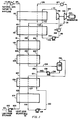
- the gaseous phase is warmed in heat exchanger 116, which is warmed by water at 60°F (15.56°C) and leaves the installation through conduit 117.
- the liquefied natural gas which is to be revaporized in the heat exchangers, passes through a series of exchange units 104, 106, 108, 110, 112 and 114.
- the revaporizing liquefied natural gas is exchanged with a countercurrent flowing stream of a multicomponent fluid passing through conduit 131 at the rate of 32,081 pound mole per hour.
- the multicomponent mixture comprises (by volume):
- the multicomponent fluid in conduit 131 enters the heat exchanger at exchange unit 112.
- the temperature of the multicomponent fluid at this point is -27.93°F (-33.3°C) at a pressure of 89 psia (6.14 bars A).
- the multicomponent fluid is then cooled through exchange units 112, 110 and 108 to a temperature of -186.43°F (-121.3°C) and at a pressure of 80 psi (5.52 bars A).
- the vapor and liquid multicomponent fluid stream then enters phase separator 135.
- the vaporous portion of the multicomponent stream leaves the phase separator 135 through conduit 136 and is reintroduced into the heat exchanger 106 for additional cooling.
- the vaporous multicomponent stream is liquefied in the lower series of heat exchangers 104, 106 and exits the exchangers through conduit 118 at a temperature of -237.75°F (-149.8°C).
- This liquid is then pumped through pump 119 and conduit 120 to a pressure of 340 psi (23.46 bars A) before being reintroduced into the heat exchanger 106 for warming.
- the liquid phase of the multicomponent fluid emanating from the bottom of phase separator 135 is conducted through conduit 138 to pump 139, wherein the pressure of the liquid is raised to 310 psia (21.39 bars A).
- the liquid is reintroduced into heat exchanger 108 and is combined with the previously separated vapor phase in conduit 122, which is now in the liquid phase.
- the remixed liquids rise through heat exchangers 108-114 to be rewarmed from a temperature at conduit 122 of -188.27°F (-122.3°C), and a pressure of 310 psia (21.39 bars A) to an exit temperature at conduit 126 of -27.84°F (-33.1°C), and a pressure of 245 psia (16.91 bars A) in a predominantly vaporous phase.
- Residual liquid phase components are vaporized in heat exchange unit 127, wherein the fluid is heated to 50°F (10°C) at a pressure of 240 psia (16.56 bars A) by water at 60°F (15.56°C).
- the heated fluid is expanded through expander 129 to a pressure of 89 psia (6.14 bars A).
- the expanded vaporous multicomponent fluid is then reintroduced through conduit 131 into heat exchanger l12 for recoupment of its heat content by the revaporizing natural gas.
- the upper heat exchange units 112 and 114 of the series of heat exchangers incorporate an additional heat exchange cycle of a multicomponent fluid stream.
- This additional cycle exchanges heat value with the first multicomponent fluid cycle, as well as with the revaporizing natural gas.
- the second multicomponent stream in conduit 141 consists of an entirely vapor phase at -19.87°F (-6.2°C) at a pressure of 24.49 psia (1.69 bars A).
- This second multicomponent stream consists of (by volume): This second multicomponent stream is cooled and liquefied through the heat exchange units 114 and 112 to a temperature of -50°F (-45.56°C) at a pressure of 21.49 psia (1.48 bars A).
- the second multicomponent fluid stream Upon leaving the heat exchangers, the second multicomponent fluid stream is pumped through pump 144 to a pressure of 87.50 psia (6.04 bars A) and is subsequently heated in heat exchanger 146 to a temperature of 50°F (10°C) by exchanging with water at 60°F (15.56°C). At this point, the second multicomponent stream is entirely in the vapor phase and is expanded through expander 148 to complete its cycle. The expansion of the second multicomponent fluid stream is from 87.5 psia to 24.49 psia.
- Power from the expanders 129 and 148 is transmitted to a generator 130 for the production of electrical power.
- the generator produces a net 7,453 kilowatts of electrical power after providing the power for pumps 119, 139 and 144. This does not include the power for pumping hot water through heat exchange units 127 and 146, or the pump 102 for conducting liquid natural gas from storage.
- heat exchangers 127 and 146 could be eliminated where the respective expanders can operate efficiently in the presence of liquid.
Landscapes
- Engineering & Computer Science (AREA)
- Mechanical Engineering (AREA)
- General Engineering & Computer Science (AREA)
- Chemical & Material Sciences (AREA)
- Combustion & Propulsion (AREA)
- Separation By Low-Temperature Treatments (AREA)
- Filling Or Discharging Of Gas Storage Vessels (AREA)
- Engine Equipment That Uses Special Cycles (AREA)
Applications Claiming Priority (2)
| Application Number | Priority Date | Filing Date | Title |
|---|---|---|---|
| US241183 | 1981-03-06 | ||
| US06/241,183 US4437312A (en) | 1981-03-06 | 1981-03-06 | Recovery of power from vaporization of liquefied natural gas |
Publications (3)
| Publication Number | Publication Date |
|---|---|
| EP0059956A2 true EP0059956A2 (de) | 1982-09-15 |
| EP0059956A3 EP0059956A3 (en) | 1982-12-29 |
| EP0059956B1 EP0059956B1 (de) | 1989-04-26 |
Family
ID=22909601
Family Applications (1)
| Application Number | Title | Priority Date | Filing Date |
|---|---|---|---|
| EP82101745A Expired EP0059956B1 (de) | 1981-03-06 | 1982-03-05 | Zurückgewinnung von Energie durch die Verdampfung von Flüssigerdgas |
Country Status (9)
| Country | Link |
|---|---|
| US (1) | US4437312A (de) |
| EP (1) | EP0059956B1 (de) |
| JP (1) | JPS57165609A (de) |
| KR (1) | KR880002380B1 (de) |
| BR (1) | BR8201153A (de) |
| CA (1) | CA1170464A (de) |
| DE (1) | DE3279654D1 (de) |
| ES (1) | ES510141A0 (de) |
| GR (1) | GR75883B (de) |
Cited By (2)
| Publication number | Priority date | Publication date | Assignee | Title |
|---|---|---|---|---|
| WO1997032114A1 (de) * | 1996-02-26 | 1997-09-04 | Dökowa Gesellschaft zur Entwicklung Dezentralökologischer Energiewandler mbH & Co. KG | Mit einem kreisprozess arbeitende wärmekraftmaschine |
| EP2923044A4 (de) * | 2012-11-12 | 2016-11-09 | Rondane Lng As | Verfahren mit einem modifizierten organischen-rankine-zyklus |
Families Citing this family (31)
| Publication number | Priority date | Publication date | Assignee | Title |
|---|---|---|---|---|
| US4765143A (en) * | 1987-02-04 | 1988-08-23 | Cbi Research Corporation | Power plant using CO2 as a working fluid |
| US4843829A (en) * | 1988-11-03 | 1989-07-04 | Air Products And Chemicals, Inc. | Reliquefaction of boil-off from liquefied natural gas |
| US4995234A (en) * | 1989-10-02 | 1991-02-26 | Chicago Bridge & Iron Technical Services Company | Power generation from LNG |
| US5139547A (en) * | 1991-04-26 | 1992-08-18 | Air Products And Chemicals, Inc. | Production of liquid nitrogen using liquefied natural gas as sole refrigerant |
| US5137558A (en) * | 1991-04-26 | 1992-08-11 | Air Products And Chemicals, Inc. | Liquefied natural gas refrigeration transfer to a cryogenics air separation unit using high presure nitrogen stream |
| US5141543A (en) * | 1991-04-26 | 1992-08-25 | Air Products And Chemicals, Inc. | Use of liquefied natural gas (LNG) coupled with a cold expander to produce liquid nitrogen |
| US5548957A (en) * | 1995-04-10 | 1996-08-27 | Salemie; Bernard | Recovery of power from low level heat sources |
| DZ2533A1 (fr) * | 1997-06-20 | 2003-03-08 | Exxon Production Research Co | Procédé perfectionné de réfrigération à constituants pour la liquéfaction de gaz naturel. |
| TW414851B (en) * | 1998-03-27 | 2000-12-11 | Exxon Production Research Co | Producing power from liquefied natural gas |
| TW432192B (en) * | 1998-03-27 | 2001-05-01 | Exxon Production Research Co | Producing power from pressurized liquefied natural gas |
| US6691514B2 (en) | 2002-04-23 | 2004-02-17 | Richard D. Bushey | Method and apparatus for generating power |
| US7608935B2 (en) * | 2003-10-22 | 2009-10-27 | Scherzer Paul L | Method and system for generating electricity utilizing naturally occurring gas |
| GB2409022B (en) * | 2003-12-13 | 2006-01-25 | Rolls Royce Plc | Work extraction arrangement |
| KR101301013B1 (ko) * | 2004-09-14 | 2013-08-29 | 엑손모빌 업스트림 리서치 캄파니 | 액화 천연 가스로부터 에탄의 추출방법 |
| FR2882129A1 (fr) * | 2005-02-17 | 2006-08-18 | Inst Francais Du Petrole | Installation de regazeification de gaz naturel liquefie |
| US20060260330A1 (en) * | 2005-05-19 | 2006-11-23 | Rosetta Martin J | Air vaporizor |
| US20070044485A1 (en) * | 2005-08-26 | 2007-03-01 | George Mahl | Liquid Natural Gas Vaporization Using Warm and Low Temperature Ambient Air |
| US20070271932A1 (en) * | 2006-05-26 | 2007-11-29 | Chevron U.S.A. Inc. | Method for vaporizing and heating a cryogenic fluid |
| WO2009073838A1 (en) * | 2007-12-07 | 2009-06-11 | Dresser-Rand Company | Compressor system and method for gas liquefaction system |
| US8063511B2 (en) * | 2008-05-27 | 2011-11-22 | Expansion Energy, Llc | System and method for liquid air production, power storage and power release |
| US7821158B2 (en) * | 2008-05-27 | 2010-10-26 | Expansion Energy, Llc | System and method for liquid air production, power storage and power release |
| FR2937115B1 (fr) * | 2008-10-10 | 2013-01-11 | Gea Batignolles Technologies Thermiques | Procede de regazeification du gaz naturel avec de l'air ambiant prealablement deshumidifie. |
| US8132411B2 (en) * | 2008-11-06 | 2012-03-13 | Air Products And Chemicals, Inc. | Rankine cycle for LNG vaporization/power generation process |
| WO2010141634A1 (en) * | 2009-06-02 | 2010-12-09 | Prometheus Technologies, Llc | Conversion of algae to liquid methane, and associated systems and methods |
| FR2956730B1 (fr) * | 2010-02-25 | 2012-04-06 | Air Liquide | Procede de refroidissement cryogenique utilisant un ecoulement de co2 diphasique solide-gaz |
| US8907524B2 (en) | 2013-05-09 | 2014-12-09 | Expansion Energy Llc | Systems and methods of semi-centralized power storage and power production for multi-directional smart grid and other applications |
| US10655913B2 (en) * | 2016-09-12 | 2020-05-19 | Stanislav Sinatov | Method for energy storage with co-production of peaking power and liquefied natural gas |
| US10731795B2 (en) * | 2017-08-28 | 2020-08-04 | Stanislav Sinatov | Method for liquid air and gas energy storage |
| GB2581770B (en) * | 2019-01-14 | 2023-01-18 | Gas Expansion Motors Ltd | Engine |
| IT202000018628A1 (it) * | 2020-07-30 | 2022-01-30 | Saipem Spa | Processo per la gassificazione di lng e per la generazione di potenza a bassa temperatura |
| FR3140650B1 (fr) * | 2022-10-05 | 2024-08-30 | Air Liquide | Dispositif et procédé de vaporisation ou pseudo-vaporisation d’hydrogène liquide et de production d’énergie électrique |
Family Cites Families (10)
| Publication number | Priority date | Publication date | Assignee | Title |
|---|---|---|---|---|
| LU37293A1 (fr) | 1958-06-11 | 1959-08-10 | Conch Int Methane Ltd | Revaporisation de gaz liquéfiés |
| US3266246A (en) | 1963-02-01 | 1966-08-16 | Licencia Talalmanyokat | Binary vapor generating systems for electric power generation |
| US3479832A (en) | 1967-11-17 | 1969-11-25 | Exxon Research Engineering Co | Process for vaporizing liquefied natural gas |
| JPS5434761B2 (de) * | 1972-06-06 | 1979-10-29 | ||
| FR2187702B1 (de) | 1972-06-13 | 1976-11-12 | Nuovo Pignone Spa | |
| JPS5491648A (en) | 1977-12-29 | 1979-07-20 | Toyokichi Nozawa | Lnggfleon generation system |
| JPS5925851B2 (ja) * | 1979-06-22 | 1984-06-21 | 千代田化工建設株式会社 | カスケ−ドランキンサイクルによる液化天然ガスの気化及び冷熱による動力回収法 |
| DE3172221D1 (en) * | 1980-07-01 | 1985-10-17 | Costain Petrocarbon | Producing power from a cryogenic liquid |
| FR2496754A1 (fr) * | 1980-12-22 | 1982-06-25 | Chiyoda Chem Eng Construct Co | Procede pour recuperer de l'energie, conformement a un cycle de rankine en serie, par gazeification de gaz naturel liquefie et utilisation du potentiel de froid |
| US4372124A (en) | 1981-03-06 | 1983-02-08 | Air Products And Chemicals, Inc. | Recovery of power from the vaporization of natural gas |
-
1981
- 1981-03-06 US US06/241,183 patent/US4437312A/en not_active Expired - Lifetime
-
1982
- 1982-03-02 CA CA000397431A patent/CA1170464A/en not_active Expired
- 1982-03-04 ES ES510141A patent/ES510141A0/es active Granted
- 1982-03-05 EP EP82101745A patent/EP0059956B1/de not_active Expired
- 1982-03-05 BR BR8201153A patent/BR8201153A/pt unknown
- 1982-03-05 JP JP57034100A patent/JPS57165609A/ja active Pending
- 1982-03-05 DE DE8282101745T patent/DE3279654D1/de not_active Expired
- 1982-03-05 GR GR67502A patent/GR75883B/el unknown
- 1982-03-06 KR KR8200977A patent/KR880002380B1/ko not_active Expired
Cited By (2)
| Publication number | Priority date | Publication date | Assignee | Title |
|---|---|---|---|---|
| WO1997032114A1 (de) * | 1996-02-26 | 1997-09-04 | Dökowa Gesellschaft zur Entwicklung Dezentralökologischer Energiewandler mbH & Co. KG | Mit einem kreisprozess arbeitende wärmekraftmaschine |
| EP2923044A4 (de) * | 2012-11-12 | 2016-11-09 | Rondane Lng As | Verfahren mit einem modifizierten organischen-rankine-zyklus |
Also Published As
| Publication number | Publication date |
|---|---|
| US4437312A (en) | 1984-03-20 |
| BR8201153A (pt) | 1983-01-11 |
| JPS57165609A (en) | 1982-10-12 |
| KR880002380B1 (ko) | 1988-11-03 |
| EP0059956A3 (en) | 1982-12-29 |
| KR830009354A (ko) | 1983-12-19 |
| CA1170464A (en) | 1984-07-10 |
| ES8308027A1 (es) | 1983-07-16 |
| GR75883B (de) | 1984-08-02 |
| ES510141A0 (es) | 1983-07-16 |
| EP0059956B1 (de) | 1989-04-26 |
| DE3279654D1 (en) | 1989-06-01 |
Similar Documents
| Publication | Publication Date | Title |
|---|---|---|
| US4437312A (en) | Recovery of power from vaporization of liquefied natural gas | |
| US3724229A (en) | Combination liquefied natural gas expansion and desalination apparatus and method | |
| US7600396B2 (en) | Power cycle with liquefied natural gas regasification | |
| US3857251A (en) | Lng storage tank vapor recovery by nitrogen cycle refrigeration with refrigeration make-up provided by separation of same vapor | |
| US7900451B2 (en) | Power and regasification system for LNG | |
| JP5026588B2 (ja) | Lng再ガス化および発電 | |
| CN102209867B (zh) | 用于lng汽化的兰金循环/发电方法 | |
| US9903232B2 (en) | Power and regasification system for LNG | |
| US20060236699A1 (en) | LNG-based power and regasification system | |
| US4479350A (en) | Recovery of power from vaporization of liquefied natural gas | |
| CA2485879A1 (en) | Method for vaporizing liquefied natural gas and recovery of natural gas liquids | |
| EP0043212B1 (de) | Energieerzeugung aus einem tiefsiedenden verflüssigten Gas | |
| KR20010042198A (ko) | 압축 액화 천연 가스로부터 전력을 생산하는 방법 | |
| EP0059954B1 (de) | Zurückgewinnung von Energie durch die Verdampfung von Flüssigerdgas | |
| KR20010042204A (ko) | 액화 천연 가스로부터의 동력 생산방법 | |
| US20200103163A1 (en) | Natural gas processing using supercritical fluid power cycles | |
| AU2015388393B2 (en) | Natural gas production system and method | |
| CN205330750U (zh) | 一种利用lng冷能发电的装置 | |
| US11585597B2 (en) | Hydrocarbon distillation | |
| EP2454518B1 (de) | Verfahren zur vergasung eines flüssigen kohlenwasserstoffstroms und gerät dafür | |
| CN205349438U (zh) | 利用lng冷能发电的装置 | |
| WO2022203600A1 (en) | Methods, apparatus and system for utilising cold energy recovered from a liquefied natural gas feed in a natural gas liquid extraction process | |
| KR920006410B1 (ko) | 액화 천연가스를 기화하는 방법 | |
| US20260104144A1 (en) | Liquid air energy conversion system and method | |
| CN105569752B (zh) | 一种利用lng冷能发电的工艺及装置 |
Legal Events
| Date | Code | Title | Description |
|---|---|---|---|
| PUAI | Public reference made under article 153(3) epc to a published international application that has entered the european phase |
Free format text: ORIGINAL CODE: 0009012 |
|
| AK | Designated contracting states |
Designated state(s): BE DE FR GB IT NL |
|
| PUAL | Search report despatched |
Free format text: ORIGINAL CODE: 0009013 |
|
| AK | Designated contracting states |
Designated state(s): BE DE FR GB IT NL |
|
| 17P | Request for examination filed |
Effective date: 19830302 |
|
| RBV | Designated contracting states (corrected) |
Designated state(s): BE DE FR GB IT NL |
|
| ITF | It: translation for a ep patent filed | ||
| GRAA | (expected) grant |
Free format text: ORIGINAL CODE: 0009210 |
|
| AK | Designated contracting states |
Kind code of ref document: B1 Designated state(s): BE DE FR GB IT NL |
|
| REF | Corresponds to: |
Ref document number: 3279654 Country of ref document: DE Date of ref document: 19890601 |
|
| ET | Fr: translation filed | ||
| PLBE | No opposition filed within time limit |
Free format text: ORIGINAL CODE: 0009261 |
|
| STAA | Information on the status of an ep patent application or granted ep patent |
Free format text: STATUS: NO OPPOSITION FILED WITHIN TIME LIMIT |
|
| 26N | No opposition filed | ||
| PGFP | Annual fee paid to national office [announced via postgrant information from national office to epo] |
Ref country code: GB Payment date: 19930208 Year of fee payment: 12 |
|
| PGFP | Annual fee paid to national office [announced via postgrant information from national office to epo] |
Ref country code: DE Payment date: 19930329 Year of fee payment: 12 |
|
| ITTA | It: last paid annual fee | ||
| PG25 | Lapsed in a contracting state [announced via postgrant information from national office to epo] |
Ref country code: GB Effective date: 19940305 |
|
| GBPC | Gb: european patent ceased through non-payment of renewal fee |
Effective date: 19940305 |
|
| PG25 | Lapsed in a contracting state [announced via postgrant information from national office to epo] |
Ref country code: DE Effective date: 19941201 |
|
| PGFP | Annual fee paid to national office [announced via postgrant information from national office to epo] |
Ref country code: NL Payment date: 19970120 Year of fee payment: 16 |
|
| PGFP | Annual fee paid to national office [announced via postgrant information from national office to epo] |
Ref country code: FR Payment date: 19970307 Year of fee payment: 16 |
|
| PGFP | Annual fee paid to national office [announced via postgrant information from national office to epo] |
Ref country code: BE Payment date: 19970402 Year of fee payment: 16 |
|
| PG25 | Lapsed in a contracting state [announced via postgrant information from national office to epo] |
Ref country code: FR Free format text: THE PATENT HAS BEEN ANNULLED BY A DECISION OF A NATIONAL AUTHORITY Effective date: 19980331 Ref country code: BE Free format text: LAPSE BECAUSE OF NON-PAYMENT OF DUE FEES Effective date: 19980331 |
|
| BERE | Be: lapsed |
Owner name: AIR PRODUCTS AND CHEMICALS INC. Effective date: 19980331 |
|
| PG25 | Lapsed in a contracting state [announced via postgrant information from national office to epo] |
Ref country code: NL Free format text: LAPSE BECAUSE OF NON-PAYMENT OF DUE FEES Effective date: 19981001 |
|
| NLV4 | Nl: lapsed or anulled due to non-payment of the annual fee |
Effective date: 19981001 |
|
| REG | Reference to a national code |
Ref country code: FR Ref legal event code: ST |