EP0059964A2 - Dispositif à découper - Google Patents
Dispositif à découper Download PDFInfo
- Publication number
- EP0059964A2 EP0059964A2 EP82101778A EP82101778A EP0059964A2 EP 0059964 A2 EP0059964 A2 EP 0059964A2 EP 82101778 A EP82101778 A EP 82101778A EP 82101778 A EP82101778 A EP 82101778A EP 0059964 A2 EP0059964 A2 EP 0059964A2
- Authority
- EP
- European Patent Office
- Prior art keywords
- drawer
- cutting device
- cutting
- swirl
- cutting machine
- Prior art date
- Legal status (The legal status is an assumption and is not a legal conclusion. Google has not performed a legal analysis and makes no representation as to the accuracy of the status listed.)
- Withdrawn
Links
- 238000005520 cutting process Methods 0.000 title claims abstract description 123
- 238000003860 storage Methods 0.000 claims abstract description 24
- 235000008429 bread Nutrition 0.000 claims abstract description 5
- 238000009434 installation Methods 0.000 claims abstract description 3
- XEEYBQQBJWHFJM-UHFFFAOYSA-N Iron Chemical compound [Fe] XEEYBQQBJWHFJM-UHFFFAOYSA-N 0.000 claims description 8
- 230000003993 interaction Effects 0.000 claims description 4
- 229910052742 iron Inorganic materials 0.000 claims description 4
- 230000009471 action Effects 0.000 claims description 3
- 238000006073 displacement reaction Methods 0.000 claims description 2
- 230000037431 insertion Effects 0.000 claims 1
- 238000003780 insertion Methods 0.000 claims 1
- 238000009987 spinning Methods 0.000 abstract 1
- 230000008901 benefit Effects 0.000 description 5
- 239000000463 material Substances 0.000 description 3
- 238000004140 cleaning Methods 0.000 description 2
- 238000004519 manufacturing process Methods 0.000 description 2
- 241001589086 Bellapiscis medius Species 0.000 description 1
- 229910000669 Chrome steel Inorganic materials 0.000 description 1
Images


Classifications
-
- A—HUMAN NECESSITIES
- A47—FURNITURE; DOMESTIC ARTICLES OR APPLIANCES; COFFEE MILLS; SPICE MILLS; SUCTION CLEANERS IN GENERAL
- A47B—TABLES; DESKS; OFFICE FURNITURE; CABINETS; DRAWERS; GENERAL DETAILS OF FURNITURE
- A47B77/00—Kitchen cabinets
- A47B77/04—Provision for particular uses of compartments or other parts ; Compartments moving up and down, revolving parts
- A47B77/14—Provision for particular uses of compartments or other parts ; Compartments moving up and down, revolving parts by incorporation of racks or supports, other than shelves, for household utensils
Definitions
- the invention relates to a cutting device for installation in furniture, e.g. Kitchen furniture, such as fitted kitchens, with one that can be moved from a storage position in a cabinet body to a standby position outside the cabinet body, e.g. electric slicer, such as bread machine.
- furniture e.g. Kitchen furniture, such as fitted kitchens
- electric slicer such as bread machine.
- the latch must first be released by hand, the cutting machine swiveled from a standing position into the hanging position and then pushed back into the interior of the cabinet body using the frame, after which the door of the Cabinet body can be closed again.
- the object of the present invention is to develop a cutting device of the generic type in such a way that it can be moved in a simple manner from the storage position into the working position and vice versa, optionally with a single hand.
- the cutting machine is arranged on a horizontally pull-out drawer pivotable about a horizontal (geometric) axis and is connected in a rotationally fixed manner to a swivel axis designed as a swirl spindle and extending in the pull-out direction, which swivel axis has a swirl element fixed relative to the cabinet body cooperates.
- the arrangement of the cutting machine on a drawer first has the advantage that the overall aesthetic impression e.g. a fully equipped, protected shelter for the cutting machine is possible.
- the drawer like other drawers for cutlery and similar small appliances, can be designed and equipped with a corresponding decorative front panel to match the other appearance of the furniture.
- the cutting machine is arranged pivotably and is connected in a rotationally fixed manner to a swirl spindle, which is inevitably included when the drawer is pulled out and pushed in. interacts with a swirl element, the cutting machine swings automatically when the drawer is pulled out.
- the interaction of the twist spindle and the twist encoder element is comparable to the interaction of the spindle of a drill bit with the associated nut.
- Es.kann hang in connection with the invention remain open if outer guide surfaces cooperating with the twisting spindle associated inner guide surfaces of the D rallgeberelements or vice versa inner guide surfaces of the twist spindle with associated outer guide surfaces of the twister element.
- the cutting machine can be swiveled from a lying storage position into a standing working position when the drawer is pulled out due to the interaction of the swivel axis and swirl element and when the drawer is pushed back from the standing working position to the lying storage position. This allows the cutting machine to be stored horizontally in the cabinet body for storage, while the preferred vertical working position is taken for cutting.
- the swivel axis is designed as a swirl spindle only in a rear region
- the cutting machine initially remains in the e.g. lying storage position in the drawer. Only when the cutting machine has passed the front plane of the cabinet body and, as the swirl spindle area of the swivel axis is provided, does the swirl spindle area interact with the swirl element, does the cutting machine stand up in the standing working position.
- the cabinet body receiving the cutting device can be provided with a customary fixed top cover, although the drawer is located directly below this cover of the cabinet body, that is at the correct working height, at which the cutting machine in the working position protrudes beyond the cover.
- the swirl element moves first with the drawer and is only fixed in a stop position after a partial pulling out of the drawer relative to the cabinet body and from the stop position to the cutting machine with the pivot axis relative to that Swirl element be extendable.
- the pivot axis preferably consists of a square profile, which is twisted about its longitudinal axis in the swirl spindle area and which interacts telescopically with a swirl sensor element designed as a square tube.
- a swirl sensor element designed as a square tube.
- the swivel axis can be designed as a hollow axis with a longitudinal cross section, which takes a curve in the swirl spindle area while it runs straight over the remaining area of the hollow axis, the swirl element being designed as an axis which interacts telescopically with the swivel axis and which has a radial pin engages in the longitudinal groove.
- the pivot axis is additionally guided in or on the swirl element.
- the swivel axis and the swirl element are designed as hollow axes, it is possible to feed the electrical cable for the electrical cutting machine through this continuous cavity.
- the pivot axis is a flat iron, which is twisted in a region around its longitudinal axis and is received in a slot of a swirl element designed as a tab.
- Flat bars and tabs are components that are easy to manufacture and space-saving, with the aid of which the functions aimed at by the invention can be reliably performed.
- the swivel axis has a radially projecting tab, which is received in the fully extended position of the drawer in the aforementioned slot, the length of which for receiving the tab is greater than the other cross section of the swivel axis, the cutting machine in their vertical working position against lateral pivoting, e.g. locked against pressure exerted by the material to be cut during cutting.
- the swirl element has a e.g. formed as a set screw stop element, which cooperates with a fixed relative to the cabinet body stop in at least partially extended position of the drawer. Up to this stop, the swirl element moves with the drawer, but is then held against the stop, so that the cutting machine remains in its horizontal storage position. From the stop, however, the cutting machine then moves further outward with its pivot axis relative to the swirl element, so that the cutting machine straightens up in the desired working position.
- a set screw stop element which cooperates with a fixed relative to the cabinet body stop in at least partially extended position of the drawer. Up to this stop, the swirl element moves with the drawer, but is then held against the stop, so that the cutting machine remains in its horizontal storage position. From the stop, however, the cutting machine then moves further outward with its pivot axis relative to the swirl element, so that the cutting machine straightens up in the desired working position.
- the joint movement of swirl element and cutting machine up to the stop for the stop element of the swirl element can be achieved in a simple manner by the cutting machine being displaceable relative to the swirl element against the action of a spring in the pull-out direction when the drawer is pulled out.
- This spring pulls the swirl element as far as it will go when pulling out the drawer, while after reaching the stop the cutting machine is pulled against the action of the spring. Unlocking the cutting machine with respect to the swirl element is therefore unnecessary.
- the cutting machine and the associated pivot axis in the load are mounted, and the drawer is slidably received in a chrank imbalance in the S deployable chassis.
- the loading and cutting machine can be supplied as a single unit and can also be retrofitted into an existing cabinet body.
- the drawer is preferably connected to the chassis via telescopic rails.
- the chassis can have at least one rear crossmember and one front crossmember, optionally designed as a stop for the stop element of the swirl element designed as an adjusting screw.
- the side walls of the cabinet body are effectively supported inwards by means of the cross members when the cutting device is loaded.
- the drawer In the fully extended working position, the drawer can be secured against being pushed in by unlocking supports. These supports expediently fall automatically into their locking position when the drawer is pulled out into the working position. Unlocking can then be done using an actuation tab. This enables a very stable position in the working position.
- a storage trough in the drawer on the cutting blade side and below the cutting machine with a sliding cover which can be moved in the direction of displacement of the drawer.
- the sliding cover is now at the level of the working surface of the cutting machine.
- the lid not only serves as a closure element for the storage trough for items to be cut, e.g. Bread, but also as a movable cutting plate.
- a clippings container can be arranged in the drawer on the side facing away from the cutting blade side of the cutting machine and below the cutting machine. In this then that Cuttings fall directly into the chopper via a chute.
- the cabinet body 1 of a piece of furniture for example as part of a fitted kitchen, has a cover 2 (in the case shown in FIGS. 1 to 4) in the form of a worktop.
- a drawer 3 is arranged on lateral guides 4 of the side walls of the cabinet body 1 in the interior of the cabinet body 1, which can be pulled out horizontally to the front and inserted again, in the manner of a conventional drawer.
- the possible pulling and pushing movement is indicated in FIGS. 2 to 4 with a double arrow.
- the drawer 3 forms an upwardly facing cutting or working surface 5.
- a recess 6 is provided in the front right area (the illustration in FIG. 1).
- the recess 6 there is a (geometric) axis extending from a horizontal storage position (according to FIGS. 1 to 3, shown in solid lines) about a horizontal, pull-push direction into a standing working position (in FIGS. 2 and 3 in dashed lines shown) pivot bare cutting machine 7 housed with a cutting blade 8.
- the geometric axis is defined by one of a pivot axis 9 and a swirl element 10. 4 in a rear region x is designed as a swirl spindle which interacts with the swirl element 10.
- the cutting machine 7 lies flat in the drawer 3 in the drawer 3 directly under the cover 2.
- the drawer 3 acts Swirl spindle-swirl sensor combination 9, 10 in such a way that the cutting machine 7 is pivoted from the rear flat lying storage position in the interior of the cabinet body into a front standing working position in front of the cabinet body.1.
- a pivoting movement of the cutting machine 7 is therefore inevitably associated with the pull-out movement.
- the cutting machine 7 pivots in the opposite direction to the flat storage position in the inserted drawer 3.
- the swirl spindle-swirl sensor combination 9, 10 is formed from two telescopically displaceable hollow axes, namely the tubular swivel axis 9 with a larger and the tubular swirl sensor element 10 with a smaller circular cross-section.
- the pivot axis 9 has a longitudinal groove 12 which runs straight and axially over the front region y, while in a rear region x it takes a curve with 90 ° of the circumference of the pivot axis 9.
- a pin 11 cooperates with the groove 12 and is provided in the front area of the swirl element 10.
- the area x is placed at such a distance from the front end of the pivot axis 9 that when the drawer 3 is pulled out the pivoting of the cutting machine 7 into the vertical only begins when the rear edge of the housing of the cutting machine 7 is at the front edge of the cabinet body 1 or the Cover 2 has passed. Only from then on is the pin 11 guided into the curve area of the groove 12 and the pivoting movement of the cutting machine 7 initiated from the flat position into the vertical working position.
- the swivel axis 9 and the swirl sensor element 10 are designed as hollow axes, these can serve to receive an electric cable 14 to the (electrical) cutting machine.
- a machine-fast swivel axis 9 which is designed as a square profile and is twisted by 90 ° in the region x
- a cabinet-resistant square tube section can be used as swirl element 10.
- a removable or laterally removable catch tray 13 can be provided in the recess 6, as can be seen in particular from FIGS. 2 and 3, a removable or laterally removable catch tray 13 can be provided. It is also useful if the cutting surface 5 is formed by a hinged lid, so that the part of the drawer 3 lying under the lid can be used as a storage compartment for bread or the like.
- the locking of the extended drawer 3 has the advantage that the drawer 3 is not pressed into the interior of the cabinet body during the cutting process.
- a locking would make a manually operated unlocking device necessary, so that the drawer 3 can only be inserted with both hands is possible. This would provide a safety factor against pinching your fingers. Locking the drawer 3 in the inserted position would have the advantage of a child lock, for example.
- a chassis 15 is suspended below a cover 2 of the cabinet body 1 designed as a worktop and within the side walls of the cabinet body 1.
- the chassis 15 has a rear cross member 16 and a front cross member 17.
- the drawer 3 is connected to the chassis 15 by two telescopic rails 18.
- the cutting machine 7 is rotatably mounted about the pivot axis 9.
- the rear part of the pivot axis 9 is designed as a twisted flat iron.
- the spindle-shaped twisted flat iron is received in a slot 19 in a swirl element 10 designed as a tab.
- the swirl element 10 is attached to a slide 20 which carries an adjusting screw 21 at its angled rear end.
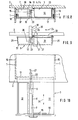
- the slider 20 is pulled against the cutting machine 7 by a spring 22. If the drawer 3 is pulled out of the cabinet body 1, the cutting machine 7 initially remains in a horizontal position, as shown in FIGS. 5 and 8. If, when the drawer 3 is pulled out further, the adjusting screw 21 reaches the front crossmember 17, the slide 20 stops. If you pull a short distance further on the handle of the drawer 3, the swivel axis 9 in the slot 19 rotates through 90 ° and with it the cutting machine 7. A tongue 23 of the swivel axis 9 enters the slot 19, which is correspondingly longer than the diameter of the swivel axis 9.
- the tongue 23 locks the cutting machine 7 correspondingly firmly when a pressure is exerted against the cutting blade 8 in the direction of the arrow 24. While the drawer 3 is fully extended and in the working position, as illustrated in Figures 6 and 10, the drawer 3 is supported by two rod-shaped supports 5 on the chassis 15 so that the cutting machine 7 is stationary even when pressure is exerted on the telescopic drawer 3 in the direction of arrow 26 becomes.
- the two supports 25 can be unlocked via a lever 27 by pulling an actuating tab 21, which is located below the drawer panel 30. Only after this unlocking is it possible to push the drawer 3 back into its closed position in the cabinet body. When inserted, the tongue 23 leaves the slot 19 and the cutting machine 7 returns to the horizontal storage position.
- a storage trough 32 for material to be cut is located inside the drawer 3 on the cutting blade side of the cutting machine 7, specifically below the cutting machine 7.
- the storage trough 32 is covered with a sliding lid 33, which consists, for example, of chrome steel.
- the sliding lid 33 has on the one hand the task A ufbewahrungswanne to seal 32, on the other hand also the function of a movable cutting plate.
- the material to be cut is placed on the sliding cover 33 as a cutting plate and moved back and forth in the direction of the arrow 34.
- a hand guard 35 can be attached to the sliding cover 33.
- the clippings fall via a chute 36 into a clippings container 37, which is located inside the drawer 3 on the side of the cutting machine 7 opposite the cutting blade side below it. Both the storage trough 32 and the cut container 37 can be removed from the drawer 3 for cleaning or as a serving bowl.
- the cutting is on machine 7 a (shown in dashed line) cutting plate 38 attached, which is pivoted against the cutting machine 7 with this out of the drawer and can then be folded out of the vertical position according to the direction of the arrow 39 into the horizontal position.
Landscapes
- Drawers Of Furniture (AREA)
Applications Claiming Priority (2)
| Application Number | Priority Date | Filing Date | Title |
|---|---|---|---|
| DE3108837 | 1981-03-09 | ||
| DE19813108837 DE3108837A1 (de) | 1981-03-09 | 1981-03-09 | "schneideinrichtung" |
Publications (2)
| Publication Number | Publication Date |
|---|---|
| EP0059964A2 true EP0059964A2 (fr) | 1982-09-15 |
| EP0059964A3 EP0059964A3 (fr) | 1984-05-16 |
Family
ID=6126692
Family Applications (1)
| Application Number | Title | Priority Date | Filing Date |
|---|---|---|---|
| EP82101778A Withdrawn EP0059964A3 (fr) | 1981-03-09 | 1982-03-06 | Dispositif à découper |
Country Status (2)
| Country | Link |
|---|---|
| EP (1) | EP0059964A3 (fr) |
| DE (1) | DE3108837A1 (fr) |
Cited By (1)
| Publication number | Priority date | Publication date | Assignee | Title |
|---|---|---|---|---|
| FR2561888A1 (fr) * | 1984-03-30 | 1985-10-04 | Prisca Ind | Nouvelle unite fonctionnelle escamotable recevant un appareil de petit electromenager pour cuisines par elements |
Families Citing this family (1)
| Publication number | Priority date | Publication date | Assignee | Title |
|---|---|---|---|---|
| DE102013001847A1 (de) * | 2013-02-04 | 2014-08-07 | Rudi Siller | Schneidmaschine für strangförmige Lebensmittel |
Family Cites Families (4)
| Publication number | Priority date | Publication date | Assignee | Title |
|---|---|---|---|---|
| DE1248877B (de) * | 1967-08-31 | Dehme über Bad Oeynhausen Gustav Kaiser | Befestigungs vorrichtung fur versenkbare Kuchen maschinen od dgl | |
| DE6751424U (de) * | 1968-08-14 | 1969-02-13 | Bauknecht Gmbh G | Schubladenkasten mit ein- und ausschwenkbarer arbeitsvorrichtung. |
| DE1932557A1 (de) * | 1969-06-27 | 1971-01-21 | Stumpp & Schuele Kg | Allesschneider mit Einbaueinrichtung |
| DE2408789A1 (de) * | 1974-02-23 | 1975-09-11 | Kurz Richard | Schwenkbeschlag |
-
1981
- 1981-03-09 DE DE19813108837 patent/DE3108837A1/de not_active Withdrawn
-
1982
- 1982-03-06 EP EP82101778A patent/EP0059964A3/fr not_active Withdrawn
Cited By (1)
| Publication number | Priority date | Publication date | Assignee | Title |
|---|---|---|---|---|
| FR2561888A1 (fr) * | 1984-03-30 | 1985-10-04 | Prisca Ind | Nouvelle unite fonctionnelle escamotable recevant un appareil de petit electromenager pour cuisines par elements |
Also Published As
| Publication number | Publication date |
|---|---|
| DE3108837A1 (de) | 1982-09-16 |
| EP0059964A3 (fr) | 1984-05-16 |
Similar Documents
| Publication | Publication Date | Title |
|---|---|---|
| EP2713816B1 (fr) | Ferrure de placard d'angle | |
| DE3942584A1 (de) | Einschiebe-falttuer-system fuer einen schrank | |
| EP3151718B1 (fr) | Machine à laver la vaisselle, en particulier machine à laver la vaisselle à usage ménager | |
| EP3066959A1 (fr) | Tiroir, element de meuble comprenant un tiroir et procede d'ouverture d'un tiroir | |
| EP3169215B1 (fr) | Lave-vaisselle domestique | |
| EP2713815A1 (fr) | Ferrure de placard d'angle | |
| DE102017211203B4 (de) | Hebesystem für eine Haushaltsgeschirrspülmaschine oder ein Möbel | |
| DE102011050823B4 (de) | Werkzeugbehälter | |
| DE3643033C1 (de) | Handtuchhalter | |
| EP1050246B1 (fr) | Placard | |
| DE10105847B4 (de) | Mitnahmevorrichtung für ausziehbaren Möbelboden | |
| DE8206325U1 (de) | Schneideeinrichtung | |
| DE212016000246U1 (de) | Schubladenwand | |
| EP1989953B1 (fr) | Armature pour une armoire angulaire dotée d'une étagère en une partie amovible | |
| DE3108837A1 (de) | "schneideinrichtung" | |
| WO2006131271A1 (fr) | Adaptateur pour module | |
| EP4245187A2 (fr) | Guide télescopique pour un élément de meuble mobile | |
| WO2020173812A2 (fr) | Panneau de commande pour une machine-outil | |
| DE8106629U1 (de) | "schneideinrichtung" | |
| AT522096B1 (de) | Anordnung mit wenigstens einer Schubladenausziehführung und mit wenigstens einer Verriegelungsvorrichtung zum lösbaren Verriegeln eines ausziehbaren Möbelteiles | |
| DE3119984C2 (fr) | ||
| DE2156740C3 (de) | Schrankauszug mit eingebauter Schneidemaschine | |
| DE202010004097U1 (de) | Schiebewand | |
| DE8710583U1 (de) | Arbeitstisch | |
| EP1946673A1 (fr) | Extracteur pour le logement d'un système de récipient destiné à l'utilisation dans un élément d'armoire d'un dispositif de meuble |
Legal Events
| Date | Code | Title | Description |
|---|---|---|---|
| PUAI | Public reference made under article 153(3) epc to a published international application that has entered the european phase |
Free format text: ORIGINAL CODE: 0009012 |
|
| AK | Designated contracting states |
Designated state(s): AT BE CH DE FR GB IT LU NL SE |
|
| 17P | Request for examination filed |
Effective date: 19830312 |
|
| PUAL | Search report despatched |
Free format text: ORIGINAL CODE: 0009013 |
|
| AK | Designated contracting states |
Designated state(s): AT BE CH DE FR GB IT LI LU NL SE |
|
| STAA | Information on the status of an ep patent application or granted ep patent |
Free format text: STATUS: THE APPLICATION IS DEEMED TO BE WITHDRAWN |
|
| 18D | Application deemed to be withdrawn |
Effective date: 19851001 |
|
| RIN1 | Information on inventor provided before grant (corrected) |
Inventor name: ANSCHUETZ, THEO |