EP0059981B1 - Dispositif pour positionner automatiquement une bande de matériau - Google Patents
Dispositif pour positionner automatiquement une bande de matériau Download PDFInfo
- Publication number
- EP0059981B1 EP0059981B1 EP82101906A EP82101906A EP0059981B1 EP 0059981 B1 EP0059981 B1 EP 0059981B1 EP 82101906 A EP82101906 A EP 82101906A EP 82101906 A EP82101906 A EP 82101906A EP 0059981 B1 EP0059981 B1 EP 0059981B1
- Authority
- EP
- European Patent Office
- Prior art keywords
- splicing
- sheets
- sheet
- forms
- advancing
- Prior art date
- Legal status (The legal status is an assumption and is not a legal conclusion. Google has not performed a legal analysis and makes no representation as to the accuracy of the status listed.)
- Expired
Links
Images


Classifications
-
- B—PERFORMING OPERATIONS; TRANSPORTING
- B65—CONVEYING; PACKING; STORING; HANDLING THIN OR FILAMENTARY MATERIAL
- B65H—HANDLING THIN OR FILAMENTARY MATERIAL, e.g. SHEETS, WEBS, CABLES
- B65H21/00—Apparatus for splicing webs
-
- B—PERFORMING OPERATIONS; TRANSPORTING
- B65—CONVEYING; PACKING; STORING; HANDLING THIN OR FILAMENTARY MATERIAL
- B65H—HANDLING THIN OR FILAMENTARY MATERIAL, e.g. SHEETS, WEBS, CABLES
- B65H20/00—Advancing webs
- B65H20/20—Advancing webs by web-penetrating means, e.g. pins
Definitions
- the present invention relates to a device for the automatic advance of sheets or forms.
- a device for the automatic advance of sheets or forms is known from US-A-3 477 626.
- US-A-3 477 626 discloses a double tractor arrangement for automatic advance of sheets.
- intermittent sheet advance there is no suggestion in this document of intermittent sheet advance and no suggestion that the sheet advancing mechanism disclosed could be used for accurate positioning of sheets at a predetermined location.
- An object of the present invention is to provide a device for automatic advance of each form to a predetermined position on a surface in order to reduce dead times further.
- the device comprises movable means positionable to form an inlet opening and an exit opening for a single sheet or form, said means being movable between an operating position, in which said openings are delimited, and a non-operating position in which the inside of the positioning device is accessible, and the form or sheet possibly contained therein can be freely removed, and sheet or form advancing means having members for engagement with and dragging of the form characterized in that means is provided upstream of said advancing means for the initial positioning of the form or sheet with respect to said advancing means, in that a splicing plane is provided for splicing of said sheets or forms, in that said exit opening is aligned and substantially coplanar with the surface of said splicing plane, and in that said advancing means is actuated intermittently to advance the sheets or forms for an adjustable and predetermined distance to position the sheets or forms on said splicing plane.
- said cover plate is hinged with respect to the casing, the latter being of the box type, and said advancing means consist of a pair of conveying-belts, from the outer surfaces of which pins of teeth protrude engaging the holes normally provided along the opposed longitudinal edges of the sheets or forms, said conveying belt being actuated for an intermittent advance.
- two said advancing devices are provided and are disposed in opposed relationship to advance respective sheets or forms to respective splicing half planes disposed in closely adjacent relationship for splicing together of said sheets or forms.
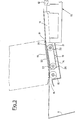
- the reference 10 generally indicates a splicing plane comprising two half planes 11 and 12, movable between a splicing position, and a position of preliminary approaching of the forms to be spliced.
- the sheet of forms 1 to be positioned onto the related half plane 11, has the usual holes provided for the use in electroaccounting and data processing machines.
- the device of the present invention comprising a generally parallelepiped casing 14, having a closure or cover plate 15, hinged to the casing 14 along a longitudinal edge, so as to be movable between a closed or operating position, shown in solid lines in Figs. 1 and 3, and an open or upwardly turned position (shown in chain dot lines in Figs. 1 and 3).
- the plate 15 In the closed position of the plate 15, it forms with the fore and aft vertical walls of the casing 14 a slit 16 for the inlet of the form and a slit 17 for the exit of the form.
- a friction roller 18 is provided, capable of interfering in a predetermined manner with the pattern of the form or sheet and engaging it for the positioning thereof with respect to the advancing means to be hereinafter described. It is evident that, instead of the friction roller 18, wheels having the same function and spaced from each other can be used.
- a pair of conveying belts is provided, having pins or teeth 20, protruding from their outer surface and positioned so as to correspond with the holes 13 of the form or sheet 1.
- the conveying belts 19 are driven by pairs of rollers 21 and 22, one of which is the driving roller and the other is a transmission roller, in the usual manner, for instance by means of an electric motor of the stepping type. It is evident at this point that the exact positioning of the sheet or form 1 onto the respective splicing half table 11, becomes only a matter of fine adjustment of the advancing motion of the conveying belts 19, furthermore permitting the elimination of the form or sheet positioning pins or teeth of the splicing half table.
- vertical members may be provided to make easier the introduction of the form or sheet in the inlet slit. It is furthermore clear that by the device of the present invention there is fully eliminated the dead time for the manual exact positioning of the form or sheet onto the respective half table since the possible manual operation consists only in the introduction of the form or sheet in the inlet slit 16.
- automatic means controlled by the splicing apparatus and sequentially connected to the operating cycle thereof, adapted to control the displacement of the cover plate 15 between the said two operating positions thereof, said automatic means for instance comprising a pneumatic piston actuated to upwardly turn over the plate 15, when the splicing operation is completed and the splicing plane 10 is lowered to set free the spliced forms.
- the forms to be spliced are respectively the first and the last form of two form packages
- arms having sucking cups of a per se known type, to transfer the two forms to be spliced to the inlet slits of the two positioning devices serving the two half planes 11 and 12.
Landscapes
- Replacement Of Web Rolls (AREA)
- Registering Or Overturning Sheets (AREA)
- Registering, Tensioning, Guiding Webs, And Rollers Therefor (AREA)
- Controlling Sheets Or Webs (AREA)
- Sewing Machines And Sewing (AREA)
Claims (5)
Priority Applications (1)
| Application Number | Priority Date | Filing Date | Title |
|---|---|---|---|
| AT82101906T ATE15786T1 (de) | 1981-03-10 | 1982-03-10 | Vorrichtung zum selbsttaetigen positionieren einer materialbahn. |
Applications Claiming Priority (2)
| Application Number | Priority Date | Filing Date | Title |
|---|---|---|---|
| IT2103381U | 1981-03-10 | ||
| ITMI1981U21033U IT8121033U1 (it) | 1981-03-10 | 1981-03-10 | Dispositivo per il posizionamento automatico di strisce di materiale in foglio |
Publications (2)
| Publication Number | Publication Date |
|---|---|
| EP0059981A1 EP0059981A1 (fr) | 1982-09-15 |
| EP0059981B1 true EP0059981B1 (fr) | 1985-09-25 |
Family
ID=11175690
Family Applications (1)
| Application Number | Title | Priority Date | Filing Date |
|---|---|---|---|
| EP82101906A Expired EP0059981B1 (fr) | 1981-03-10 | 1982-03-10 | Dispositif pour positionner automatiquement une bande de matériau |
Country Status (9)
| Country | Link |
|---|---|
| US (1) | US4491259A (fr) |
| EP (1) | EP0059981B1 (fr) |
| JP (1) | JPS57209151A (fr) |
| AT (1) | ATE15786T1 (fr) |
| BE (1) | BE892446A (fr) |
| CH (1) | CH651527A5 (fr) |
| DE (1) | DE3266473D1 (fr) |
| FR (1) | FR2503111B1 (fr) |
| IT (1) | IT8121033U1 (fr) |
Families Citing this family (3)
| Publication number | Priority date | Publication date | Assignee | Title |
|---|---|---|---|---|
| DE3328255A1 (de) * | 1983-08-04 | 1985-02-21 | Siemens AG, 1000 Berlin und 8000 München | Klebestation fuer einen schnelldrucker |
| US5037078A (en) * | 1988-04-05 | 1991-08-06 | K.K. Sankyo Seiki Seisakusho | Method of controlling an automatic sheet connecting and feeding apparatus |
| US6029728A (en) * | 1996-12-20 | 2000-02-29 | Hetem; James | Continuous flow device for computer printer invoices |
Family Cites Families (7)
| Publication number | Priority date | Publication date | Assignee | Title |
|---|---|---|---|---|
| CA686603A (en) * | 1964-05-19 | Richard A. Butler, Jr. | Web splicing machine | |
| GB256944A (en) * | 1925-08-17 | 1927-07-14 | Lawrence Carr Steele | Improvements in or relating to mechanisms for removing sheets from a pack |
| US3169896A (en) * | 1962-08-17 | 1965-02-16 | Dresser Products Inc | Tape splicer |
| DE1524445B2 (de) * | 1966-12-24 | 1973-02-15 | IBM Deutschland, 7000 Stuttgart | Vorrichtung zum voneinander unabhaengigen transportieren von zwei papierbahnen |
| DE2219826C3 (de) * | 1972-04-22 | 1982-03-04 | Agfa-Gevaert Ag, 5090 Leverkusen | Klebevorrichtung zum Verbinden zweier Bahnenden |
| JPS5056908A (fr) * | 1973-09-14 | 1975-05-19 | ||
| US4226353A (en) * | 1979-07-25 | 1980-10-07 | International Business Machines Corporation | Forms feed tractor |
-
1981
- 1981-03-10 IT ITMI1981U21033U patent/IT8121033U1/it unknown
-
1982
- 1982-03-09 US US06/356,333 patent/US4491259A/en not_active Expired - Fee Related
- 1982-03-09 CH CH1435/82A patent/CH651527A5/it not_active IP Right Cessation
- 1982-03-10 FR FR8204016A patent/FR2503111B1/fr not_active Expired
- 1982-03-10 EP EP82101906A patent/EP0059981B1/fr not_active Expired
- 1982-03-10 DE DE8282101906T patent/DE3266473D1/de not_active Expired
- 1982-03-10 JP JP57037897A patent/JPS57209151A/ja active Pending
- 1982-03-10 BE BE0/207531A patent/BE892446A/fr not_active IP Right Cessation
- 1982-03-10 AT AT82101906T patent/ATE15786T1/de not_active IP Right Cessation
Also Published As
| Publication number | Publication date |
|---|---|
| IT8121033V0 (it) | 1981-03-10 |
| DE3266473D1 (en) | 1985-10-31 |
| EP0059981A1 (fr) | 1982-09-15 |
| FR2503111A1 (fr) | 1982-10-08 |
| CH651527A5 (it) | 1985-09-30 |
| IT8121033U1 (it) | 1982-09-10 |
| ATE15786T1 (de) | 1985-10-15 |
| BE892446A (fr) | 1982-07-01 |
| JPS57209151A (en) | 1982-12-22 |
| FR2503111B1 (fr) | 1986-02-28 |
| US4491259A (en) | 1985-01-01 |
Similar Documents
| Publication | Publication Date | Title |
|---|---|---|
| US5267933A (en) | Folding machine, particularly for signatures | |
| US4782987A (en) | Method for the feeding of a material web | |
| US5029828A (en) | Continuous paper folding device for a printing apparatus | |
| US5618375A (en) | Envelope processing unit | |
| US4304345A (en) | Modular bidirectional tractor feed assembly | |
| US4363478A (en) | Method and apparatus of feeding corrugated boards | |
| SE458998B (sv) | Apparat foer anbringning av spaennband | |
| JPH0327798Y2 (fr) | ||
| JP3803896B2 (ja) | 包装装置 | |
| US3578138A (en) | Paper adjusting mechanism | |
| EP0059981A1 (fr) | Dispositif pour positionner automatiquement une bande de matériau | |
| JPS5818282A (ja) | 送りカタピラで移動される記録担体の引張り装置 | |
| JP3368992B2 (ja) | 写真フイルムの穿孔及び切断装置 | |
| JPH0374370B2 (fr) | ||
| EP0183982B1 (fr) | Appareil d'accommodation de papier photographique | |
| EP0757962B1 (fr) | Système pour réalimenter par aspiration des feuilles, en particulier des feuilles en carton ondulé, à utiliser dans des machines d'impression et de découpage à l'emporte-pièce | |
| US4634268A (en) | Print mask apparatus | |
| US4518381A (en) | Sheet folding machine | |
| EP0089684B1 (fr) | Dispositif pour relier plusieurs bandes avec des rubans de blocage | |
| JPS59209166A (ja) | 印字装置 | |
| JPS62231779A (ja) | 連続用紙の紙送り機構 | |
| EP0296360A2 (fr) | Appareil de pliage | |
| CN220664280U (zh) | 一种带导向装置的瓦楞纸印刷机 | |
| JP3026977B2 (ja) | 感光体シートの搬送装置 | |
| JP2823668B2 (ja) | 排紙装置 |
Legal Events
| Date | Code | Title | Description |
|---|---|---|---|
| PUAI | Public reference made under article 153(3) epc to a published international application that has entered the european phase |
Free format text: ORIGINAL CODE: 0009012 |
|
| AK | Designated contracting states |
Designated state(s): AT DE GB IT LU NL |
|
| 17P | Request for examination filed |
Effective date: 19830314 |
|
| GRAA | (expected) grant |
Free format text: ORIGINAL CODE: 0009210 |
|
| RAP1 | Party data changed (applicant data changed or rights of an application transferred) |
Owner name: INDUSTRIA GRAFICA MESCHI S.R.L. |
|
| AK | Designated contracting states |
Designated state(s): AT DE GB IT LU NL |
|
| PG25 | Lapsed in a contracting state [announced via postgrant information from national office to epo] |
Ref country code: NL Effective date: 19850925 Ref country code: IT Free format text: LAPSE BECAUSE OF FAILURE TO SUBMIT A TRANSLATION OF THE DESCRIPTION OR TO PAY THE FEE WITHIN THE PRESCRIBED TIME-LIMIT;WARNING: LAPSES OF ITALIAN PATENTS WITH EFFECTIVE DATE BEFORE 2007 MAY HAVE OCCURRED AT ANY TIME BEFORE 2007. THE CORRECT EFFECTIVE DATE MAY BE DIFFERENT FROM THE ONE RECORDED. Effective date: 19850925 Ref country code: AT Effective date: 19850925 |
|
| REF | Corresponds to: |
Ref document number: 15786 Country of ref document: AT Date of ref document: 19851015 Kind code of ref document: T |
|
| REF | Corresponds to: |
Ref document number: 3266473 Country of ref document: DE Date of ref document: 19851031 |
|
| NLV1 | Nl: lapsed or annulled due to failure to fulfill the requirements of art. 29p and 29m of the patents act | ||
| PG25 | Lapsed in a contracting state [announced via postgrant information from national office to epo] |
Ref country code: LU Free format text: LAPSE BECAUSE OF NON-PAYMENT OF DUE FEES Effective date: 19860331 |
|
| PLBE | No opposition filed within time limit |
Free format text: ORIGINAL CODE: 0009261 |
|
| STAA | Information on the status of an ep patent application or granted ep patent |
Free format text: STATUS: NO OPPOSITION FILED WITHIN TIME LIMIT |
|
| 26N | No opposition filed | ||
| PGFP | Annual fee paid to national office [announced via postgrant information from national office to epo] |
Ref country code: GB Payment date: 19910311 Year of fee payment: 10 |
|
| PGFP | Annual fee paid to national office [announced via postgrant information from national office to epo] |
Ref country code: DE Payment date: 19910327 Year of fee payment: 10 |
|
| PG25 | Lapsed in a contracting state [announced via postgrant information from national office to epo] |
Ref country code: GB Effective date: 19920310 |
|
| GBPC | Gb: european patent ceased through non-payment of renewal fee | ||
| PG25 | Lapsed in a contracting state [announced via postgrant information from national office to epo] |
Ref country code: DE Effective date: 19921201 |