EP0060007A1 - Dispositif de fixation pour éléments de façade à une structure de support - Google Patents
Dispositif de fixation pour éléments de façade à une structure de support Download PDFInfo
- Publication number
- EP0060007A1 EP0060007A1 EP82200284A EP82200284A EP0060007A1 EP 0060007 A1 EP0060007 A1 EP 0060007A1 EP 82200284 A EP82200284 A EP 82200284A EP 82200284 A EP82200284 A EP 82200284A EP 0060007 A1 EP0060007 A1 EP 0060007A1
- Authority
- EP
- European Patent Office
- Prior art keywords
- wall
- wall panels
- support structure
- assembly according
- bracket
- Prior art date
- Legal status (The legal status is an assumption and is not a legal conclusion. Google has not performed a legal analysis and makes no representation as to the accuracy of the status listed.)
- Granted
Links
- 238000000034 method Methods 0.000 claims abstract description 7
- 238000007789 sealing Methods 0.000 claims description 20
- 239000006260 foam Substances 0.000 claims description 14
- 239000000945 filler Substances 0.000 claims description 3
- 239000002184 metal Substances 0.000 claims description 2
- 210000001364 upper extremity Anatomy 0.000 claims description 2
- 239000004567 concrete Substances 0.000 description 2
- 230000008602 contraction Effects 0.000 description 2
- 239000011211 glass fiber reinforced concrete Substances 0.000 description 2
- 229920000915 polyvinyl chloride Polymers 0.000 description 2
- 239000004800 polyvinyl chloride Substances 0.000 description 2
- XLYOFNOQVPJJNP-UHFFFAOYSA-N water Substances O XLYOFNOQVPJJNP-UHFFFAOYSA-N 0.000 description 2
- 229910000831 Steel Inorganic materials 0.000 description 1
- 230000006835 compression Effects 0.000 description 1
- 238000007906 compression Methods 0.000 description 1
- 230000000694 effects Effects 0.000 description 1
- 239000003822 epoxy resin Substances 0.000 description 1
- 206010016256 fatigue Diseases 0.000 description 1
- 230000001771 impaired effect Effects 0.000 description 1
- 239000013521 mastic Substances 0.000 description 1
- 239000000463 material Substances 0.000 description 1
- 238000012986 modification Methods 0.000 description 1
- 230000004048 modification Effects 0.000 description 1
- 229920000647 polyepoxide Polymers 0.000 description 1
- 239000011495 polyisocyanurate Substances 0.000 description 1
- 239000010959 steel Substances 0.000 description 1
Images
Classifications
-
- E—FIXED CONSTRUCTIONS
- E04—BUILDING
- E04F—FINISHING WORK ON BUILDINGS, e.g. STAIRS, FLOORS
- E04F13/00—Coverings or linings, e.g. for walls or ceilings
- E04F13/07—Coverings or linings, e.g. for walls or ceilings composed of covering or lining elements; Sub-structures therefor; Fastening means therefor
- E04F13/08—Coverings or linings, e.g. for walls or ceilings composed of covering or lining elements; Sub-structures therefor; Fastening means therefor composed of a plurality of similar covering or lining elements
- E04F13/0889—Coverings or linings, e.g. for walls or ceilings composed of covering or lining elements; Sub-structures therefor; Fastening means therefor composed of a plurality of similar covering or lining elements characterised by the joints between neighbouring elements, e.g. with joint fillings or with tongue and groove connections
-
- E—FIXED CONSTRUCTIONS
- E04—BUILDING
- E04F—FINISHING WORK ON BUILDINGS, e.g. STAIRS, FLOORS
- E04F13/00—Coverings or linings, e.g. for walls or ceilings
- E04F13/07—Coverings or linings, e.g. for walls or ceilings composed of covering or lining elements; Sub-structures therefor; Fastening means therefor
- E04F13/08—Coverings or linings, e.g. for walls or ceilings composed of covering or lining elements; Sub-structures therefor; Fastening means therefor composed of a plurality of similar covering or lining elements
- E04F13/0801—Separate fastening elements
- E04F13/0803—Separate fastening elements with load-supporting elongated furring elements between wall and covering elements
- E04F13/081—Separate fastening elements with load-supporting elongated furring elements between wall and covering elements with additional fastening elements between furring elements and covering elements
- E04F13/0814—Separate fastening elements with load-supporting elongated furring elements between wall and covering elements with additional fastening elements between furring elements and covering elements fixed by means of clamping action
-
- E—FIXED CONSTRUCTIONS
- E04—BUILDING
- E04F—FINISHING WORK ON BUILDINGS, e.g. STAIRS, FLOORS
- E04F19/00—Other details of constructional parts for finishing work on buildings
- E04F19/02—Borders; Finishing strips, e.g. beadings; Light coves
- E04F19/06—Borders; Finishing strips, e.g. beadings; Light coves specially designed for securing panels or masking the edges of wall- or floor-covering elements
Definitions
- the invention relates to an assembly for fixing wall panels to a rearwardly positioned support structure, including a plurality of support rails having their longitudinal extent directed perpendicularly to that of the wall panels, and to a method for fixing wall panels to such support structure by means of this assembly.
- frog plates are pressed with one end to a flange of a support rail and with the other end to the rear face of the respective wall panel in order to establish a connection under employment of considerable force by means of bolts passing through the wall panels.
- This manner of fixing has the disadvantage that the frog plates can deflect the rear face of the wall panels and even serious damages of the rear face of the wall panels can be caused due to differences in expansion and contraction, respectively, between the wall panels and the frog plates. Also, there is a danger that the frog plates will deflect by the great forces applied thereto, whereby the fixation of the wall panels to the support structure is impaired.
- a further disadvantage is that there are practically no possibilities for adjusting the frog plates, so that the holes in the wall panels for the passage of the bolts have to be drilled with great accuracy on the building site.
- the invention has the object of providing an assembly of the kind indicated above, which has been designed to efficiently remove the said disadvantages and to obtain a better fixation of the wall panels to the rearwardly positioned support structure.
- the assembly according to the invention is characterized by a jointing strip having substantially the same length as the wall panels and including a front wall and two wall portions of substantially U-shaped cross-section, said wall portions being disposed behind the front wall, said wall portions being spaced from each other and oppositely directed with respect to each other, said wall portions being adapted for receiving projecting front edge portions of adjacent wall panels so as to form an intermediate joint between said wall panels; by a plurality of short fixing clamps slidably disposed in the jointing strip and including a hole; by a bolt for each fixing clamp, said bolt having a nut cooperating therewith, said bolt being adapted to be inserted through the hole in the fixing clamp, said bolt being dimensioned so as to traverse the joint between the adjacent wall panels; and by a bracket for each of said bolts, said bracket having an eye for the passage of the bolt, said bracket being adapted to be connected to a support rail of the support structure.
- the fixing assembly extending through the joint between adjacent wall panels does no longer contact the rear face of the wall panels, so that there is no longer any danger of damaging this rear face.
- connection between adjacent panels should be such as to prevent rearward ingression of humidity and water vapour.
- a preferred embodiment of the assembly according to the invention is characterized by elastic sealing gaskets of rubber or the like, said gaskets having substantially the same length as the wall panels and being adapted to be clamped between the jointing strip and the front side of the adjacent wall panels.
- the invention further relates to a jointing strip, a fixing clamp and a bracket, adapted for use with the assembly according to the invention.
- the invention further relates to a wall panel formed as a sandwich panel and comprising a front skin, a rear skin and an intermediate synthetic foam layer, adapted to be fixed to a rearwardly positioned support structure including a plurality of support rails having their longitudinal extent directed perpendicularly to that of the wall panel, by means of the assembly described hereinbefore.
- This wall panel according to the invention is characterized in that two opposite edges of the front skin project with respect to the synthetic foam layer.
- a recess in the synthetic foam layer may be formed behind both projecting edges of the front skin.
- the projecting edges of the front skin may constitute the ends of rearwardly off-set edge portions which are smoothly finished at the front side.
- the invention finally relates to a method for fixing wall panels to a rearwardly positioned support structure including a plurality of support rails having their longitudinal extent directed perpendicularly to that of the wall panels, by using the assembly described hereinbefore.
- This method according to the invention is characterized in that a jointing strip is put together with a number of fixing clamps corresponding with the number of support rails of the support structure and with the associated bolts and the brackets, and thereafter the jointing strip is disposed with one of its substantially U-shaped wall portions on a projecting front edge portion of a wall panel which bears with its rear side against the support rails of the support structure, and the brackets are engaged with the support rails of the support structure, and thereafter a successive wall panel with a projecting front edge portion is inserted in the other, substantially U-shaped wall portion of the said jointing strip and with its rear side is positioned against the support rails of the support structure, and subsequently the nuts of the bolts are tightened from the rear side.
- the elastic sealing gaskets may be clamped between the jointing strip and the front side of the wall adjacent wall panels.
- a fitting filler mass may be disposed in the joint between the adjacent wall panels.
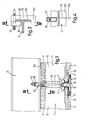
- Fig. 1 shows the fixation of two adjacent upright wall panels 1 to a rearwardly positioned support structure generally consisting in a simple steel framework and including, in the embodiment illustrated in the drawing, a plurality of horizontal support rails 2.
- These wall panels 1 according to fig. 1 are made as. sandwich panels consisting of a front skin 3 and a rear skin 4 with a synthetic foam layer 5 interposed therebetween.
- the front skin 3 for example, can be made of glass- fibre reinforced concrete finished with washed-out gravel, polyvinylchloride or the like.
- the rear skin 4 for example, can be made of glass- fibre reinforced concrete finished with polyvinylchloride, epoxy resin or the like.
- the intermediate synthetic foam layer 5 may consist of P.I.R. foam (Poly-isocyanurate foam) or the like.
- the wall panels 1 extend along the entire height of the building so as to avoid horizontal joints.
- both side edges 6 of the front skin 3 of each wall panel 1 project with respect to the synthetic foam layer 5, since behind each of both projecting side edges 6 of the front skin 3 an upright recess 7 extending along the entire height has been formed in the synthetic foam layer 5 .
- both projecting side edges 6 of the front skin 3 of each wall panel 1 constitute the ends of edge portions 8 of the front skin 3, said edge portions 8 at the front side being smoothly finished and being rearwardly off-set.along the entire height.
- a jointing strip 9 having substantially the same height as the wall panels 1.
- the fixing assembly of the invention includes a plurality of short fixing clamps 10 adapted to be slidably received in the jointing strip 9, said clamps including a hole 11. Through this hole 11 a bolt 13 can be passed cooperating with a nut 12, the bolt 13 being dimensioned so as to traverse the joint 14 between the adjacent wall panels 1.
- Each bolt 13 can mount a bracket 15 including an eye 16 adapted for the passage of the bolt 13, the bracket 15 being adapted to be connected to a horizontal support rail 2 of the support structure.
- the embodiment illustrated in the drawing shows the use of elastic sealing gaskets 17 made of rubber or similar material and having substantially the same height as the wall panels 1 and being adapted to be clamped between the jointing strip 9 and the front side of the adjacent wall panels 1.
- the jointing strip 9 includes a front wall 18 and, positioned rearwardly thereof, two wall portions 19 of substantially U-shaped cross-section, said wall portions 19 being spaced from each other and oppositely directed with respect to each other, said wall portions 19 receiving the projecting upright side edges 6 of the front skins 5 of the adjacent wall panels 1, an intermediate joint 14 being left clear between these wall panels 1.
- Both front entry wall portions 20 each are connected to the front wall 18 of the jointing strip 9 by means of a lateral confining wall portion 22 extending parallel to the front wall 18 and of the respective side edge 23 extending perpendicularly thereto.
- Each confining wall portion 22 in the embodiment illustrated in the drawing serves as the front confinement of the respective elastic sealing gasket 17 and includes an undercut 24 for retaining the respective elastic sealing gasket 17.
- the rear confinement of the elastic sealing gaskets 17 is effected by the smoothly finished front side of the rearwardly off-set edge portions 8 of the front skin 3 of the wall panels 1.
- the elastic sealing gaskets 17 it is also possible to fill-up the respective spaces between the jointing strip 9 and the front side of the adjacent wall panels 1 by injecting a flexible sealing mass, for example, mastic or a synthetic foam mass.
- a flexible sealing mass for example, mastic or a synthetic foam mass.
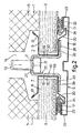
- the short fixing clamps 10 which are slidable in the jointing strip 9, are, in the embodiment illustrated in the drawing, omega profiles including a central wall portion 25 of U-shaped cross-section, a perpendicularly bent, laterally extending end edge 26 joining said wall portion 25 at either side. In the web 27 of the U-shaped wall portion 25 a hole 11 is formed.
- the U-shaped wall portion 25 of the fixing clamp 10 thus extends with minimum clearance rearwardly between the webs 30 of the U-shaped wall portions 19 of the jointing strip 9.
- each bolt 13 which is inserted through the hole 11 in the web 27 of the fixing clamp 10, is locked against rotation by being received in the U-shaped wall portion 25 of the cooperating fixing clamp 10.
- Each bracket 15 has a slot 32, which is hooked over an upright flange 33 of a support rail 2 of the support structure. Furthermore, each bracket 15 is formed with an abutment edge 34 extending perpendicularly to the slot 32 and adapted to fittingly engage under the upright flange 33 of the respective support rail 2 of the support structure.
- Each bracket 15 is made of sheet metal and its eye 16 has an elongated shape and bounds the slot 32 at one side.
- the described embodiment of the bracket 15 has the advantage that by reason of the abutment edge3the bracket 15 can never loosen itself from the upright flange 33 of the support rail 2 of the support structure.
- this bracket 15 is disposed in the joint 14 between the adjacent wall panels 1 , so that the bracket 15 projects rearwardly only over a small length.
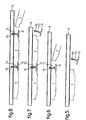
- Figs. 5 - 8 illustrate the manner of assembling the successive wall panels 1.
- a jointing strip 9 is mounted by means of the wall portion 19 which is substantially U-shaped in cross-section and is disposed on the respective side (fig. 5). This is simplified by the entry wall portion 20 and the entry end edge 21.
- the jointing strip 9 have already been disposed a number of short fixing clamps 10 corresponding with the number of support rails 2 of the support structure, each fixing clamp 10 including a bolt 13 cooperating with a nut 12 and a bracket-15 as very schematically indicated in fig. 5.
- each bracket 15 already will be positioned to bear on the cooperating support rail 2 of the support structure, whereby the upper portion of the upright flange 33 of the respective support rail 2 will be partly received in the slot 32 of the bracket 15 and the abutment edge 34 of the bracket 15 will engage under the lower portion of the upright flange 33.
- the successive wall panel 1 is mounted so as to bear on a masonry or concrete base and to be inserted in that U-shaped wall portion 19 of the jointing strip 9, which is directed to the respective side (fig. 6).
- the elastic sealing gaskets 17 can be mounted between the jointing strips 9 and the rearwardly off-set edge portions 8 of the adjacent wall panels 1.
- the joints 14 between the successive wall panels 1 finally can be filled with a filler mass.
- the horizontal, inwardly directed forces exercised on the wall panels 1, for example due to wind pressure, are taken up by the support rails 2 of the support structure.
- the horizontal, outwardly directed forces exercised on the wall panels 1, for example by wind suction, are transmitted by the front skins 3 of the wall panels 1 through the jointing strips 9 to the fixing clamps 10 and therefrom through the bolts 13 and the brackets 15 to the support rails 2 of the support structure.
- the intermediate synthetic foam layer 5 never is directly loaded on tension.
- the invention provides a fixing assembly which has the important advantage that the rear face of the wall panels 1 is not at all loaded.
- wall panels 1 extend vertically and the support rails 2 of the support structure extend horizontally, it is of course, also possible to use horizontal wall panels 1 and in that case the support rails 2 of the rearwardly positioned support structure will extend vertically.
Landscapes
- Engineering & Computer Science (AREA)
- Architecture (AREA)
- Civil Engineering (AREA)
- Structural Engineering (AREA)
- Finishing Walls (AREA)
- Connection Or Junction Boxes (AREA)
- Load-Bearing And Curtain Walls (AREA)
Priority Applications (1)
| Application Number | Priority Date | Filing Date | Title |
|---|---|---|---|
| AT82200284T ATE13923T1 (de) | 1981-03-09 | 1982-03-05 | Vorrichtung zum befestigen von fassadenplatten an einer unterkonstruktion. |
Applications Claiming Priority (2)
| Application Number | Priority Date | Filing Date | Title |
|---|---|---|---|
| NL8101131A NL8101131A (nl) | 1981-03-09 | 1981-03-09 | Inrichting voor het bevestigen van gevelpanelen aan een achterliggende draagconstructie. |
| NL8101131 | 1981-03-09 |
Publications (2)
| Publication Number | Publication Date |
|---|---|
| EP0060007A1 true EP0060007A1 (fr) | 1982-09-15 |
| EP0060007B1 EP0060007B1 (fr) | 1985-06-19 |
Family
ID=19837131
Family Applications (1)
| Application Number | Title | Priority Date | Filing Date |
|---|---|---|---|
| EP82200284A Expired EP0060007B1 (fr) | 1981-03-09 | 1982-03-05 | Dispositif de fixation pour éléments de façade à une structure de support |
Country Status (7)
| Country | Link |
|---|---|
| US (1) | US4475325A (fr) |
| EP (1) | EP0060007B1 (fr) |
| JP (1) | JPS57161245A (fr) |
| AT (1) | ATE13923T1 (fr) |
| DE (1) | DE3264195D1 (fr) |
| NL (1) | NL8101131A (fr) |
| ZA (1) | ZA821452B (fr) |
Cited By (7)
| Publication number | Priority date | Publication date | Assignee | Title |
|---|---|---|---|---|
| GB2206909A (en) * | 1987-07-13 | 1989-01-18 | Issac Blacker | Cladding panels fixed to rails on floor rafts |
| GB2207931A (en) * | 1987-08-13 | 1989-02-15 | Stephen Leslie Rose | Building cladding panels clamped by internally operated means |
| EP0434647A3 (en) * | 1989-12-22 | 1991-12-04 | Gn/Pi Di L. Granieri & Figli S.N.C. | Modular sectional construction for the fronts of buildings and/or for insulation coatings of current masonries |
| FR2754842A1 (fr) * | 1996-10-18 | 1998-04-24 | Tecnopan | Dispositif de revetement interieur de locaux, en particulier destines a un usage de laboratoires ou de locaux de production et de stockage dans l'industrie agro-alimentaire ou de salles blanches |
| WO2000012836A3 (fr) * | 1998-09-01 | 2000-06-02 | Hwee Hin Lim | Systeme a mur-rideau |
| RU2272879C2 (ru) * | 2004-02-17 | 2006-03-27 | Благодарная Елена Михайловна | Узел крепления составных облицовочных конструкций |
| AT13103U1 (de) * | 2012-04-27 | 2013-06-15 | Habau Hoch Und Tiefbaugesellschaft M B H | Vorrichtung zum Befestigen von Betonplatten |
Families Citing this family (14)
| Publication number | Priority date | Publication date | Assignee | Title |
|---|---|---|---|---|
| IT1221850B (it) * | 1987-08-07 | 1990-07-12 | Col Diego Da | Sistema di rivestimento a specchiature formantifacciata continua per edifici |
| SE468606B (sv) * | 1991-09-24 | 1993-02-15 | Nils Gunnar Jansson | Foerfarande jaemte anordning foer saekrande av fasadelement av glas |
| CA2193030A1 (fr) * | 1996-12-16 | 1998-06-16 | Gerald Robinson | Systeme de construction |
| GB2373323B (en) * | 2001-03-14 | 2005-04-13 | Greenwood Air Man Ltd | A vent device |
| US6571523B2 (en) | 2001-05-16 | 2003-06-03 | Brian Wayne Chambers | Wall framing system |
| FR2841289B1 (fr) * | 2002-06-19 | 2005-12-23 | Saint Gobain | Systeme de fixation d'un panneau de materiau fragile |
| US6871822B2 (en) * | 2003-04-18 | 2005-03-29 | The Boeing Company | Apparatus and methods of attaching panels to support structures |
| US20050217194A1 (en) * | 2004-03-30 | 2005-10-06 | Eric Krantz-Lilienthal | Trim system for a suspended ceiling |
| US7810294B2 (en) * | 2004-09-29 | 2010-10-12 | Ig Creative Solutions, Inc. | Housing construction system |
| US7849651B2 (en) * | 2005-05-31 | 2010-12-14 | Kubota Matsushitadenko Exterior Works, Ltd. | Wall materials bracket and insulating wall structure |
| US7937903B2 (en) * | 2007-03-07 | 2011-05-10 | Portafab | Panelized ceiling system |
| WO2012050554A1 (fr) | 2010-10-11 | 2012-04-19 | Ig Creative Solutions, Inc. | Système de construction de maison |
| JP6052539B2 (ja) * | 2012-12-10 | 2016-12-27 | 清水建設株式会社 | 下地材への内装板材取付構造 |
| US20240287813A1 (en) * | 2023-02-23 | 2024-08-29 | Advanced Exterior Systems, LLC. | Insulation clip device and associated methods thereof |
Citations (10)
| Publication number | Priority date | Publication date | Assignee | Title |
|---|---|---|---|---|
| US2178817A (en) * | 1936-10-17 | 1939-11-07 | Martin Parry Corp | Interior paneling and method of erecting the same |
| CH383593A (de) * | 1958-07-19 | 1964-10-31 | Wildner Erich | Fassadenverkleidung, welche Bauplatten mit einer Isolierschicht und einer metallischen Aussenhaut aufweist |
| GB1058396A (en) * | 1963-05-28 | 1967-02-08 | Colard Leopold | Laminated product |
| GB1070184A (en) * | 1963-12-05 | 1967-06-01 | Gregson & Company Ltd | Improvements in or relating to the construction of walls or partitions |
| GB1078325A (en) * | 1964-05-01 | 1967-08-09 | Robertson Co H H | Improvements in and relating to wall constructions |
| DE2035531A1 (de) * | 1969-09-18 | 1971-03-25 | Durisol AG, fur Leichtbaustoffe, Dietikon, Zurich (Schweiz) | Mehrschichtige Wandplatte |
| FR2086889A5 (fr) * | 1970-04-13 | 1971-12-31 | Eternit Ste Francaise | |
| FR2173113A1 (fr) * | 1972-02-23 | 1973-10-05 | Alcan Res & Dev | |
| FR2222001A5 (fr) * | 1973-03-16 | 1974-10-11 | Clerc Rene | |
| FR2311145A1 (fr) * | 1975-05-14 | 1976-12-10 | Ind Profilati Somaglia Spa | Panneaux thermo-isolants |
Family Cites Families (13)
| Publication number | Priority date | Publication date | Assignee | Title |
|---|---|---|---|---|
| US140582A (en) * | 1873-07-08 | Improvement in sheet-metal roofing | ||
| GB191127539A (en) * | 1911-12-08 | 1912-09-19 | Thomas Boyd | Improvements in and connected with Glazing Bars. |
| US1227666A (en) * | 1915-02-17 | 1917-05-29 | Stanley L Rau | Attachment for corrugated sheets to frame structures. |
| US1292509A (en) * | 1916-04-04 | 1919-01-28 | American Sheet Metal Works | Roof-clip. |
| US1683364A (en) * | 1924-06-06 | 1928-09-04 | Harry Gillett | Clamping device |
| US1599255A (en) * | 1925-06-24 | 1926-09-07 | William T Sparrow | Floor-clip device |
| US1650117A (en) * | 1927-02-24 | 1927-11-22 | R J Dorn Company Inc | Fastening for wall coverings |
| US1711415A (en) * | 1927-08-10 | 1929-04-30 | Lane Louis | Securing means for corrugated building sheets |
| US2219714A (en) * | 1938-01-12 | 1940-10-29 | Carey Philip Mfg Co | Panel assembly unit |
| US2559051A (en) * | 1946-01-25 | 1951-07-03 | Jan Van Hulst | Wall covering |
| CH344833A (de) * | 1958-02-24 | 1960-02-29 | Gruenzweig & Hartmann | Abdeckung der Plattenverkleidung einer Wand oder Decke |
| NL140029B (nl) * | 1964-07-24 | 1973-10-15 | Hunter Douglas | Bouwpaneel met een binnenhuid en een buitenhuid. |
| DE2630479C2 (de) * | 1976-07-07 | 1982-10-14 | Lampertz, Horst, 5241 Wallmenroth | Isolierelement für feuersichere Raumbekleidungen |
-
1981
- 1981-03-09 NL NL8101131A patent/NL8101131A/nl not_active Application Discontinuation
-
1982
- 1982-03-04 ZA ZA821452A patent/ZA821452B/xx unknown
- 1982-03-05 AT AT82200284T patent/ATE13923T1/de not_active IP Right Cessation
- 1982-03-05 EP EP82200284A patent/EP0060007B1/fr not_active Expired
- 1982-03-05 DE DE8282200284T patent/DE3264195D1/de not_active Expired
- 1982-03-05 US US06/354,931 patent/US4475325A/en not_active Expired - Fee Related
- 1982-03-09 JP JP57035957A patent/JPS57161245A/ja active Granted
Patent Citations (10)
| Publication number | Priority date | Publication date | Assignee | Title |
|---|---|---|---|---|
| US2178817A (en) * | 1936-10-17 | 1939-11-07 | Martin Parry Corp | Interior paneling and method of erecting the same |
| CH383593A (de) * | 1958-07-19 | 1964-10-31 | Wildner Erich | Fassadenverkleidung, welche Bauplatten mit einer Isolierschicht und einer metallischen Aussenhaut aufweist |
| GB1058396A (en) * | 1963-05-28 | 1967-02-08 | Colard Leopold | Laminated product |
| GB1070184A (en) * | 1963-12-05 | 1967-06-01 | Gregson & Company Ltd | Improvements in or relating to the construction of walls or partitions |
| GB1078325A (en) * | 1964-05-01 | 1967-08-09 | Robertson Co H H | Improvements in and relating to wall constructions |
| DE2035531A1 (de) * | 1969-09-18 | 1971-03-25 | Durisol AG, fur Leichtbaustoffe, Dietikon, Zurich (Schweiz) | Mehrschichtige Wandplatte |
| FR2086889A5 (fr) * | 1970-04-13 | 1971-12-31 | Eternit Ste Francaise | |
| FR2173113A1 (fr) * | 1972-02-23 | 1973-10-05 | Alcan Res & Dev | |
| FR2222001A5 (fr) * | 1973-03-16 | 1974-10-11 | Clerc Rene | |
| FR2311145A1 (fr) * | 1975-05-14 | 1976-12-10 | Ind Profilati Somaglia Spa | Panneaux thermo-isolants |
Cited By (9)
| Publication number | Priority date | Publication date | Assignee | Title |
|---|---|---|---|---|
| GB2206909A (en) * | 1987-07-13 | 1989-01-18 | Issac Blacker | Cladding panels fixed to rails on floor rafts |
| GB2206909B (en) * | 1987-07-13 | 1992-04-01 | Issac Blacker | Improvements in or relating to a cladding system |
| GB2207931A (en) * | 1987-08-13 | 1989-02-15 | Stephen Leslie Rose | Building cladding panels clamped by internally operated means |
| US4903454A (en) * | 1987-08-13 | 1990-02-27 | Rose Stephen L | Building cladding system |
| EP0434647A3 (en) * | 1989-12-22 | 1991-12-04 | Gn/Pi Di L. Granieri & Figli S.N.C. | Modular sectional construction for the fronts of buildings and/or for insulation coatings of current masonries |
| FR2754842A1 (fr) * | 1996-10-18 | 1998-04-24 | Tecnopan | Dispositif de revetement interieur de locaux, en particulier destines a un usage de laboratoires ou de locaux de production et de stockage dans l'industrie agro-alimentaire ou de salles blanches |
| WO2000012836A3 (fr) * | 1998-09-01 | 2000-06-02 | Hwee Hin Lim | Systeme a mur-rideau |
| RU2272879C2 (ru) * | 2004-02-17 | 2006-03-27 | Благодарная Елена Михайловна | Узел крепления составных облицовочных конструкций |
| AT13103U1 (de) * | 2012-04-27 | 2013-06-15 | Habau Hoch Und Tiefbaugesellschaft M B H | Vorrichtung zum Befestigen von Betonplatten |
Also Published As
| Publication number | Publication date |
|---|---|
| ATE13923T1 (de) | 1985-07-15 |
| ZA821452B (en) | 1983-01-26 |
| US4475325A (en) | 1984-10-09 |
| DE3264195D1 (en) | 1985-07-25 |
| EP0060007B1 (fr) | 1985-06-19 |
| JPS57161245A (en) | 1982-10-04 |
| NL8101131A (nl) | 1982-10-01 |
| JPH0358010B2 (fr) | 1991-09-04 |
Similar Documents
| Publication | Publication Date | Title |
|---|---|---|
| US4475325A (en) | Assembly for fixing wall panels to a rearwardly positioned support structure and a method for fixing wall panels to such support structure by means of this assembly | |
| FI83129B (fi) | Framstaellning av timmerbalk genom stoetfog. | |
| US7562504B2 (en) | Architectural panel fabrication system | |
| US6745527B1 (en) | Curtain wall support method and apparatus | |
| US4873805A (en) | Connecting means of curtainwall supporting mullions | |
| US6298612B1 (en) | Wall strengthening component | |
| WO1996005389A1 (fr) | Dispositif de formation de surface auxiliaire pour elements de construction | |
| FI95955B (fi) | Julkisivusovitelma, joka käsittää kiinnitys- ja säätölaitteen tasomaisten verhouselementtien suuntaamiseksi kolmiulotteisesti | |
| DE3503395C2 (fr) | ||
| CN108915125A (zh) | 一种轻质墙板的滑动铰接连接结构及其施工方法 | |
| GB2084628A (en) | Roof edge fascia | |
| US3849956A (en) | Floating roof deck construction | |
| JP3502536B2 (ja) | 折板屋根上構造物の取付け装置と取付け金具、折板の補強材、バルコニー床の取付け構造 | |
| HU216184B (hu) | Kapcsolószerkezet tetőelemekhez | |
| JP2813289B2 (ja) | 外装ボードの目地接合構造 | |
| JPH0718224B2 (ja) | 装飾パネル | |
| JPH0960156A (ja) | 鉄骨梁壁パネル | |
| JP4112089B2 (ja) | 軽量盛土工法用パネルの取り付け方法 | |
| CN223256358U (zh) | 一种易于安装的模块化墙板结构 | |
| CN224092714U (zh) | 一种用于建筑墙体连接的卡件及建筑墙体 | |
| CN213204716U (zh) | 一种不锈钢连续焊屋面系统 | |
| DK2775055T3 (en) | A method for attaching a frame to a frame post | |
| JP4022943B2 (ja) | パネル取付け金具 | |
| JP2022083547A (ja) | ガスケット仮止めクリップとガスケットの取り付け方法 | |
| JP2553385Y2 (ja) | 壁パネルの連結装置 |
Legal Events
| Date | Code | Title | Description |
|---|---|---|---|
| PUAI | Public reference made under article 153(3) epc to a published international application that has entered the european phase |
Free format text: ORIGINAL CODE: 0009012 |
|
| AK | Designated contracting states |
Designated state(s): AT BE CH DE FR GB IT LU NL SE |
|
| 17P | Request for examination filed |
Effective date: 19820827 |
|
| ITF | It: translation for a ep patent filed | ||
| RAP1 | Party data changed (applicant data changed or rights of an application transferred) |
Owner name: INDUSTRIELE MAATSCHAPPIJ VELDHOEN B.V. |
|
| RIN1 | Information on inventor provided before grant (corrected) |
Inventor name: VELDHOEN, JAN HENDRICK |
|
| GRAA | (expected) grant |
Free format text: ORIGINAL CODE: 0009210 |
|
| AK | Designated contracting states |
Designated state(s): AT BE CH DE FR GB IT LI LU NL SE |
|
| REF | Corresponds to: |
Ref document number: 13923 Country of ref document: AT Date of ref document: 19850715 Kind code of ref document: T |
|
| REF | Corresponds to: |
Ref document number: 3264195 Country of ref document: DE Date of ref document: 19850725 |
|
| ET | Fr: translation filed | ||
| PLBE | No opposition filed within time limit |
Free format text: ORIGINAL CODE: 0009261 |
|
| STAA | Information on the status of an ep patent application or granted ep patent |
Free format text: STATUS: NO OPPOSITION FILED WITHIN TIME LIMIT |
|
| 26N | No opposition filed | ||
| PGFP | Annual fee paid to national office [announced via postgrant information from national office to epo] |
Ref country code: SE Payment date: 19900316 Year of fee payment: 9 |
|
| PGFP | Annual fee paid to national office [announced via postgrant information from national office to epo] |
Ref country code: AT Payment date: 19900330 Year of fee payment: 9 |
|
| PG25 | Lapsed in a contracting state [announced via postgrant information from national office to epo] |
Ref country code: AT Effective date: 19910305 |
|
| PG25 | Lapsed in a contracting state [announced via postgrant information from national office to epo] |
Ref country code: SE Effective date: 19910306 |
|
| ITTA | It: last paid annual fee | ||
| PGFP | Annual fee paid to national office [announced via postgrant information from national office to epo] |
Ref country code: FR Payment date: 19930128 Year of fee payment: 12 |
|
| PGFP | Annual fee paid to national office [announced via postgrant information from national office to epo] |
Ref country code: CH Payment date: 19930129 Year of fee payment: 12 |
|
| PGFP | Annual fee paid to national office [announced via postgrant information from national office to epo] |
Ref country code: BE Payment date: 19930201 Year of fee payment: 12 |
|
| PGFP | Annual fee paid to national office [announced via postgrant information from national office to epo] |
Ref country code: DE Payment date: 19930205 Year of fee payment: 12 |
|
| PGFP | Annual fee paid to national office [announced via postgrant information from national office to epo] |
Ref country code: LU Payment date: 19930218 Year of fee payment: 12 |
|
| PGFP | Annual fee paid to national office [announced via postgrant information from national office to epo] |
Ref country code: GB Payment date: 19930302 Year of fee payment: 12 |
|
| PGFP | Annual fee paid to national office [announced via postgrant information from national office to epo] |
Ref country code: NL Payment date: 19930331 Year of fee payment: 12 |
|
| EPTA | Lu: last paid annual fee | ||
| PG25 | Lapsed in a contracting state [announced via postgrant information from national office to epo] |
Ref country code: LU Free format text: LAPSE BECAUSE OF NON-PAYMENT OF DUE FEES Effective date: 19940305 Ref country code: GB Effective date: 19940305 |
|
| PG25 | Lapsed in a contracting state [announced via postgrant information from national office to epo] |
Ref country code: LI Effective date: 19940331 Ref country code: CH Effective date: 19940331 Ref country code: BE Effective date: 19940331 |
|
| BERE | Be: lapsed |
Owner name: INDUSTRIELE MAATSCHAPPIJ VELDHOEN B.V. Effective date: 19940331 |
|
| PG25 | Lapsed in a contracting state [announced via postgrant information from national office to epo] |
Ref country code: NL Effective date: 19941001 |
|
| GBPC | Gb: european patent ceased through non-payment of renewal fee |
Effective date: 19940305 |
|
| NLV4 | Nl: lapsed or anulled due to non-payment of the annual fee | ||
| PG25 | Lapsed in a contracting state [announced via postgrant information from national office to epo] |
Ref country code: FR Effective date: 19941130 |
|
| REG | Reference to a national code |
Ref country code: CH Ref legal event code: PL |
|
| PG25 | Lapsed in a contracting state [announced via postgrant information from national office to epo] |
Ref country code: DE Effective date: 19941201 |
|
| REG | Reference to a national code |
Ref country code: FR Ref legal event code: ST |
|
| EUG | Se: european patent has lapsed |
Ref document number: 82200284.6 Effective date: 19911009 |