EP0060040A2 - Verfahren und Vorrichtung zum Filtern von Teilchen aus einem Fluid - Google Patents
Verfahren und Vorrichtung zum Filtern von Teilchen aus einem Fluid Download PDFInfo
- Publication number
- EP0060040A2 EP0060040A2 EP82300819A EP82300819A EP0060040A2 EP 0060040 A2 EP0060040 A2 EP 0060040A2 EP 82300819 A EP82300819 A EP 82300819A EP 82300819 A EP82300819 A EP 82300819A EP 0060040 A2 EP0060040 A2 EP 0060040A2
- Authority
- EP
- European Patent Office
- Prior art keywords
- filter
- fluid
- zone
- particulate matter
- porous layer
- Prior art date
- Legal status (The legal status is an assumption and is not a legal conclusion. Google has not performed a legal analysis and makes no representation as to the accuracy of the status listed.)
- Granted
Links
Images

Classifications
-
- B—PERFORMING OPERATIONS; TRANSPORTING
- B01—PHYSICAL OR CHEMICAL PROCESSES OR APPARATUS IN GENERAL
- B01D—SEPARATION
- B01D46/00—Filters or filtering processes specially modified for separating dispersed particles from gases or vapours
- B01D46/24—Particle separators, e.g. dust precipitators, using rigid hollow filter bodies
- B01D46/26—Particle separators, e.g. dust precipitators, using rigid hollow filter bodies rotatable
-
- B—PERFORMING OPERATIONS; TRANSPORTING
- B01—PHYSICAL OR CHEMICAL PROCESSES OR APPARATUS IN GENERAL
- B01D—SEPARATION
- B01D33/00—Filters with filtering elements which move during the filtering operation
- B01D33/06—Filters with filtering elements which move during the filtering operation with rotary cylindrical filtering surfaces, e.g. hollow drums
- B01D33/073—Filters with filtering elements which move during the filtering operation with rotary cylindrical filtering surfaces, e.g. hollow drums arranged for inward flow filtration
Definitions
- This invention relates to a method and apparatus for the high efficiency filtering of particulate matter from a conveying fluid, such as air.
- the concept disclosed also has application in the filtering of gasses, as well as liquids. Filtration takes place by building a mat or layer of particulate matter upon a filter support and then using the mat as a filter medium.
- the particular disclosure of this application is of a filter for removing various types of dust and fibers such as are commonly found in textile processing environments from a conveying air stream.
- the mat must be removed periodically from at least a portion of the fiber mat in order to facilitate passage of air through the filter. Whenever the mat is removed from a portion of the filter, the pressure drop through this area decreases relative to the portion of the filter still containing the mat. As a result, most of the air entering the filter will move toward the area of least resistance and will pass through the clean filter. The result is poor filtration efficiency until the mat of dust and fibers again begins to accumulate on the filter surface.
- the first and second chambers are physically separated by means of a rubber seal on the downstream side of the filter drum.
- the first and second chambers are physically separated on the upstream side of the filter drum by an imperforate wall and a polished, steel roller which engages the fiber mat and, under optimum conditions, prevents the intercommunication of air between the first and second chambers.
- a certain amount of dust and fiber was escaping from the filter which should have been trapped in the mat. It was first thought that the roller was not engaging the fiber mat tightly enough, permitting minute currents of air having relatively high velocities to pass through the mat at the point where engaged by the roller and removing and carrying through to the downstream side of the second chamber particles of dust and fiber.
- filtration efficiency decreased as a result of the steel roller crushing dust and fiber particles adjacent the filter drum, allowing them to escape into the downstream side of the second chamber.
- a filter support is positioned within the enclosed housing and removes at least some entrained particulate matter from the fluid as fluid is passed through the filter support from the upstream side to the downstream side.
- a filter making zone is defined within the enclosed housing by fluid flow into the inlet and through a first pre-determined part of the filter support from the upstream to the downstream side thereof. The filter support collects the removed particulate matter into an overlying porous layer.
- a filtration zone is defined within the enclosed housing by a fluid flow through a second pre- determined part of the filter support from its upstream to its downstream side, and through the filter outlet. The second pre-determined part of the filter support has thereon the overlying porous layer of particulate matter made in the filter making zone.
- the filter making zone and the filtration zone are defined and differentiated by fluid flow as opposed to the presence of any physical barrier.
- drive means are provided for moving the filter support in the filter making zone and the overlying layer thereon into the filtration zone.
- Doffing means are also provided for removing the layer of particulate matter from the filter support upon the completion of its passage through the filtration zone.
- Also, fluid pumping means are preferably provided and operatively communicate with the enclosed housing for inducing a flow of fluid into the enclosed housing through the inlet and out of the enclosed housing through the outlet.
- the filter support comprises a cylindrical drum rotatably mounted in the housing.
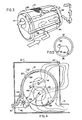
- FIG. 1 A housing 10 is shown which encloses the filtration components of the invention. As is shown in Figure 2, two of the opposing sides of the housing 10 are provided with annular openings 11 and 12. A fluid inlet 14 is also provided for admitting air into the housing 10. Air may be suitably conveyed to the fluid inlet 14 by means of conventional ductwork 15, as is shown in Figures 1 and 2. A fluid outlet 16 is also shown in Figures 1 and 2 for exhausting filtered air from the housing 10 in a manner which will be explained in further detail below. Positioned within the housing 10 is a cylindrical drum 20.
- Drum 20 is mounted for rotational movement within housing 10 by means of roller assemblies 23 and 24 positioned on each opposing end of drum 20.
- the roller assemblies 23 and 24 on one side of housing 10 are shown in Figure 2.
- the other side of drum 20 is mounted in an identical manner.
- Drum 20 is driven by means of a roller chain 25 fixedly secured to one circumferential edge thereof. Chain 25 is matingly engaged by.a sprocket gear 26 which is driven conventionally by an electric motor.
- Drum 20 is formed of expanded metal welded to a cylindrical skeleton. Of course, the amount of support given drum 20 by its underlying skeleton is dependent primarily on the weight it must support without distortion of its cylindrical configuration. Over the expanded metal surface of drum 20 is placed a closely fitting nylon or stainless steel mesh 21 which is intended primarily to filter the larger particles of dust from the air moving therethrough. The surface of drum 20 and the overlying mesh fabric 21 thus define a filter support (broad reference numeral 22) for the formation of an overlying porous layer of dust into a mat "M" which serves as the primary filter.
- a filter support broad reference numeral 22
- shroud 30 Positioned within drum 20 is a shroud 30.
- the shroud 30 forms a physical barrier between the downstream sides of the filter making and filtration zones in housing 10, as will be explained in more detail below.
- Shroud 30 is held in stationary position against the rotation of drum 20 by means of a pair of opposing end caps 31 and 32, which comprise large, shallow, cylindrical "pans" which are slightly smaller in their outside diameters than the inside diameter of drum 20.
- End caps 31 are positioned in annular opening 11, as is shown in Figure 2 and are held in stationary position by upright supports 34 and 35.
- the lower edge of shroud 30 is welded, bolted or otherwise suitably secured against movement to the inner surface of end cap 31.
- End cap 32 is positioned in annular opening 12, and maintained against movement by upright supports (not shown).
- the adjacent end of shroud 30 is fixedly secured to end cap 32 and thereby secured against movement.
- Seals 38 and 39 comprising elongate strips of flexible rubber or plastic-like material, are secured to the longitudinally extending, laterally opposing edges of shroud 30, as is shown in Figures 2 and 4, and sealingly engage the inner circumferential surface of drum.20 along its length.
- the area defined within drum 20 which is sealingly enclosed by the shroud 30 defines the downstream side of a filter making zone 36.
- the remainder of the interior of drum 20 which is not enclosed within shroud 30 therefore defines the downstream side of a filtration zone 37 within which the primary filtering operation carried out by this invention takes place.
- the entire filter making zone 36 is defined on the upstream side of cylindrical drum 20 from the filtration zone 37 only by fluid flow; and on the downstream side by the physical barrier of the shroud 30 and seals 38 and 39.
- the areas within the housing 10 defined by the filter making zone 36 and the filtration zone 37, respectively, are indicated in Figure 5.
- a doffing mechanism comprising a doffer roll 40 having a plurality of radially outwardly extending rubber flaps 40a.
- the doffer roll 40 rotates counterclockwise, causing rubber flaps 40a to successively scrape against the outer surface of drum 20, removing the fiber mat "M" from drum 20 and through a waste outlet 41.
- Intercommunication of air between the filter making zone 36 and waste outlet 41 is prevented at the doffer roll 40 by means of a curved shield 42 which projects inwardly from the waste outlet 41 into close, spaced-apart relation to the outer surface of drum 20.
- the radially, outwardly extending rubber flaps 40a on the doffer roll 40 are spaced sufficiently close together that sealing contact between the rubber flaps 40a and the outer surface of drum 20 is maintained at all times.
- Drum 20, doffer roll 40 and steel roller 43 are rotated periodically in response to a pre-determined pressure drop across drum 20 in the filter making zone 36, i.e. between the area enclosed within shroud 30 and the radially contiguous area outside drum 20 but inside housing 10.
- a pressure senser 45 shown in Figure 2, compares the air pressure on either side of drum 20 within the area described above. When the pressure differential exceeds a pre- determined figure, drum 20 and doffer roll 40 are rotated counterclockwise and the steel roller 43 clockwise. The doffer roll 40 strips the fiber mat "M" from a laterally extending segment of drum 20. This bare segment then passes doffer roll 40 and the adjacent seal 39 into the filter making zone 36. Of course, the pressure differential drops rapidly as the bare filter passes into the filter making zone 36. This drop in pressure differential is sensed by pressure senser 45, stopping the rotation of drum 20, doffer roll 40 and steel roll 43.
- the air which is filtered through the filter support in the filter making zone 36 is filtered a second time in the filtration zone through the filter support 22 and the fiber mat "M" resting thereon.
- the air is conveyed from the downstream side of the filter making zone within the shroud 30 to the upstream side of the filtration zone by means of an annular opening 46 in end cap 32.
- the annular opening 46 communicates with a conventional sheet metal duct 48 which conveys the air to a filtration zone inlet 47, as is shown in Figure 1.
- the air from.the downstream side of the filter making zone 36 is conveyed into the upstream side of the filtration zone 37 by means of a fan 50 positioned within duct 48.
- air in the downstream side of the filtration zone is exhausted from the filter through the annular opening 16 by means of another fan 55 enclosed within a duct 56.
- Air leakage between housing 10 and drum 20 on either side thereof is prevented by means of an annular seal 60 which is made of rubber or a pliable plastic material and which engages housing 10 defining the annular opening 11, and the opposing end portions of the drum 20.
- an annular seal 61 made of a rubber or a pliable plastic material which engages the side walls of end caps 31 and 32, respectively, and the interior edge of drum 20.
- Seals 60 and 61 are sufficiently flexible to engage tightly against their respective bearing surfaces, but to permit rotation of drum 20 without fluid leakage. The placing of a small amount of lubricant between seals 60 and 61 and their respective bearing surfaces aids in creating an airtight seal while decreasing the surface friction while drum 20 is rotating.
- a fiber mat Prior to the operation of the apparatus at maximum efficiency, a fiber mat must be allowed to accumulate. It has been determined that a thickness of approximately 3.8 cm. to 5 cm. is sufficient to provide very high quality air filtration when filtering conventional textile fibers and dust.
- the entire portion of the filter support 22 residing within the filtration zone 37 must be completely covered with a mat of accumulated fibers and dust to a pre-determined minimum thickness. This is accomplished by passing lint and dust laden air into the housing 10 through the inlet 14. The drum 20 is not rotated until the desired thickness is achieved. If desired, the air which is being filtered while the fiber mat is being built on the filter support 22 can be recirculated through the filter repeatedly until the minimum fiber mat thickness is achieved.
- All of the air which passes through the filter support 22 in the filter making zone 36 travels axially along the shroud 30 from its point of entry to annular opening 46 and into duct 48 where it is conveyed to the filtration zone inlet 47.
- the air Entering the filtration zone 37 along the length of the cylindrical drum 20, the air passes through the fiber mat "M" residing on the filter support 22. It is at this stage that the high efficiency filtration takes place. Because the fiber mat is of a uniform thickness throughout the surface area of the filter support 22 within the filtration zone 37, filtration is of a uniformly high quality and the fiber mat "M" is maintained at a very even thickness.
- Air passing through the filter support 22 adjacent seal 39 deposits only its largest fiber and dust particles on the screen 21.
- the remaining particles, including most of the very fine dust and fiber particles, are filtered from the air after it has been conveyed into the upstream side of the filtration zone 37 and thence through the fiber mat "M" into the downstream side of the filtration zone 37.
- the percentage of smaller fibers and dust particles which are filtered out of the air increases.
- the fiber mat "M" is allowed to increase in thickness to the point where the maximum filtration efficiency is achieved just inside the filter making zone 36 adjacent the seal 38.
- the fiber mat "M" in the filter making zone 36 directly adjacent the seal 38 possesses the same high rate of filtration capacity as does the fiber mat "M” in the filtration zone 37 immediately adjacent the seal 38.
- the thickness of the fiber mat "M” in the filtration zone 37 guarantees that the larger dust and fiber particles which would have, in any event, been removed had the air first passed through the filter making zone 36, are removed along with the much finer particles.
- air can be "underfed” into the filter, causing it to be recirculated several times. More and smaller dust particles are removed by each pass through the mat "M", but at the cost of reduced capacity and greater energy consumption.
- Rotation of drum 20 which is necessary to successively clean axially extending strips of fiber mat "M" from the filter support 22 can be accomplished in a variety of ways. If the volume and particulate content of the air being filtered is relatively constant, the time required to build a fiber mat to its optimum thickness can be determined empirically. Then, a simple motor speed control can serve to constantly rotate the drum at the desired speed. In areas where variable air flow or particulate content is anticipated, the pressure senser 45, described above, can be utilized.
- the principle on which the filter operates lends itself to a variety of constructions and uses.
- the same principles described above can be applied to filtering apparatus having flat, rotatable filter "discs", endless bands and the like.
- a first fluid flow can be used'to build a filter mat for use in filtering a second fluid flow.
- the apparatus and method according to the present invention can be adapted for filtration of other fluids, such as water.
- modification of the apparatus can be accomplished to permit filtration of other particulates, such as coal dust, plaster or cement dust, among others.
Landscapes
- Chemical & Material Sciences (AREA)
- Chemical Kinetics & Catalysis (AREA)
- Filtering Materials (AREA)
- Filtering Of Dispersed Particles In Gases (AREA)
Priority Applications (1)
| Application Number | Priority Date | Filing Date | Title |
|---|---|---|---|
| AT82300819T ATE13981T1 (de) | 1981-03-09 | 1982-02-17 | Verfahren und vorrichtung zum filtern von teilchen aus einem fluid. |
Applications Claiming Priority (3)
| Application Number | Priority Date | Filing Date | Title |
|---|---|---|---|
| US06/241,826 US4360369A (en) | 1981-03-09 | 1981-03-09 | Apparatus for filtering particulates from a fluid |
| US241826 | 1981-03-09 | ||
| AU87915/82A AU8791582A (en) | 1981-03-09 | 1982-09-01 | Filtering apparatus and method |
Publications (3)
| Publication Number | Publication Date |
|---|---|
| EP0060040A2 true EP0060040A2 (de) | 1982-09-15 |
| EP0060040A3 EP0060040A3 (en) | 1982-12-29 |
| EP0060040B1 EP0060040B1 (de) | 1985-06-26 |
Family
ID=34275185
Family Applications (1)
| Application Number | Title | Priority Date | Filing Date |
|---|---|---|---|
| EP82300819A Expired EP0060040B1 (de) | 1981-03-09 | 1982-02-17 | Verfahren und Vorrichtung zum Filtern von Teilchen aus einem Fluid |
Country Status (7)
| Country | Link |
|---|---|
| US (1) | US4360369A (de) |
| EP (1) | EP0060040B1 (de) |
| JP (1) | JPS57159518A (de) |
| AU (1) | AU8791582A (de) |
| CA (1) | CA1161768A (de) |
| DE (1) | DE3264358D1 (de) |
| GB (1) | GB2094175B (de) |
Cited By (1)
| Publication number | Priority date | Publication date | Assignee | Title |
|---|---|---|---|---|
| CN103124049A (zh) * | 2011-11-19 | 2013-05-29 | 欧瑞康纺织有限及两合公司 | 用于纺织机械的开关柜 |
Families Citing this family (15)
| Publication number | Priority date | Publication date | Assignee | Title |
|---|---|---|---|---|
| US4427422A (en) | 1981-03-09 | 1984-01-24 | Terrell Machine Company | Method for filtering particulates from a fluid |
| US4470913A (en) * | 1981-09-10 | 1984-09-11 | Terrell Machine Company | Method and apparatus for fluid assisted filter doffing |
| EP0077461B1 (de) * | 1981-10-21 | 1988-04-20 | Maschinenfabrik Rieter Ag | Vorrichtung zum Abtragen einer Vliesschicht an einer drehbaren Filtertrommel |
| FR2524826A1 (fr) * | 1982-04-08 | 1983-10-14 | Beaudrey & Cie | Dispositif de lavage de tamis rotatifs pour prises d'eau d'installations industrielles |
| US4461633A (en) * | 1982-09-28 | 1984-07-24 | Continental Conveyor & Equipment Co., Inc. | Air filtering machinery with variable speed cleaning |
| US4681604A (en) * | 1986-04-29 | 1987-07-21 | Niederer Kurt W | Multistage fluid filter and method |
| US5045601A (en) * | 1989-06-13 | 1991-09-03 | Biointerface Technologies, Inc. | Pressure-sensitive adhesive compositions suitable for medical uses |
| US5453117A (en) * | 1994-03-22 | 1995-09-26 | Luwa Ag | Fluid filter and method of separating entrained particulate matter from a moving fluid stream |
| US7322785B2 (en) * | 2001-05-31 | 2008-01-29 | Air Cure, Inc. | Car dumper dust collection method and apparatus |
| US6960054B2 (en) * | 2001-05-31 | 2005-11-01 | Air Cure, Inc. | Car dumper dust collection method and apparatus |
| US7264422B2 (en) * | 2004-03-25 | 2007-09-04 | Owens-Corning Fiberglas Technology Inc. | Rotary separator for mineral fibers |
| WO2006045138A2 (en) * | 2004-10-29 | 2006-05-04 | Johnson Leslie Vincent P | Dust extractor |
| US7959398B2 (en) | 2008-12-11 | 2011-06-14 | Air-Cure Incorporated | Car dumper dust control system |
| CN113577885B (zh) * | 2021-08-02 | 2022-06-21 | 南京艾宇琦膜科技有限公司 | 一种植物蛋白酶过滤漂洗装置及其实施方法 |
| JP7696636B2 (ja) * | 2023-05-04 | 2025-06-23 | 徳晃有限公司 | 排出ガス浄化装置 |
Family Cites Families (15)
| Publication number | Priority date | Publication date | Assignee | Title |
|---|---|---|---|---|
| US3183647A (en) * | 1965-05-18 | Lang cleaning filter surfaces | ||
| US2023036A (en) * | 1934-09-07 | 1935-12-03 | Southland Cotton Oil Company | Lint collecting apparatus |
| GB912149A (en) | 1960-05-14 | 1962-12-05 | Stockdale Engineering Ltd | Improvements in devices for continuous rotary filtration and extraction |
| US3212239A (en) * | 1961-04-27 | 1965-10-19 | Maestrelli Gino | Apparatus for filtering air or gaseous mixtures |
| DE1510590C3 (de) * | 1963-11-16 | 1975-03-06 | Schubert & Salzer Maschinenfabrik Ag, 8070 Ingolstadt | Vorrichtung zum Reinigen eines Filterstebes |
| US3343342A (en) * | 1964-05-11 | 1967-09-26 | Rocher Lionel J Du | Filter assembly |
| CH419058A (de) * | 1965-01-18 | 1966-08-31 | G A Messen Jaschin Fa | Elektrostatischer Staubabscheider |
| US3525198A (en) * | 1968-05-31 | 1970-08-25 | Murray Co Inc | Fly lint recovery apparatus |
| GB1249159A (en) * | 1968-06-04 | 1971-10-06 | Parks Cramer | Improvements in filters |
| SE330318B (de) * | 1968-09-20 | 1970-11-09 | Svenska Flaektfabriken Ab | |
| US3789587A (en) * | 1971-05-10 | 1974-02-05 | Loew S Theaters Inc | Apparatus for separating material from a pneumatic conveyor |
| CH568780A5 (en) | 1973-05-11 | 1975-11-14 | Luwa Ag | Air filter esp. for removing textile fibres - using a filter drum which is intermittently rotated to remove coating |
| CH599995A5 (de) * | 1975-08-25 | 1978-06-15 | Luwa Ag | |
| CH591054A5 (de) * | 1975-09-23 | 1977-08-31 | Luwa Ag | |
| US4226715A (en) * | 1979-09-24 | 1980-10-07 | The Terrell Machine Company | Apparatus and method for separating entrained particulate matter from a conveying fluid |
-
1981
- 1981-03-09 US US06/241,826 patent/US4360369A/en not_active Expired - Fee Related
-
1982
- 1982-02-17 CA CA000396433A patent/CA1161768A/en not_active Expired
- 1982-02-17 GB GB8204683A patent/GB2094175B/en not_active Expired
- 1982-02-17 DE DE8282300819T patent/DE3264358D1/de not_active Expired
- 1982-02-17 EP EP82300819A patent/EP0060040B1/de not_active Expired
- 1982-03-01 JP JP57030671A patent/JPS57159518A/ja active Pending
- 1982-09-01 AU AU87915/82A patent/AU8791582A/en not_active Abandoned
Cited By (2)
| Publication number | Priority date | Publication date | Assignee | Title |
|---|---|---|---|---|
| CN103124049A (zh) * | 2011-11-19 | 2013-05-29 | 欧瑞康纺织有限及两合公司 | 用于纺织机械的开关柜 |
| CN103124049B (zh) * | 2011-11-19 | 2016-12-21 | 索若德国两合股份有限公司 | 用于纺织机械的开关柜 |
Also Published As
| Publication number | Publication date |
|---|---|
| AU8791582A (en) | 1984-03-08 |
| US4360369A (en) | 1982-11-23 |
| EP0060040A3 (en) | 1982-12-29 |
| JPS57159518A (en) | 1982-10-01 |
| DE3264358D1 (en) | 1985-08-01 |
| GB2094175A (en) | 1982-09-15 |
| GB2094175B (en) | 1984-08-22 |
| EP0060040B1 (de) | 1985-06-26 |
| CA1161768A (en) | 1984-02-07 |
Similar Documents
| Publication | Publication Date | Title |
|---|---|---|
| US4360369A (en) | Apparatus for filtering particulates from a fluid | |
| EP0026069B1 (de) | Vorrichtung und Verfahren zur Abscheidung feinzerteilter Materialien aus einem flüssigen Medium | |
| US5560835A (en) | Pleated belt filter with suction means to remove debris | |
| EP0946248B1 (de) | Filter mit gegenstromreinigung | |
| US4427422A (en) | Method for filtering particulates from a fluid | |
| EP1129757B1 (de) | Gerät zur Mikrofiltration von in einem Flüssigkeitsstrom suspendierten Feststoffpartikeln | |
| US5906752A (en) | Self-cleaning belt filter with edge sealing means and method | |
| US3377780A (en) | Self-cleaning filter apparatus | |
| MXPA97005782A (en) | Self cleaning and met band filter | |
| US4364755A (en) | Filter assembly | |
| US4450080A (en) | Apparatus for removing excess liquid and contaminants from belt filter cake | |
| EP0075403B1 (de) | Verfahren und Vorrichtung zur Entfernung einer Filterschicht unter Mitwirkung einer Strömung | |
| US5584913A (en) | Dust collector with two stage self-cleaning of filter elements | |
| US4710207A (en) | Air filtering apparatus with roller assembly for cleaning | |
| US4470913A (en) | Method and apparatus for fluid assisted filter doffing | |
| US2833417A (en) | Fluid filter apparatus | |
| WO2002020124A1 (en) | Filter | |
| EP0471768B1 (de) | Kontinuierlich arbeitende filterzentrifuge | |
| US4325717A (en) | Seal protector for air filtering apparatus | |
| CA2313871C (en) | Self-cleaning belt filter and method | |
| SU959806A1 (ru) | Фильтр дл сухой очистки газов | |
| EP0821991A2 (de) | Dichtungsapparat und Methode zur Verwendung in einem Bandfilter | |
| AU719839B2 (en) | Filter with counter flow clearing | |
| CA1150158A (en) | Filter for removing fines |
Legal Events
| Date | Code | Title | Description |
|---|---|---|---|
| PUAI | Public reference made under article 153(3) epc to a published international application that has entered the european phase |
Free format text: ORIGINAL CODE: 0009012 |
|
| AK | Designated contracting states |
Designated state(s): AT BE DE FR IT SE |
|
| PUAL | Search report despatched |
Free format text: ORIGINAL CODE: 0009013 |
|
| AK | Designated contracting states |
Designated state(s): AT BE DE FR IT SE |
|
| 17P | Request for examination filed |
Effective date: 19830531 |
|
| GRAA | (expected) grant |
Free format text: ORIGINAL CODE: 0009210 |
|
| AK | Designated contracting states |
Designated state(s): AT BE DE FR IT SE |
|
| PG25 | Lapsed in a contracting state [announced via postgrant information from national office to epo] |
Ref country code: SE Effective date: 19850626 Ref country code: IT Free format text: LAPSE BECAUSE OF FAILURE TO SUBMIT A TRANSLATION OF THE DESCRIPTION OR TO PAY THE FEE WITHIN THE PRESCRIBED TIME-LIMIT;WARNING: LAPSES OF ITALIAN PATENTS WITH EFFECTIVE DATE BEFORE 2007 MAY HAVE OCCURRED AT ANY TIME BEFORE 2007. THE CORRECT EFFECTIVE DATE MAY BE DIFFERENT FROM THE ONE RECORDED. Effective date: 19850626 Ref country code: FR Free format text: THE PATENT HAS BEEN ANNULLED BY A DECISION OF A NATIONAL AUTHORITY Effective date: 19850626 Ref country code: BE Effective date: 19850626 Ref country code: AT Effective date: 19850626 |
|
| REF | Corresponds to: |
Ref document number: 13981 Country of ref document: AT Date of ref document: 19850715 Kind code of ref document: T |
|
| REF | Corresponds to: |
Ref document number: 3264358 Country of ref document: DE Date of ref document: 19850801 |
|
| EN | Fr: translation not filed | ||
| PLBE | No opposition filed within time limit |
Free format text: ORIGINAL CODE: 0009261 |
|
| STAA | Information on the status of an ep patent application or granted ep patent |
Free format text: STATUS: NO OPPOSITION FILED WITHIN TIME LIMIT |
|
| 26N | No opposition filed | ||
| PG25 | Lapsed in a contracting state [announced via postgrant information from national office to epo] |
Ref country code: DE Effective date: 19881101 |