EP0060065A1 - Schalter für tragbare elektrische Werkzeuge - Google Patents
Schalter für tragbare elektrische Werkzeuge Download PDFInfo
- Publication number
- EP0060065A1 EP0060065A1 EP82301021A EP82301021A EP0060065A1 EP 0060065 A1 EP0060065 A1 EP 0060065A1 EP 82301021 A EP82301021 A EP 82301021A EP 82301021 A EP82301021 A EP 82301021A EP 0060065 A1 EP0060065 A1 EP 0060065A1
- Authority
- EP
- European Patent Office
- Prior art keywords
- switch
- housing
- portable electric
- motor
- receptable
- Prior art date
- Legal status (The legal status is an assumption and is not a legal conclusion. Google has not performed a legal analysis and makes no representation as to the accuracy of the status listed.)
- Granted
Links
Images

Classifications
-
- H—ELECTRICITY
- H01—ELECTRIC ELEMENTS
- H01H—ELECTRIC SWITCHES; RELAYS; SELECTORS; EMERGENCY PROTECTIVE DEVICES
- H01H9/00—Details of switching devices, not covered by groups H01H1/00 - H01H7/00
- H01H9/02—Bases, casings, or covers
- H01H9/06—Casing of switch constituted by a handle serving a purpose other than the actuation of the switch, e.g. by the handle of a vacuum cleaner
-
- H—ELECTRICITY
- H01—ELECTRIC ELEMENTS
- H01H—ELECTRIC SWITCHES; RELAYS; SELECTORS; EMERGENCY PROTECTIVE DEVICES
- H01H1/00—Contacts
- H01H1/58—Electric connections to or between contacts; Terminals
- H01H1/5866—Electric connections to or between contacts; Terminals characterised by the use of a plug and socket connector
Definitions
- This invention relates to portable electric tools, such as drills, sanders, honing devices, etc., and improved switch arrangements therein.
- Portable electric tools are usually operated by a trigger-actuated switch mounted in the handle of the tool.
- a feature of the invention by which this is achieved is the provision of plug prongs on the switch itself for receiving directly the female connector of a cord set. This has the advantage of eliminating wiring connections to the switch for the supply cable.
- a portable electric tool having a housing, an electric motor energized by a trigger-actuated switch, and a receptable recessed in the housing containing plug prongs for receiving the female connector of a power supply cable, wherein the plug prongs are formed as terminals of the switch and extend outwardly directly therefrom.
- Fig. 1 shows a trigger-actuated switch, indicated generally by the reference numeral 10, containing a contact-breaking mechanism (not shown) actuated by a manually operable trigger 11 through a mechanical connection shown schematically by a broken line 7.
- the contact-breaking mechanism and the actuation thereof by the trigger 11 are well known to those skilled in the portable electric tool art and will not be further described.
- the switch housing 12 and the trigger 11 are mounted on a supporting structure 8 in known manner having a lug 9 (shown is section) at the lower forward end for attaching the switch 10 to a portable tool.
- a pair of plug prongs 13 (only one of which can be seen in Fig.
- Fig. 2 clearly shows the pair of power supply connection prongs 13 extending rearwardly and the pair of motor connection prongs 14 extending forwardly from the switch housing 12.
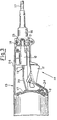
- Fig. 3 shows part of the housing 15 of a portable sander containing an electric motor 22, and having a rearwardly extending handle 24.
- the rear end of the handle 24 has a receptable 18 recessed therein and separated from the interior of the handle 24 by a partition 25.
- the switch 10 is mounted in the handle 24 with a.screw 26 attaching the lug 9 to the rear end of the motor 22.
- An internal motor cable 20, containing the motor leads extends rearwardly from the motor 22 and terminates in a female connector 19 which is slidably engaged on the forward terminal prongs 14 of the switch housing 12.'
- the rear terminal prongs 13 extend outwardly from the switch housing 12, through the partition 25 into the receptable 18.
- a female connector 16 of an external power supply cable 17 is inserted in the receptable 18 with the flat prongs 13 engaging completely in corresponding slots 23 in the connector 16.
- the sander In use, after the power supply cable connector 16 has been inserted in the receptable 18, the sander is operated by manually squeezing the trigger 11 to close the contacts in the switch housing 12 and so energize the motor 22.
- the direct coupling between the connector 16 and the switch 10 contributes to simpler and faster connection of the power supply cable 17. Moreover, such a coupling is highly reliable against short-circuit hazards.
- the switch 10 is simply secured to the motor 22 by the screw 26, the motor cable connector 19 inserted on the prongs 14, and then the complete motor and switch unit placed in a clamshell half of the tool housing 15, no further electrical connections being necessary. It will be appreciated that this simplifies assembly of the tool so reducing production time and cost.
Landscapes
- Details Of Connecting Devices For Male And Female Coupling (AREA)
- Push-Button Switches (AREA)
- Portable Power Tools In General (AREA)
- Driving Mechanisms And Operating Circuits Of Arc-Extinguishing High-Tension Switches (AREA)
- Scissors And Nippers (AREA)
- Switch Cases, Indication, And Locking (AREA)
Priority Applications (1)
| Application Number | Priority Date | Filing Date | Title |
|---|---|---|---|
| AT82301021T ATE13607T1 (de) | 1981-03-04 | 1982-03-01 | Schalter fuer tragbare elektrische werkzeuge. |
Applications Claiming Priority (2)
| Application Number | Priority Date | Filing Date | Title |
|---|---|---|---|
| ITMI1981U20969U IT8120969U1 (it) | 1981-03-04 | 1981-03-04 | Interruttore perfezionato per utensili elettrici |
| IT2096981U | 1981-03-04 |
Publications (2)
| Publication Number | Publication Date |
|---|---|
| EP0060065A1 true EP0060065A1 (de) | 1982-09-15 |
| EP0060065B1 EP0060065B1 (de) | 1985-05-29 |
Family
ID=11174763
Family Applications (1)
| Application Number | Title | Priority Date | Filing Date |
|---|---|---|---|
| EP82301021A Expired EP0060065B1 (de) | 1981-03-04 | 1982-03-01 | Schalter für tragbare elektrische Werkzeuge |
Country Status (5)
| Country | Link |
|---|---|
| US (1) | US4442366A (de) |
| EP (1) | EP0060065B1 (de) |
| AT (1) | ATE13607T1 (de) |
| DE (1) | DE3263842D1 (de) |
| IT (1) | IT8120969U1 (de) |
Cited By (1)
| Publication number | Priority date | Publication date | Assignee | Title |
|---|---|---|---|---|
| GB2223364A (en) * | 1988-07-28 | 1990-04-04 | Bosch Gmbh Robert | Switch-actuated blocking means for connector in power hand tool |
Families Citing this family (7)
| Publication number | Priority date | Publication date | Assignee | Title |
|---|---|---|---|---|
| DE3239238A1 (de) * | 1982-10-21 | 1984-04-26 | Black & Decker, Inc. (Eine Gesellschaft N.D.Ges.D. Staates Delaware), Newark, Del. | Verfahren zum verdrahten von elektrogeraeten, insbesondere elektrowerkzeugen sowie eletrogeraet |
| US4549105A (en) * | 1983-01-07 | 1985-10-22 | Mitsubishi Denki Kabushiki Kaisha | Submergible motor including circuit element encased in molded plug |
| US4491752A (en) * | 1983-03-31 | 1985-01-01 | Black & Decker Inc. | Electrical connection system for switches |
| US5008574A (en) * | 1990-04-04 | 1991-04-16 | The Chamberlain Group | Direct current motor assembly with rectifier module |
| JP3830799B2 (ja) * | 2001-10-17 | 2006-10-11 | 株式会社マキタ | 電動工具と電動工具のための電源接続装置 |
| US7175456B2 (en) * | 2005-02-28 | 2007-02-13 | Robert Bosch Gmbh | Anti-disengagement connect system for a power tool |
| US8179004B2 (en) * | 2009-11-06 | 2012-05-15 | Shop Vac Corporation | Motor assembly with switch module |
Citations (4)
| Publication number | Priority date | Publication date | Assignee | Title |
|---|---|---|---|---|
| GB679874A (en) * | 1950-03-09 | 1952-09-24 | Horstman Ltd | Improvements in or relating to electric switches suitable for use in hand-operated portable electrical apparatus |
| US2955183A (en) * | 1958-09-29 | 1960-10-04 | Hoover Co | Electric current conducting hose and switch |
| GB1119110A (en) * | 1965-11-26 | 1968-07-10 | Gen Electric | Improvements in switch and terminal assembly for selectively controlling dynamoelectric machine winding circuits and the like |
| US3843224A (en) * | 1972-12-21 | 1974-10-22 | Black & Decker Mfg Co | Detachable cord set for electric device |
Family Cites Families (5)
| Publication number | Priority date | Publication date | Assignee | Title |
|---|---|---|---|---|
| US2513271A (en) * | 1948-06-30 | 1950-07-04 | Cummins Business Machines Corp | Housing for portable motor driven tools |
| US2860201A (en) * | 1954-12-02 | 1958-11-11 | Ceman Conord | Arrangements of electrical connections in a vacuum cleaner |
| US2975391A (en) * | 1957-02-19 | 1961-03-14 | Electrolux Corp | Combined handle and electric plug retainer |
| US3054994A (en) * | 1958-07-30 | 1962-09-18 | Haram Arthur Carsten | Visual signal generation and electrical outlet control means therefor |
| US4104606A (en) * | 1976-12-23 | 1978-08-01 | Lutron Electronics Co., Inc. | Dimmer switch with insulation housing |
-
1981
- 1981-03-04 IT ITMI1981U20969U patent/IT8120969U1/it unknown
-
1982
- 1982-03-01 AT AT82301021T patent/ATE13607T1/de active
- 1982-03-01 EP EP82301021A patent/EP0060065B1/de not_active Expired
- 1982-03-01 DE DE8282301021T patent/DE3263842D1/de not_active Expired
- 1982-03-02 US US06/353,918 patent/US4442366A/en not_active Expired - Fee Related
Patent Citations (4)
| Publication number | Priority date | Publication date | Assignee | Title |
|---|---|---|---|---|
| GB679874A (en) * | 1950-03-09 | 1952-09-24 | Horstman Ltd | Improvements in or relating to electric switches suitable for use in hand-operated portable electrical apparatus |
| US2955183A (en) * | 1958-09-29 | 1960-10-04 | Hoover Co | Electric current conducting hose and switch |
| GB1119110A (en) * | 1965-11-26 | 1968-07-10 | Gen Electric | Improvements in switch and terminal assembly for selectively controlling dynamoelectric machine winding circuits and the like |
| US3843224A (en) * | 1972-12-21 | 1974-10-22 | Black & Decker Mfg Co | Detachable cord set for electric device |
Cited By (2)
| Publication number | Priority date | Publication date | Assignee | Title |
|---|---|---|---|---|
| GB2223364A (en) * | 1988-07-28 | 1990-04-04 | Bosch Gmbh Robert | Switch-actuated blocking means for connector in power hand tool |
| GB2223364B (en) * | 1988-07-28 | 1992-07-22 | Bosch Gmbh Robert | Power hand tools |
Also Published As
| Publication number | Publication date |
|---|---|
| ATE13607T1 (de) | 1985-06-15 |
| EP0060065B1 (de) | 1985-05-29 |
| DE3263842D1 (en) | 1985-07-04 |
| IT8120969V0 (it) | 1981-03-04 |
| IT8120969U1 (it) | 1982-09-04 |
| US4442366A (en) | 1984-04-10 |
Similar Documents
| Publication | Publication Date | Title |
|---|---|---|
| CN109980399B (zh) | 一种智能化仪器仪表数据总线连接器 | |
| US5766020A (en) | Power adapter interface apparatus | |
| EP1999540B1 (de) | Isolierter doppelter wechselstrom-gleichstrom-stecker | |
| US6774603B2 (en) | Multi-function charger | |
| EP0071356A2 (de) | Schnurlose elektrische Vorrichtung mit verbesserten Kontakten | |
| US6280229B1 (en) | Plug connector | |
| GB2089587A (en) | Duplex electrical receptacles | |
| US4201431A (en) | Universal adaptable three-prong electrical plug | |
| EP0025938B1 (de) | Druckschalter und gedruckte Schaltungsanordnung für ein tragbares Werkzeug | |
| KR102010288B1 (ko) | 전기자동차용 충전장치 | |
| EP0060065B1 (de) | Schalter für tragbare elektrische Werkzeuge | |
| ES2000445A6 (es) | Disposicion de conexion auto-desnudante encastrada para instalacion electrica y util de conexion para dicha disposicion | |
| US5833357A (en) | Trouble light | |
| US4939843A (en) | Portable handheld circular saw | |
| CN101647160B (zh) | 加长电缆和与其配合的管加工装置 | |
| CN210201002U (zh) | 一种母线插接箱的弹性插脚结构 | |
| US3985412A (en) | Grounding electrical adapter | |
| WO1986000762A1 (en) | Battery-switch module adapter | |
| JPS5857875B2 (ja) | ケ−ブル取外し工具 | |
| US3057975A (en) | Plug connector with switch for auxiliary starting circuit | |
| CN211655230U (zh) | 一种用于电源逆变器的交流插座 | |
| US5615103A (en) | AC-DC adaptor/battery eliminator | |
| NL2023687B1 (en) | Assembly of a housing, an electronic or electric component and a preferably quick-connect cable adapter/connector | |
| GB2144929A (en) | Multi-pin electrical connector | |
| KR200260354Y1 (ko) | 전동공구용 트리거 스위치 |
Legal Events
| Date | Code | Title | Description |
|---|---|---|---|
| PUAI | Public reference made under article 153(3) epc to a published international application that has entered the european phase |
Free format text: ORIGINAL CODE: 0009012 |
|
| AK | Designated contracting states |
Designated state(s): AT BE CH DE FR GB IT LU NL SE |
|
| 17P | Request for examination filed |
Effective date: 19820916 |
|
| ITF | It: translation for a ep patent filed | ||
| GRAA | (expected) grant |
Free format text: ORIGINAL CODE: 0009210 |
|
| AK | Designated contracting states |
Designated state(s): AT BE CH DE FR GB IT LI LU NL SE |
|
| PG25 | Lapsed in a contracting state [announced via postgrant information from national office to epo] |
Ref country code: NL Effective date: 19850529 Ref country code: LI Effective date: 19850529 Ref country code: CH Effective date: 19850529 Ref country code: BE Effective date: 19850529 Ref country code: AT Effective date: 19850529 |
|
| REF | Corresponds to: |
Ref document number: 13607 Country of ref document: AT Date of ref document: 19850615 Kind code of ref document: T |
|
| PG25 | Lapsed in a contracting state [announced via postgrant information from national office to epo] |
Ref country code: SE Effective date: 19850530 |
|
| REF | Corresponds to: |
Ref document number: 3263842 Country of ref document: DE Date of ref document: 19850704 |
|
| ET | Fr: translation filed | ||
| REG | Reference to a national code |
Ref country code: CH Ref legal event code: PL |
|
| NLV1 | Nl: lapsed or annulled due to failure to fulfill the requirements of art. 29p and 29m of the patents act | ||
| PG25 | Lapsed in a contracting state [announced via postgrant information from national office to epo] |
Ref country code: LU Free format text: LAPSE BECAUSE OF NON-PAYMENT OF DUE FEES Effective date: 19860331 |
|
| PLBE | No opposition filed within time limit |
Free format text: ORIGINAL CODE: 0009261 |
|
| STAA | Information on the status of an ep patent application or granted ep patent |
Free format text: STATUS: NO OPPOSITION FILED WITHIN TIME LIMIT |
|
| 26N | No opposition filed | ||
| ITTA | It: last paid annual fee | ||
| PGFP | Annual fee paid to national office [announced via postgrant information from national office to epo] |
Ref country code: GB Payment date: 19950217 Year of fee payment: 14 |
|
| PGFP | Annual fee paid to national office [announced via postgrant information from national office to epo] |
Ref country code: FR Payment date: 19960221 Year of fee payment: 15 |
|
| PGFP | Annual fee paid to national office [announced via postgrant information from national office to epo] |
Ref country code: DE Payment date: 19960223 Year of fee payment: 15 |
|
| PG25 | Lapsed in a contracting state [announced via postgrant information from national office to epo] |
Ref country code: GB Effective date: 19960301 |
|
| GBPC | Gb: european patent ceased through non-payment of renewal fee |
Effective date: 19960301 |
|
| PG25 | Lapsed in a contracting state [announced via postgrant information from national office to epo] |
Ref country code: FR Free format text: LAPSE BECAUSE OF NON-PAYMENT OF DUE FEES Effective date: 19971128 |
|
| PG25 | Lapsed in a contracting state [announced via postgrant information from national office to epo] |
Ref country code: DE Effective date: 19971202 |
|
| REG | Reference to a national code |
Ref country code: FR Ref legal event code: ST |